1
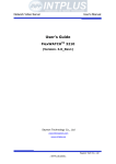
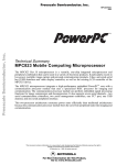
Technical
Manual
This manual is a supplement to the Spectra Installation
Guide. Please refer to the Installation Guide for
Installation Instructions.
Trademarks & Copyrights
Copyright ©1999 by Evergreen Technologies, Inc. All rights reserved.
Brand and product names are trademarks or registered trademarks of their respective holders.
Printed in the USA.
CONTENTS
Overview..................................................................................................1
Hardware and Software............................................................................1
System Requirements...............................................................................1
How the Upgrade Works..........................................................................1
How to Use This Manual .........................................................................2
Conventions used in this manual:.............................................................2
TECHNICAL INFORMATION
3
Product Technology .................................................................................4
TECHNICAL SUPPORT
5
Solving Problems Yourself
6
Problem/Solution Index ...........................................................................6
Installation Issues
7
Fitting CPU into Socket ...........................................................................7
What to do with your old Fan ..................................................................7
Bent processor pins ..................................................................................7
No power or sound ...................................................................................7
System Issues
8
Computer starts to boot, but the screen is blank ......................................8
Configuring Your Ports – Printer / Modem are missing ........................10
CD-ROM not recognized or not functioning .........................................10
DOS Compatibility Mode ......................................................................10
System hangs while running Applications
12
Stability issues while booting/running under Windows .........................13
Performance Issues
15
Benchmarks do not give correct reading of upgrade speed....................15
Computer does not run fast enough with upgrade .................................15
Solving CMOS Problems.......................................................................17
APPENDIX
19
Getting Help
20
Before Contacting Evergreen.................................................................20
How to Contact Evergreen .....................................................................20
Technical Support Questionnaire ...........................................................21
Glossary
22
Install Flowchart
24
Overview
Thank you for purchasing the Evergreen Spectra™ upgrade processor upgrade. We created
this overview to explain the central ideas behind upgrading your computer.
If you are inexperienced at installing computer hardware, you may want to have an
experienced friend or qualified computer technician install the upgrade for you.
Hardware and Software
The upgrade hardware is a processor upgrade module with cooling fan. The upgrade
hardware replaces your computer’s pre-existing processor. It fits into the existing processor
socket on your computer’s motherboard.
The upgrade software is called INSTALL. This software examines your system for upgrade
support. If INSTALL determines that Evergreen Technologies has a BIOS upgrade for
your system, you will need to follow the instructions on both the CD and the Installation
Guide. INSTALL also runs a performance test before and after installing the upgrade to
help you verify the performance improvement and run diagnostics.
System Requirements
The Evergreen upgrade can replace all single Intel® Pentium® processor class CPUs with
speed ratings of 75 MHz and above in qualified motherboards. The upgrade cannot
currently replace 60, 66 MHz or Pentium processor class CPUs in many dual processor
systems.
How the Upgrade Works
The upgrade is a powerful next generation AMD® K6-2™ processor. It replaces your slower
Pentium processor level CPU and delivers performance comparable to that of today’s
processors.
Make sure you have the right upgrade for your computer. The upgrade is designed to
upgrade 75 MHz and higher CPUs. This includes processors from Intel, AMD, Cyrix® and
IDT®.
Evergreen Upgrade Technical Manual
1
How to Use This Manual
This manual is divided into two chapters:
Chapter
Purpose
Do you need this chapter?
Technical
Information
Provides Technical Information
about the product.
Use this chapter to look up
technical information on the
upgrade.
Technical
Support
Explains how to troubleshoot
problems related to installing the
upgrade. Tells how to contact
Evergreen. Explains new terms
related to upgrading.
Use this chapter if you have
problems, are confused by the new
terms, or need to contact
Evergreen.
2
Overview
Technical
Information
Evergreen Upgrade Technical Manual
3
Product Technology
This product is based on an AMD K6®-2 processor with 3DNow!™ technology.
4
AMD-K6-2 Pentium
w/ 3DNow! 75 MHz
Processor Features
Performance Benefits
Process Technology
(in microns)
Smaller process = faster performance
00.25
00.35
L1 cache
Built-in feature that helps the CPU
retrieve even faster
64Kb
32Kb
L2 cache support
Augments L1 cache, making data
retrieval even faster
Yes
No
MMX™ technology
Enhances multimedia applications and
runs other apps 10% faster
Yes
No
3DNow! technology
Enables superior visual and multimedia
experience
Yes
No
x86 compatibility
Standard industry architecture, essential
for running standard PC applications
Yes
Yes
Technical Information
Technical Support
Evergreen Upgrade Technical Manual
5
Solving Problems Yourself
Problem/Solution Index
Problem
Solution
Page
INSTALLATION ISSUES
Fitting CPU into socket
Old and new fan
Bent CPU pins
No power from system
Getting the correct fit
What to do with your old fan
What to do with bent pins
No power or sound
7
7
7
7
SYSTEM ISSUES
Blank screen
My CD ROM is not recognized
My printer or modem is missing
System hangs OS/applications
System hangs Windows® 95/98
My benchmarks do not work
correctly
System not fast enough after
upgrade
Computer starts to boot, but the screen is
blank
Correct CD ROM configuration
Hardware resolution with MR BIOS
System instability
Power management/divide overflow/
Phoenix BIOS
PERFORMANCE ISSUES
Why benchmarks may misidentify your
Evergreen processor upgrade
Need to change jumpers or switches
8
10
10
12
13
15
15
SOLVING CMOS PROBLEMS
Replacing run down CMOS
Hardware difficulties
6
Technical Support
When to replace run down CMOS
Checking hardware
17
17
Installation Issues
Fitting CPU into socket
Check the seating of the processor. There should be no space between the bottom of the
upgrade processor and the top of the CPU socket. A level flush mount is crucial. Install
using both hands. One hand holding the upgrade in position, while closing the ZIF lever
with the other. There may be additional notes in your system manual that you should
follow.
What to do with your old fan
Many times your old fan is wired to the power supply. It would not be wise to remove this
fan from your system, as this may void your system warranty. Try to find an out-of-theway spot inside your case that you can secure this fan. Be sure that the fan is secured so it
does not move around inside the case and cause damage.
Bent processor pins
If you bend one or more pins on the original processor or the upgrade, you need to
carefully bend them back to their correct positions using fine point needle nose pliers or
tweezers. In some instances, you may need to contact Technical Support
No power or sound
If your system does not power up when you turn it on (no lights, fan, or power supply
sound):
1.
Turn off your computer immediately!
2.
Verify pin 1 orientation of both the upgrade and the socket, and check the upgrade for
bent pins.
3.
Verify that all internal and external cables are connected properly.
4.
If your system still does not power up, you may have a short in your system. To find
out, turn your computer off, reinstall your original CPU, and turn on your system.
♦ If it DOES power up as normal, with lights and fan/power supply sound, turn your
system off. Install the upgrade again, making sure that you have correctly aligned
pin 1 on the upgrade and socket.
♦ If it DOES NOT power up as normal, you may have a short in your system. Have
someone knowledgeable about computers review the installation.
Evergreen Upgrade Technical Manual
7
System Issues
Computer starts to boot, but the screen is blank or the system
will not boot
Not all system board BIOS/chipset combinations initialize CPU upgrades correctly. This
can result in no video display after the upgrade has been installed. This loss of display can
also be caused by faulty electrical connections. Below are steps that may resolve such
problems.
Power connections:
Look for any connections that may be loose or disconnected. Correct orientation of power
connectors to drives and other peripheral connected to the power supply is very important.
Power supply, motherboard and monitor should be checked for loose connections. In some
cases the power supply fan does not spin. This is most commonly caused by false or
improper installation of motherboard power.
System connections:
Confirm that data (ribbon) cables to all devices are plugged in correctly. This includes tape
drives, hard drives, CD-ROM drives, DVD drives, Zip drives, etc… Pin one indicator for
data cables and power wires are represented by the color red. There is a color stripe
(usually red) on all ribbon cables to indicate their “pin one” side. This “pin one” on the
drive connections is usually the pin closest to the power connector. Check that all other
cables are oriented correctly with matching “pin ones”, and that they are fully seated.
Correct alignment is critical.
Cards:
Make sure that all of the cards in your system are firmly seated and secured in their slots.
Apply pressure evenly along the entire length of the card to ensure proper seating.
Motherboard settings:
Prior to changing any jumper settings on the motherboard, record the current jumper
settings.
Check to see if your motherboard is set to the Intel P54C (standard Intel Pentium) CPU
type. Alternate processor types may also work with CPU upgrade kits. If your system does
not specify this specific processor, try setting jumpers according to the CPU manufacturer.
(Intel, AMD, Cyrix etc…)
The AT/ISA bus clock setting can also affect the way your upgrade is running. A jumper
on the motherboard may control these options. This setting may be part of the “CPU clock"
jumper configuration. Insure that these settings are all set correctly. The ISA bus clock
setting is especially important for the operation of 8 or 16 bit ISA cards installed on the
8
Technical Support
motherboard. You should target 8.33 MHz for this setting. This is calculated by dividing
the bus speed by the AT/ISA bus clock setting divisor.
Some machines require very specific settings to get them to run properly. These settings
can be obtained through Evergreen Technical Support.
BIOS/CMOS settings:
Your system manual should tell you how to access the CMOS/BIOS setup program.
BIOS
Manufacturer
AMI and Award
Phoenix
Compaq
MR BIOS
IBM
How to enter BIOS settings
During the POST process (memory test), the system displays the prompt
to “press DEL for Setup”. Press the Delete key at this time
Press the F2 key after memory count. Others use a CTRL-ALT- “X”
combination. (“X” = S, ESC or F1 keys)
Memory count, two beeps then press the F10 or F1 key before the OS
(Operating System) loads.
Press <Esc> during the power-on memory test, or, press
<Ctrl+Alt+Esc> during run time.
F1 key when the IBM logo appears. A box may be displayed in the
upper right hand corner during this time.
Note: Whenever making changes to the BIOS, you should first take a moment to record
your current settings. If there is a problem with the upgrade installation, you may need to
reinstall your original processor to allow the BIOS to restore its default settings. Once you
have modified the BIOS, you will need to power down the system and reinstall the upgrade
processor. If these steps do not solve your problem, set the BIOS back to its original
settings. Always limit the number of changes made in the BIOS setup to only two at a time.
This will aid in monitoring system response to each BIOS setting change.
Caution: Whenever installing or removing a processor from the socket, you should be
extremely careful with the CPU pins. The pins are very fragile and can be broken easily.
CMOS settings you may want to try
Note: not all BIOS’s have these settings
Disable the Auto configure function and Memory Re-mapping or Relocation. They are
usually in the Advanced Chipset Menu. In the IBM BIOS disable the Read Pre-fetch
feature.
Disable any Power management features enabled in the BIOS.
Disabling Hidden Refresh, Above one Meg Test, and Parity checking may improve
timing.
Evergreen Upgrade Technical Manual
9
Set read/write wait states (DRAM Read/Write and Cache Read/Write) to the middle or
highest settings available.
Set the Video BIOS shadowing and System BIOS shadowing to disable.
Disable Adapter ROM Shadowing as well. You should also disable any energy saving
features in your system.
Disable PCI bursting. Set the PCI host wait states to mid-range. Disable PCI auto
configuration.
Note: System ROM shadowing and Video ROM shadowing should be among the first
options to be enabled after the upgrade is operational.
CD-ROM not recognized or not functioning
Many computer manufacturers shipped CD-ROMs with an incorrect configuration. If your
CD-ROM seems to have stopped functioning, it is probably due to the master/slave settings
on the CD-ROM drive itself. First change the setting on the CD-ROM to master. Then
check to make sure the CD-ROM is connected to the secondary IDE port and confirm that
all connections are tight.
Resolution of hardware issues with MR BIOS
If you have an add-in Parallel Card, shut the system down and physically remove it (it will
be reinstalled later). If your printer is ‘daisy chained’ to a scanner, unplug the scanner from
the system and plug the printer directly into the parallel port (it will be reinstalled later).
Part 1: If the 333/400 MHz CPU has been installed, place the original CPU back into the
machine but do not restore original BIOS from the Spectra install floppy. The MR BIOS
will support the original CPU. Changes to BIOS settings are as follows:
1. Turn the system power off
2. Open MR BIOS Setup at power on by hitting the Esc key just after the memory count
3. Use the Right/Left Arrow keys to move from menu tab to menu tab
4. Use the Up/Down Arrow keys to access specific settings
5. Use the spacebar or Plus/Minus keys to change a setting
6. After making a change, hit the Esc key to access the menu tabs again
7. When the changes listed below are complete, return to the Summary Screen and hit
F10 to Save and Exit
a. Energy – Press the Down Arrow key to IDE spin down and press the minus key
once. Repeat the process for all items in the energy section except for “Event
Monitoring” and “Factory Test Mode.”
10 Technical Support
b.
c.
d.
Ports – Use the Down Arrow and other arrow keys to select Parallel Port Mode.
Use the spacebar to change Parallel Port Mode to “ECP.” Set “onboard 2” to
“NA.”
Chip Set – Make sure the Memory type is set to “70ns.”
Advanced – Make sure that IRQ 12 is set to “Legacy/ISA.”
Part 2: Windows in Safe Mode
1. For Win 95, watch for the following message after the BIOS screen in the boot
sequence, “Starting Windows 95…” Be ready to press the F8 key IMMEDIATELY.
There will only be 2 seconds to catch the prompt.
For Win 98, after the BIOS screen in the boot sequence, begin holding down the
CTRL key.
(If the Windows logo screen is displayed, the chance to access the Startup Menu has
been missed. Wait for Windows to finish booting, perform a normal Shut Down, and
try again from the beginning of Part 2.)
2. From the Startup Menu, select Safe Mode (usually option 3) and press Enter.
Safe Mode will usually take longer to boot than normal mode, so do not be alarmed if
the system takes an unusually long time to finish loading Windows.
Part 3: Removing outdated drivers from Device Manager
1. Click the Start button.
2. Point to Settings.
3. Click Control Panel.
4. Double-click the System icon.
5. Click the Device Manager tab.
6. Click the plus sign (+) next to “Ports, COM and LPT.”
7. Highlight the first device labeled “Printer Port of LPT.”
8. Click remove.
9. Click ok on the Confirm Device Removal window.
10. Repeat steps 7-9 for all “Printer Port” or “LPT’ devices.
11. Click Close.
12. Click Start, Shut Down and Restart.
Part 4: Allowing Windows to redetect hardware
1. Allow Windows to start normally.
(Do not be alarmed if Windows takes an unusually long time to finish loading during
the first boot after being in Safe Mode.)
2. Click Start.
3. Point to settings.
4. Click Control Panel.
5. Double click Add new Hardware
6. Allow Windows to search for new hardware.
7. Say no if asked whether the hardware being installed is on the list displayed.
8. Allow Windows to search for all non-Plug-and-Play hardware.
9. When the search is complete, click Details, and write a list of what was found.
Evergreen Upgrade Technical Manual
11
10. Let Windows install any needed drivers. The Windows CD may be needed.
11. If Windows asks to restart, say Yes.
12. If Windows does not request a restart, do a standard restart anyway.
Part 5: Reinstalling printer software.
After Windows finishes installing new printer port drivers, it may be necessary to remove
and then reinstall any software needed by the specific printer(s) attached to the computer.
In each case, follow the instructions provided by the printer manufacturer.
If you had removed an add-in parallel card, reinstall it following the directions that it
originally came with. If you had removed a scanner, reinstall it following the directions
that it originally came with.
System hangs while running applications
Describes specific issues for systems that begin to boot up but stop due to error messages
or instability. These settings may vary according to your system and your BIOS version. If
you need definitions of terms used in this section, check your system manual.
Warning: If you are not familiar with the BIOS setup routine, do not change your BIOS
settings without recording the original settings. The BIOS setup routine accesses and alters
the information in the CMOS memory.
Connections:
Check CPU seating. To insure that the chip is fully seated, please install the processor with
both hands:
1. Power off the system.
2. Lift the ZIF lever.
3. Using one hand, apply pressure on two corners of the upgrade’s cooling
device.
4. Lower the ZIF lever to the closed position.
5. Verify that the fan on the upgrade is spinning when the system is powered on.
Possible CMOS settings:
For more information on individual settings please see your system manuals. Your manual
should provide specific information about the settings in your BIOS.
Shadow memory cacheable: Selecting “Yes” for this option may increase system
performance. However, cacheable shadow memory has also been known to cause system
conflicts.
Memory timings: In some BIOS’ you will need to change memory configurations to get the
upgrade to work correctly. This should only need to be done if you have had to change
motherboard settings.
Ram timing: Some BIOS’s allow you to manually configure memory settings. FPM SIMM,
EDO SIMM, and SDRAM/DIMM are the most common memory types. It will be often
12 Technical Support
shown as “X2222”. Raise these settings as high as they will go. e.g. “X3333”. Disable all
“bursting” options.
If the above steps work you may be able to change some of the settings back to their
original values. Do these steps one at a time and record any changes you make so you can
easily restore the original settings if necessary.
Stability problems while loading or running under Windows®95
Possible solution #1: Power Management
The original Advanced Power Management (APM) driver for Windows 95 release 1 (4.00
950 or 4.00 950a) may not function correctly on some machines. The release level for the
OS can be found under System Properties.
Disable any power saving features in the BIOS and Place a ";" (remark) in front of the line
"device=*vpowerd" in the SYSTEM.INI file.
Turn on the computer. Start Windows 95 in safe mode by pressing "F5" when the monitor
displays "Starting Windows 95".
Once Windows 95 has loaded in safe mode, press the Start button and choose "Run".
Type "system.ini" in the dialog box, and press Enter. This will run the System Editor.
Select the Search menu click on "Find", then type "*vpowerd" in the box provided.
This will move your view to the device=*vpowerd line, in the [386enh] section of the
system.ini file
Move the cursor to the beginning of the line and place a ";" (semicolon) in front of the
word "device" so it looks like this: ";device=*vpowerd"
Select the File menu and then click Save.
Restart Windows 95.
Possible Solution #2: Divide Overflow Error
Your system freezes or locks up loading Windows 95 and reports a "Divide Overflow”
error." Programs such as “QEMM” and “EMM386” may mask the “Divide Overflow”
error. These programs may cause conflict with older CD-ROM drivers and halt the system.
It is not always clear what caused the error.
Place REM in front of "DEVICE=C:\[path]\cr_atapi.sys" CD/ROM real mode driver in the
CONFIG.SYS file, which is located in the root directory of the C: drive. This driver is
often located in the \PBTOOLS directory on Packard Bell systems.
Press F8 when the text "Starting Windows 95" appears on the screen. Choose "Safe mode”
command prompt only as the start up method. At the C:\ prompt, type "EDIT
CONFIG.SYS" and press enter.
Find the line "DEVICE=C:\[path]\cr_atapi.sys", and place a ";" or "REM" in front of that
line. Save the file and exit the DOS editor. Re-start the system.
Evergreen Upgrade Technical Manual
13
Note:
If you use the CD-ROM in DOS mode, it may be necessary to install a current
16-bit driver. Please confirm the make of your CD-ROM drive before downloading and
installing the 16 bit driver. It is recommended that you download your 16-bit CD-ROM
driver from the OEM (Original Equipment Manufacturer).
POST mode lockups: Phoenix BIOS
Note: Can occur in specific systems with Phoenix BIOS version 4.XX BIOS.
Disabling the “Summary Screen” in the BIOS setup corrects this problem. The setting is
found under the "Boot Options" in the BIOS setup utility.
14 Technical Support
Performance Issues
Benchmarks do not give correct reading of upgrade speed
Benchmarks allow the user and Technical Support to check processor performance before
and after the Evergreen upgrade is installed. No single benchmark is accurate 100 percent
of the time, especially with upgrade processors. While most benchmark programs are really
quite accurate when testing standard machines, most of these same benchmarks fail to
accurately identify and test the Spectra upgrade processor. Still, many users prefer to use
other benchmarks to test the validity of the Dhrystone and Mediastone benchmark. This
often leads to inaccurate readings that should be ignored. Evergreen has found that the
Dhrystone and Mediastone benchmark does the best job of identifying and testing all of the
various system and processor combinations.
Computer does not run fast enough with upgrade installed —
need to set jumpers’
It may be unnecessary to change your motherboard settings for some Spectra upgrades. The
Installation Guide, INSTALL software and this technical note should provide enough
information on when it is necessary to change your hardware settings. If the installation
software reports that the upgrade is functioning properly and identifies it at the correct
speed grade “MHz.”, your upgrade is running correctly.
The following settings may be available as changeable jumpers and/or switches on the
motherboard. Consult your computer manuals for specific information on your
motherboard settings.
No motherboard manual:
There are several places the settings may be located. Check the inside of the computer case
cover. Check the power supply, or silk screen on the motherboard itself. If you do not have
documentation on your motherboard, contact the system or motherboard manufacturer.
They should be able to provide you with the motherboard settings. These settings are also
found on the OEM web site.
Note: Before making changes take a moment and record your current jumper settings.
CPU type: Most motherboards support multiple CPU types. We recommend that you
configure your system board for a standard Intel Pentium processor. Alternate CPU settings
may work as well. If you are having problems with the Intel Pentium settings try the
documented alternate settings.
Evergreen Upgrade Technical Manual
15
Bus speed: Most CPU’s run at a multiple of the Bus Speed (motherboard speed, or external
clock speed). Common bus speeds are 50, 60, and 66 MHz. Many of these Pentium
motherboards can be reconfigured to run at these different speeds. Set your motherboard to
the recommended speed setting for the upgrade you purchased. These are listed on the
Installation Guide that was included with your upgrade. Consult the user's manual or
motherboard documentation for information on changing the motherboard bus speed if
necessary.
Original CPU Speed
Bus Speed
Pentium – 75
50
Pentium – 90/120/150/180/240
60
Pentium – 100/133/166/200/233
66
CPU multiplier: This setting allows the system to achieve higher processor speeds by
multiplying the bus speed. A 50MHz bus with a multiplier set to 1.5X will run the CPU at
75MHz. The multiplier setting on the motherboard can usually be left in its original state.
The upgrade has been designed so that the multiplier is permanently set and not
configurable by the motherboard.
Voltage: The Spectra AMD K6-2 processor voltage should be configured for the “VRE”
setting (3.52 or 3.45 – 3.6v). Some motherboards do not provide the settings to allow you
to configure the voltage, they are incorporated into the CPU type settings. Occasionally,
voltage settings are documented in the manual, but are physically missing from the
motherboard. This usually means that the voltage is controlled automatically and cannot be
changed.
AT bus speed: Many of the adapter cards in your system run at a divisor of the bus speed.
Set this divisor so that the result is approximately 8.33MHZ. Many systems are capable of
running the AT bus as high as 11 MHz. If your system becomes unstable you should
reduce this setting. See below for recommended settings
Bus Speed (MHz)
Clock Divisor
50
60
66
/6, /3, 8.33MHz.
/8, /4, 7.5MHZ.
/8, /4, 8.33MHz.
16 Technical Support
Solving CMOS Problems
CMOS-based problems include:
♦ hanging
♦ error messages
♦ losing memory
♦ incomplete memory count on boot up
♦ losing date, time, and disk-drive settings
♦ system not recognizing devices
The CMOS is a small, battery-powered memory chip that retains system configuration
information, even when the system is turned off. The BIOS uses the information in the
CMOS memory for configuring the system during start-up.
Replacing run-down CMOS
The battery powering the CMOS memory eventually runs down, and the information stored
in the CMOS memory can be lost or become corrupted. Usually the first indicators of a low
CMOS battery are the date and time slowing or being reset (usually to 1/1/80). To solve
this problem, replace your CMOS battery.
Checking hardware
If your system still does not work, the problem may be hardware related (DIP switches,
cards not inserted properly, etc.). Carefully double-check all connections and settings.
Evergreen Upgrade Technical Manual
17
18 Technical Support
Appendix
Evergreen Upgrade Technical Manual
19
Getting Help
If you have tried the solutions recommended in this manual and are still having problems
getting your computer to work properly, please contact Evergreen Technical Support as
described in this section.
Before contacting Evergreen
1.
Complete the “Information for Technical Support” questionnaire in this section.
2.
Prepare to contact Evergreen using one of the methods below. Have your computer in
front of you with the case open and REPORT.TXT printouts if you are going to
contact Evergreen by telephone.
3. Be ready to provide questionnaire information as requested.
How to Contact Evergreen
Method
Contact information
Notes
Telephone
541-757-7341
Have information as
requested on following
pages ready
Fax
541-752-9851
Provide information as
requested on following
pages
E-mail
[email protected]
Provide information as
requested on following
pages
World
Wide Web
http://www.evertech.com
This site offers a wide range
of technical information
Mail
Evergreen Technologies, Inc.
Attn. Technical Support
806 NW Buchanan Avenue
Corvallis, OR 97330-6218
20 Appendix
Technical Support Questionnaire
Type of information
Example
Where to find
The problem
Worked fine yesterday,
but now hangs when it
tries to boot
n/a
Your upgrade model
Evergreen Spectra
The upgrade box
Where you purchased
upgrade
Joe’s Computers,
San Jose, CA
Receipt from store
PC brand and model
Gateway 2000 P5-75
Computer case
Brand and model of
hardware effected
Creative Labs Sound
Blaster (internal card),
SupraModem 288 VFC
(external peripheral)
Hardware labels or in the
manuals
RAM in your system
8 MB of RAM
Displayed when system boots
System’s CPU speed
75 MHz
INSTALL software
Operating system(s)
Windows 95
Displayed when system boots
BIOS manufacturer,
version number, and
date
AMI 1.00.04.BS0T
Displayed when system boots
Names and version
numbers of software
effected
Norton Utilities, RAM
Doubler
Software disk labels, on
software start-up screens
INSTALL reports
printed before AND
after installation
INSTALL software
Evergreen Upgrade Technical Manual
21
Glossary
BIOS
Boot
Clock speed/CPU speed
CMOS memory
Device
Basic Input/Output System. Every PC has a BIOS. The
BIOS gives the computer a built-in starter kit to test and
configure your system and load your Operating System(OS)
from disk. The BIOS provides the basic, low-level
hardware support programs that the operating system uses
for accessing system functions and devices.
Different brands of computers use different chipsets, and
each chipset requires its own BIOS version. You can use
the BIOS/CMOS set-up utility to change the parameters
with which the BIOS configures your chipset. The
BIOS/CMOS setup utility is entered during the boot
process.
See also flash BIOS.
To turn on your computer. Also, the process that begins
when you turn on your computer: the operating system
loads, the system recognizes system components such as
internal cards and external peripherals, and related system
start-up tasks.
The frequency at which your computer/CPU operates,
usually measured in MHz. Along with other factors, this is
usually a good indication of how fast the processor on a
particular computer will operate.
A small battery-powered memory that retains system
configuration information, even when the system is turned
off. The BIOS uses the information in the CMOS memory
for configuring the system during start-up.
A piece of hardware inside your computer (internal) or
connected to the outside of your computer (external).
An internal device resides inside your computer. Internal
device examples: hard disk drive, floppy disk drive,
internal fax/modem, network card, timer, interrupt
controller, keyboard controller.
An external device connects to your computer with a cable.
External device examples: printer, mouse, external
fax/modem, external disk drive, tape back-up, scanner.
Synonyms: board, card, peripheral, and expansion device.
22 Glossary
Dhrystones
Flash BIOS
Heat sink
MHz
Motherboard
Multiprocessor systems
A CPU performance measurement based on running a
sequence of software instructions as they are sent to the
processor. This benchmark is used to measure the
performance of a processor independent of anything else.
BIOS which can be upgraded by executing a software
program. BIOS images are for specific motherboards.
A metal device used to transfer heat from the CPU chip to
the air. Usually attached directly to CPU chip.
MegaHertz. A unit of measurement to define the operating
frequency (commonly called speed) of a computer. See
also clock speed.
This is your computer’s main circuit board.
In some motherboards, the only components present are the
CPU, two BIOS ROM chips (main BIOS and keyboard
BIOS), one chipset IC, system memory, and a clock chip.
It can contain the, main memory, drives, video, I/O ports,
and expansion slots.
Computer systems which utilize two or more CPUs for
running programs. Multiprocessor systems require special
operating systems that support multiprocessor operation.
Examples of multiprocessor operating systems include
Windows NT, OS/2, and some versions of Unix. DOS,
Windows 3.x, and Windows 95 do not support
multiprocessors.
Evergreen Upgrade Technical Manual
23
Installation Flowchart
Below are Flowcharts of the install process that may help in understanding the steps
required in the installation of the upgrade.
Place install disk in
drive and power on
system
Is there
a BIOS upgrade
available?
Spectra
processor
installation
Look in your
motherboard/system
manual for correct
settings
No
No
Power off system
open case
Locate CPU
exit INSTALL, remove
floppy, restart
operating system
Remove Cooling
device
Remove Processor
place the CD-ROM and
floppy in drives.
Execute SETUP.EXE
on CD-ROm
Is Bus
speed set to
66MHz?
exit windows and
restart the system.
select UPGRADE
BIOS
Locate Pin 1 corner
on Spectra
Locate Pin 1 corner on
motherboard socket
Align Pin 1 corners
raise socket lever
place Spectra in socket
lower socket lever
Fan /
Heatsink
installation
24 Flowchart
Is
the UPGRADE
BIOS option
available?
No
Yes
Change Jumper / Dip
switch settings
Yes
Yes
Upgrading
your BIOS
Upgrading
the BIOS
Select Backup.
Press ENTER
Press Y
Press Enter
Is the BIOS an
Award or Microid
Microid
Was the Backup
Successful
Award
Flash Bios
Remove the floppy disk
Restart your computer\
Test your system
No
Yes
Spectra
processor
installation
Select Verify
Press ENTER
Was the Verify
Successful
Contact Technical
Support
No
Yes
Select Upload
Press ENTER
Press Y
Press Enter
Was the Upload
Successful
No
Yes
Remove the floppy disk
Restart your computer\
Test your system
Spectra
processor
installation
Evergreen Upgrade Technical Manual
25
Fan /
Heatsink
installation
identify correct clip
direction
Is there a spare
power connector
Yes
Plug upgrade in to
power connector
No
Place cooling device
on Processor
remove power
connector from
CD-ROM
Fasten clip on side
away from "hump"
plug upgrade into
power supply
connector
Fasten clip on "hump"
side
Plug other end
of Upgrade in to
CD-ROM
reconnect cables and
wires
Test installation
locate power
connectors
Register your upgrade
Join connectors from
cooling device and
processor
26 Flowchart