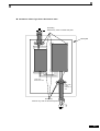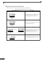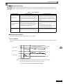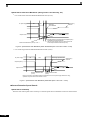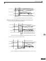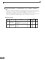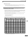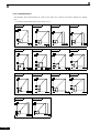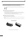
1
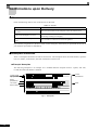
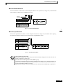
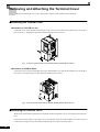
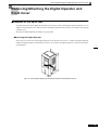
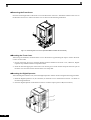
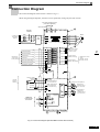
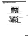
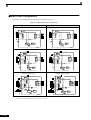
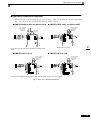
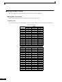
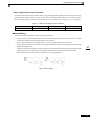
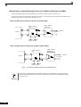
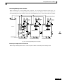
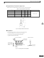
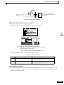
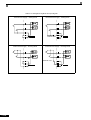
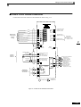
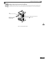
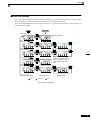
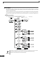
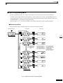
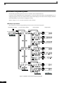
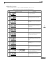
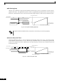
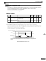
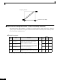
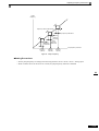
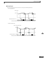
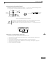
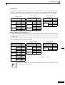
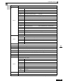
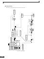
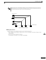
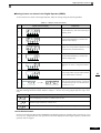
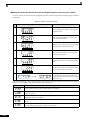
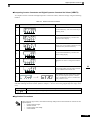
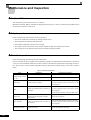
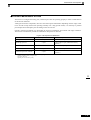
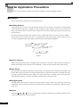
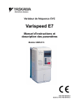
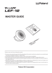
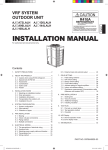
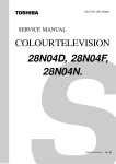
Wiring Main Circuit Terminals Standard Connection Diagrams Standard Inverter connection diagrams are shown in Fig 2.5. These are the same for both 200 V Class and 400 V Class Inverters. The connections depend on the Inverter capacity. CIMR-E7C20P4 to 2018 and 40P4 to 4018 CIMR-E7C2022, 2030, and 4022 to 4055 Braking Resistor Unit (optional) Braking Resistor Unit (optional) Braking Unit (optional) Braking Unit (optional) DC reactor (optional) 3-phase 200 VAC (400 VAC) 3-phase 200 VAC (400 VAC) The DC reactor is built in. Be sure to remove the short-circuit bar before connecting the DC reactor. CIMR-E7C2037 to 2110 3-phase 200 VAC CIMR-E7C4075 to 4160 Braking Resistor Unit (optional) Braking Resistor Unit (optional) Braking Unit (optional) Braking Unit (optional) 3-phase 400 VAC Control power is supplied internally from the main circuit DC power supply for all Inverter models. Fig 2.5 Main Circuit Terminal Connections 2-13