1
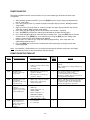
FUNCTION SETUP
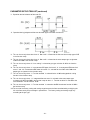
Follow the procedure below to set the functions such as event output type and external switch input
assignments:
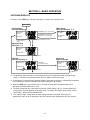
1. After introducing power to the MFC, press the [DISP] key twice (2x) to display the totalized flow
rate (‘L’ lamp lights).
2. Press the [<] key for three (3) seconds or longer (the upper display indicates ‘0.r∩9’ [parameter
setup mode]).
3. Again, press the [<] key for three (3) seconds or longer (the upper display indicates the function
setup item number ‘C-01’ [function setup mode]).
4. Press either the [∧
∧] or [∨
∨] key until the desired setup item number is indicated.
5. Press the [ENT] key (the present setting value indicated on the lower display blinks).
6. Press either the [∧
∧] or [∨
∨] key to select the desired setting value. Press the [ENT] key to store the
selected value. If the [DISP] key is pressed prior to pressing the [ENT] key, the setting value
remains at the previous value without being updated.
7. Repeat steps 4, 5 and 6 for any setup item requiring programming. Once setup items are
completed, proceed to step 8.
8. Press the [DISP] key to return to the instantaneous flow rate display, the display shown after
introducing power.
Note: If no operation is performed for one (1) minute after entering the function setup mode, the display
automatically returns to the instantaneous flow rate display.
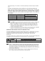
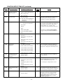
FUNCTION SETUP ITEM LIST
Display
C-01
C-02
C-03
C-04
C-05
Function Description
Key lock
Setup Options and Descriptions
0:
Unlocked
1:
Settings other than flow rate setting
are locked
0
2:
All settings locked
Operating mode
selection (selection by
key operation)
0:
Operating mode selection by key
operation is disabled.
1:
Operating mode selection by key
operation is enabled.
Instantaneous flow rate
setup method
(instantaneous SP setup
method selection)
0:
Digital setup (set by key operation)
1:
Analog setup (set by external
analog voltage input)
Selection of total
number of
instantaneous flow rate
setups (selection of total
number of SP values)
0:
Number of SP values = 1
(SP-0 only)
1:
Number of SP values = 2
(SP-0 and SP-1)
2:
Number of SP values = 3
(SP-0, SP-1 and SP-2)
3:
Number of SP values = 4
(SP-0, SP-1, SP-2 and SP-3)
0:
0 to 5 Vdc input
1:
1 to 5 Vdc input
Setpoint input voltage
range selection, at
analog setting (analog
SP input range
selection)
Factory
Setting
The key lock can be canceled even while it is
enabled.
‘LoC’ is indicated on the display during the keylocked setting.
1
The selection of whether operating mode
selection by key operation (fully
closed/control/fully open) is “enabled” or
“disabled” is available. Refer to instructions for
“Selecting the Operating Mode”.
0
When ‘4: Switching of flow rate setup method’ is
selected at the external switch input function
assignment ‘C-10’ or ‘C-11’, the switching by
external switch input takes precedence.
0
0
- 19 -
Remarks