1
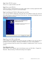
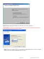
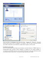
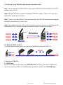
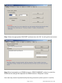
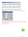
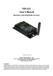
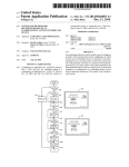
TRP-C51
User’s Manual
Bluetooth To RS232/422/485 Converter
Copyright
Copyright Notice: The information in this manual is subject to change without prior notice in order to improve
reliability, design and function and dosed not represent a commitment on the part of the manufacturer. No part of this
manual may be reproduced, copied, or transmitted in any form without the prior written permission of manufacturer.
Acknowledgment Products mentioned in this manual are mentioned for identification purpose only. Products manes
appearing in this manual may or may not be registered trademarks or copyright of their respective companies.
Page 1 of 17
KSH International CO.,LTD.
1. Introduction………………………………………………………………….………….…………….3
1-1.Features…………..………………………….…………………………………….…….…….…….3
1-2.Specification………………………………………………………………………..…….…………3
2. Hardware Description………….………………………………………………….…….…….…….3
2-1.Panel layout…………………..……..……………………………………………….…………...…4
2-2.LED Indictor…………………………………………………………..……………………………..4
2-3.Serial Connection……………………………………………………………………………..……5
2-4.Power Connection……………………..…………………………………………………………...5
2-5. DIP Switch
………………..……………………………………………………………………....5
2-5-1.The 2-Pin dipswitch for Master/Slave selection ........…………….……………………..…5
2-5-2. The 2-Pin dipswitch for password…….………………………….………………………..…5
2-5-3. Micro touch Button ………..………...……………………………….…………….………..…6
2-5-3-1. Micro touch Button for baud rate setting )………………………………………..……...6
2-5-3-2. Micro touch Button for another device searching ……………………….….…….…...6
2-6. RS232 Pin Wiring…………………………………………………………..………..…..……..….7
2-7. RS485 Wiring ……………….……….…………..………….………….…………..……….……..7
2-8. RS422 Wiring ….....…….………………………………………………….………...…………….7
3.How to use TRP-C51 ………….……….……………………………….…………….…..……....…7
3-1. direct mode …………………………..…………..……………………….…………….………....8
3-2.Point-to-point …………………………………………………………………………….….…….13
3-2-1. How to set up TRP-C51 point-to-point connection mode.…….……………...….……..13
3-3. Build up RS485 Network …………………….…………….………………………..…….…….13
4.How to test TRP-C51……………………………………………………..…………………..……..14
4-1. RS485 test………………………………………………………………………………………….14
4-2. RS232 Loop Back Test ……………………………………………………………….………….15
4-2-1. RS422 hardware wirng connection for loop back test………..…………………….…...15
4-2-2. RS232 hardware wirng connection for loop back test………..……………….….……..15
4-2-3. Loop back test software .………………………………………….……………………..…...15
4-2-4. Start loop back test …………………………………………………………………………....16
Page 2 of 17
KSH International CO.,LTD.
1. Introduction
Based on Bluetooth technology TRP-C51 allows you to wirelessly connect your
RS232/RS422/RS485 devices to systems within the range up to 100M, TRP-C51 is designed for
industrial use it features wide range power input (+10V~30V DC), auto RS232/422/485 signal
switching, access protected by password, internal surge-protection on RS422/485 line. Just plug
it in, set the baud-rate and you are connected, no software or drivers required.TRP-C51 supports
both direct link and point-to-point connection. It can use for wide range of wireless operation and
monitoring process application.
1-1. Features
Bluetooth V1.2 Class 1 compliance. (2.5mW/4dBm)
Transmission coverage up to 100M (300 feet)
Bi-directionally RS485 signal communication and control, compatible to all RS485 devices.
RS422 and RS485 signal auto switching.
16 sets of access password security.
Master/Slave connection mode selectable.
Auto RS232/422/485 signal switching
Distance can be up to 1.2KM by using TRP-C07 repeater.
LED indicators for Power/Link/TX/RX.
Over current , surge protection on RS422/RS485
Power supply: Screw terminal , or external DC adapter (5.5*2.1mm/500mA)
Wide range power input voltage form +10V to +30V DC
1-2. Specification.
Power input voltage : +10V ~+30V
Bandwidth Channel: 79 Channels
RF type Hopping Frequency type(1,600times/sec)
Bandwidth 2.400~2483MHz(ISM band)
Signal: one DB-9 male RS232 connector and 4-wire RS422/485 screw terminal,
Output: RS232: full-duplex (TXD,RXD,,GND).
RS422: Differential 4 full-duplex wires.
RS485: Differential 2 half-duplex wires.
Antenna Type : High Gain Antenna
Baud Rate: From 4800 ~115200bps
Power consumption : 1.2W/500mA
RS422/485 line protection : Against surge, short circuit, voltage peak
Wire : AWG 12 wires
Din-Rail mountable : Yes
Storage temperature : -25~65°C.
Operating temperature : -25~65°C.
Dimension: 151mm X 111mm X 26mm..
Weight : 375g
Page 3 of 17
KSH International CO.,LTD.
2. Hardware Description
The following information is provided to give the user an understanding of how to configure the
TRP-C51 to the USB dongle and point to point mode. An overview of the switchs settings and the
functionality of the LED’s are also provided.
2-1. Panel layout
2-2. LED Indictor
PWR/WDT LED:
When power is supplied to TRP-C51 ,the PWR/WDT LED will on, if the TRP-C51 system is in
Page 4 of 17
KSH International CO.,LTD.
error the LED will blinking.
LINK LED:
Mode.1: Lighting, when the TRP-C51 is properly connected with USB dongle, or connected with
another TRP-C51 (Point To Point) the LED will on.
Mode.2: Baud rate setting indication. When the TRP-C51 is set up the baud-rate the LED flash
will indicate the baud rate status. (refer to 2-6-3-1)
Mode.3: Fast blinking, when TRP-C51 is searching for USB dongle or another TRP-C51, the
LED will fast blinking.
Mode.4: Slow blinking, when power fail or off line which cause TRP-C51 disconnected ,
TRP-C51 will automatically start to re-link , the LED will slow blinking when TRP-C51 re-link..
*In this mode TRP-C51 can’t connect with other device until user push the micro touch button to
reboot the TRP-C51 into searching status (mode.3)
TX LED: RS232/422/485 Transmitting.
RX LED: RS232/422/485 Receiving.
2-3. Serial Connection
The TRP-C51 has one DB-9 male RS232 connector and 4-wire RS422/485 screw terminal,.
2-4. Power Connection
The TRP-C51 has a 2-pin terminal block and power jack. Power can be supplied from either
terminal block or the power jack. It accepts 10-30VDC/500mA power supply. When power is
correctly supplied the PWR LED will start lighting, the system is up and running.
*Please use the power jack specification. (5.5*2.1*12 mm).
2-5. DIP Switch
2-5-1 The 2-Pin DIP-Switch for Master/Slave
SW1: no function.
SW2: Master/slave selecting switch
Turn the SW2 to the “ON” position to set TRP-C51 to be master unit
Turn the SW2 to the “OFF” position to set TRP-C51 to be slave unit
Default setting: SW1 and SW2 are in “OFF” position.
Page 5 of 17
KSH International CO.,LTD.
SW1:NO USE
SW2:ON Master
OFF: Slave
2-5-2 The 4-Pin DIP-Switch for Password
This 4-Pin dipswitch is for TRP-C51 password setting. During TRP-C51 installation the host
system will ask for the TRP-C51 passkey, user may input the password to continue installation. It
is recommended that user set the password before any installation and configuration. Refer to
next there are 16 set of password user may set.
SW-1 SW-2 SW-3 SW-4
PASSWORD
OFF
OFF
OFF
OFF
XGTR
OFF
OFF
OFF
ON
SWIT
OFF
OFF
ON
OFF
PTJL
OFF
OFF
ON
ON
ZUIO
OFF
ON
OFF
OFF
QRTG
OFF
ON
OFF
ON
7UZA
OFF
ON
ON
OFF
3ERT
OFF
ON
ON
ON
QWRT
ON
OFF
OFF
OFF
IOPT
ON
OFF
OFF
ON
SERT
ON
OFF
ON
OFF
YUIT
ON
OFF
ON
ON
FSDF
ON
ON
OFF
OFF
J8QW
ON
ON
OFF
ON
QUTL
ON
ON
ON
OFF
JYH9
ON
ON
ON
ON
1234
2-5-3 Micro Touch button
2-5-3-1. Micro Touch button for Baud-Rate setting
Turn off the TRP-C51’s power then hold the micro touch button down until powered on again.
The LINK LED will regularly flashing. The times of LINK LED flashing indicates different
baud-rate as shown below.
Flash1 time
Flash 2 times
Flash 3 times
Flash 4 times
Flash 5 times
Flash 6 times
4800 bps
9600 bps
19200bps
38400bps
57600bps
115200bps
The default baud rate is 9600bps. If you want to change the baud-rate value, try to push the
micro touch button again, the LINK LED flash 3 times, it means the baud rate is 19200bps.
Page 6 of 17
KSH International CO.,LTD.
Analogically to press micro touch button once again the LED flash 4 times it means the baud rate.
By pressing the micro touch button to set the correct baud rate.
2-5-3-2 Micro Touch button for another device searching.
If TRP-C51 encounters unexpected disconnection such like line-off, or connected device power
fail, The TRP-C51 LINK LED will slow blinking and start auto connection with the failed device,.
meanwhile TRP-C51 will go into “not connectible” stage to reject other device page/inquiry scan..
At this moment If user wants to change the connection to another device, user may push the
micro touch button to activate TRP-C51 back to connectible status and regain the connection.
2-6. RS232 Pin Wiring
2-7. RS485 Wiring
The RS-485 mode supports the Transmit and Receive channels using 2-wire half-duplex
operation.
2-8. RS422 Wiring
The RS-422 mode supports 4 channels full duplex operation for Receive, Transmit, the data lines
are in differential pairs.
Page 7 of 17
KSH International CO.,LTD.
3. How to use TRP-C51
TRP-C51 support direct link mode and point-to-point connection mode.
3-1. Direct mode
User can use the host-pc or Notebook which with integrated bluetooth interface to connect
TRP-C51, after installation the system will generate a COM Port for TRP-C51.
*If host- pc or Notebook does not equip bluetooth interface, you need to add USB dongle as the
connection interface. The approved USB dongle is Ergotech type ET-BD121 that is an optional
accessory for TRP-C51; however TRP-C51 is compatible with most of USB dongle in the market.
User may use own USB dongle for installation or connection.
In the next installation and connection guide we use ET-BD121 as example.
.
Page 8 of 17
KSH International CO.,LTD.
Step.1 Select TRP-C51 as slave.
Refer to 2-6-1, adjust the SW2 to the “OFF”
Step.2 Power on the TRP-C51
TRP-C51 accepts 10-30VDC/500mA power supply. When power is correctly supplied the PWR
LED will start lighting, the system is up and discoverable.
Step.3 Install Bluetooth ET-BD121 USB dongle driver and utility.
User may find ET-BD121 USB dongle driver and utility it the ET-BD121 support CD. Insert the
CD in the CD drive on the PC the driver CD will auto run. The following InstallShield screen
appear. Press Next >to continue
Step.4 Plug in the ET-BD121 USB dongle
In the installation the InstallShield will request user plug in ET-BD121, then user must plug in
ET-BD121 on the PC’s USB port . After plug in ET-BD121 press “Next” to start installation.
The whole process will take few minutes, when installation completed press “Finish” to end the
process.
Step.5 Bluetooth setting
After ET-BD121 driver installed , back to the Windows screen and Click Start – Program file –
Bluetooth – Bluetooth setting. The Bluetooth settings screen appears.
Page 9 of 17
KSH International CO.,LTD.
Step.6 Click on “New connection “ icon into the Add New Connection Wizard the USB dongle
start to search all discoverable TRP-C51 units. Suppose only TRP-C51 unit need to be installed
we can see there is one bluetooth device been searched with the device name TRP-C51. Click
Next> to continue.
Step.7 Select installation mode.
Select Express Mode , or Custom Mode and confirm with Next>
It is recommended that user select the “Custom Mode”, Custom Mode allow user freely to assign
the COM Port to TRP-C51
Page 10 of 17
KSH International CO.,LTD.
Step.8: Assign a appropriate COM port for TRP-C51 and confirm with Next>.
“Auto Connect” means auto connecting when TRP-C51 encounters unexpected disconnection.”
User may choose the function enable or disable.
Step.9: Select the installed TRP-C51 icon and click mouse right button to check or change
options. User may rename or delete the TRP-C51 here.
Page 11 of 17
KSH International CO.,LTD.
Select “Connect” option you are requested a Bluetooth passkey. Please Input TRP-C51
password which must be same as the setting by 4-pin DIP-SWITCH (refer to 2-6-2)”, press OK,
TRP-C51 go into searching mode, the LINK LED start to fast blinking.
Step.10: When TRP-C51 is successfully connected user may see bellowing screen, the LINK
LED stop fast blinking and turn to lighting. TRP-C51 is available to data communication or control.
You also may find TRP-C51 has already added in system device manager.
Page 12 of 17
KSH International CO.,LTD.
User may back to the Windows screen and Click Start – Program file – Bluetooth – Bluetooth
setting to start second TRP-C51 installation. The number of TRP-C51 that a Host server system
may install is depended on the COM Port number that the system or OS can offer.
3-2. Point to point mode
TRP-C51 point-to-point mode allows user wirelessly connection between 2 RS485 devices or
Programmable Logic Controller without changing or resetting all the existing software or
re-configuring your RS485 devices. In this mode the data signal can be auto detected and auto
converting to connect each other. The communicating range can up to 100M.
Page 13 of 17
KSH International CO.,LTD.
3-2-1.How to set up TRP-C51 point to point connection mode
Step.1: Set the password of both TRP-C51 to be same (adjust both 4-pin dipswitch to the same
position (refer to 2-6-2)
Step.2: Set one TRP-C51 as master, and another TRP-C51 as slave. ( refer to 2-6-1 the 2-pin
dipswitch for master/slave selection.)
Step.3: Power on the both TRP-C51 user may see both units LINK LED start to fast blinking that
means they are searching for each other.
Step.4: When both units LINK LED turn to slow blinking and finally become constant lighting that
means both TRPC51 had been mutual connected, the system is ready and workable.
3-3. Build up RS485 network
The RS485 protocol allow user to link maximum 256 RS485 devices with TRP-C51
4. How to test TRP-C51
4-1. RS485 test.
In TRP-C51 support CD user may find “TRPCOM utility” test utility. This utility is designed for
user to test and verify TRP-C51 to RS485 device connection. Double click TRPCOM utility
Page 14 of 17
KSH International CO.,LTD.
Step.1 Select the appropriate COM PORT and baud rate, click OK. You will get the next screen.
Step.2 Send command to your RS485 devices in “SEND COMMAND” column to control the
RS485 devices and get the response from RS485 device in “Response” column
.
User also may conduct loop back test by the wiring connection (refer to point 6-1 and 6-2)
Page 15 of 17
KSH International CO.,LTD.
RS232 TXD(2) and RXD(3) , or RS422 TX+/RX+ and TX-/RX-.
Input data command in “SEND COMMAND” column, the same data will response in the
“Response’ column.
4-2. RS422 and RS232 loop back test.
4-2-1. RS422 hardware wiring connection for loop back test
.
4-2-2. RS232 hardware wiring connection for loop back test.
..
4-2-3 Loop Back Test Software
In TRP-C51 support CD user may find “DEMO.EXE” test utility. This utility is designed for user to
test and verify TRP-C51 to RS232 and RS422 connection status.
4-2-4. Start loop back test.
Step.1 Run the “DEMO.EXE” utility the following screen will be shown
Page 16 of 17
KSH International CO.,LTD.
Step.2 Click the “Setting” to set the RS422 loop counter ,If your system is setting the COM3.
Confirm with “OK”
Please note: “COM3” is an example of COM port number; user may get a different COM port
number after the installation. The actual COM port number is assigned by user or automatically
assigned by Windows system.
Step.4 Click Action to start test.
Page 17 of 17
KSH International CO.,LTD.