1
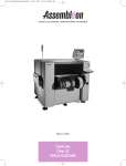
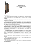
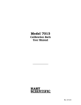
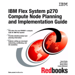
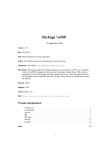
GemLine
TOPAZ
TOPAZ
SPECIFICATIONS
SPECIFICATIONS
October 1998
Philips
Electronic Manufacturing
Technology
Hie r lan gs afsn ijden a.u.b.
Topaz : PA 1309/10
© Philips Electronic Manufacturing Technology B.V. 1998
All rights are reserved. Reproduction in whole or in part is prohibited without the prior written consent of the copyright owner.
The information presented in this document does not form part of any quotation or contract, is believed to be accurate and reliable and
may be changed without notice. No liability will be accepted by the publisher for any consequence of its use. Publication thereof does
not convey nor imply any licence under patent or other industrial or intellectual property rights.
“Values are valid at specified conditions”.
Printed in The Netherlands.
Date of release: October 1998.
9498 386 064 18
Philips
Electronic Manufacturing
Technology
Hie r lan gs afsn ijden a.u.b.
Contents
Contents
1.0
Introducing the Gem Topaz . . . . . . . . . . . . . . . . . . . . . . . . . 3
2.0
General Specifications . . . . . . . . . . . . . . . . . . . . . . . . . . . . . 5
3.0
Features, Accessories and Options . . . . . . . . . . . . . . . . . . . . 8
3.1 Features . . . . . . . . . . . . . . . . . . . . . . . . . . . . . . . . . . . . 8
3.2 Accessories and Options . . . . . . . . . . . . . . . . . . . . . . . 10
4.0
Mounting Heads Configuration . . . . . . . . . . . . . . . . . . . . . 12
5.0
Alignment . . . . . . . . . . . . . . . . . . . . . . . . . . . . . . . . . . . . . 14
5.1 Line Sensor Alignment . . . . . . . . . . . . . . . . . . . . . . . . 14
5.2 Area CCD Alignment . . . . . . . . . . . . . . . . . . . . . . . . 16
5.3 Fiducial Alignment . . . . . . . . . . . . . . . . . . . . . . . . . . . 18
5.4 Bad Mark Sensing & Master Mark Sensing . . . . . . . . 20
6.0
Board Handling . . . . . . . . . . . . . . . . . . . . . . . . . . . . . . . . . 21
7.0
Component Handling . . . . . . . . . . . . . . . . . . . . . . . . . . . . 26
7.1 Feederbar Exchange System
PA 2505/36 . . . . . . . . . . . . . . . . . . . . . . . . . . . . . . . . 26
7.2 LCS Tray Feeder
PA 2699/21 . . . . . . . . . . . . . . . . . . . . . . . . . . . . . . . . 29
7.3 ATS 27 Tray Feeder
PA 2696/20 . . . . . . . . . . . . . . . . . . . . . . . . . . . . . . . . 31
7.4 Mountable Components &
Required Nozzles Gem Topaz . . . . . . . . . . . . . . . . . . 33
8.0
Computer Aided Production Support System (CAPSS) . . . 35
8.1 Introducing CAPSS . . . . . . . . . . . . . . . . . . . . . . . . . . 35
8.2 GPP: Converting CAD Data . . . . . . . . . . . . . . . . . . . 35
8.3 PPS: Program Generation . . . . . . . . . . . . . . . . . . . . . 35
8.4 Line Balancing . . . . . . . . . . . . . . . . . . . . . . . . . . . . . . 36
8.5 PCS: Production Control System . . . . . . . . . . . . . . . . 37
1 of 38
Contents
2 of 38
Introducing the Gem Topaz
1.0
Introducing
the Gem
Topaz
The Topaz is a member of the top-of-the-line GemLine of Philips’ SMD Pick &
Place machines. The Topaz is a flexible, medium volume chip-shooter that can
handle a wide range of components at speeds up to 14,000 SMDs per hour. The
machine is built around a very rigid, vibration-free frame for improved accuracy and
long-term stability and is perfectly suitable for round-the-clock production.
1865 mm
2194 mm
1655 mm
Figure 1
Front view Gem Topaz.
The Gem Topaz features a high precision single placement beam carrying 8 heads
with exchangeable nozzles, one of which is specially designed for high precision QFP
placement. The placement beam moves in X/Y and Z direction, while the board and
component feeders are stationary. A flexible board transport system enables the
Topaz to handle virtually any type of PCB, with or without tooling pins. Board
conveyor width is automatically adjustable, allowing board dimensions up to 457 x
407 mm (18" x 16") to be handled.
The newly designed vision system with line sensor camera allows fast and accurate
“on-the-fly” alignment of a wide range of components from 0402 up to 25 mm
square PLCC, including 21 mm square ICs with lead pitches down to 0.65 mm (25
mil).
3 of 38
Introducing the Gem Topaz
An optional area CCD camera, in combination with the precision head, extends the
component range to 32 mm square ICs with lead pitches down to 0.5 mm (20 mil).
The vision system detects missing, bent or irregular spaced leads or BGA balls; faulty
components are rejected.
A separate camera system monitors fiducial marks at board, circuit and component
level, using white-light LEDs and multi-angle diffusers to provide optimal
illumination.
Just five nozzle shapes are required to cover the specified SMD range. High output
levels are therefore achieved, as the need for nozzle exchanges is minimal. An
optional 12 position nozzle exchange station enables additional special nozzles to be
accommodated.
Up to 100 tape feeders can be loaded on the Gem Topaz. The machine supports
tape, stick, bulk and tray feeders. The tape feeder design for the Gem Topaz allows
simultaneous picking from any mix of tape feeders ranging from 8 to 56 mm.
An industrial PC controller, running Philips’ well proven and user-friendly software,
allows the Gem Topaz to be used stand-alone or in-line. The controller includes a
Management Information System (MIS) that continuously gathers production data
for management feedback. The unique bad mark sensing capabilities allow a multicircuit panel to be run as one large board, thus maximizing placement speed while
still using bad mark information.
A basic program optimization function is included in the machine as standard. For
more advanced machine optimization and/or line balancing, the off-line Philips
Computer Aided Production Support System (CAPSS) is available.
The Gem Topaz is fully compatible with the Sapphire and Emerald, which use the
same feeders, feederbars, software and controller. A laser-based verification system,
which guarantees correct feeder latching, is standard. Off-line feeder changeover can
be achieved by using a Feederbar Exchange System (FES). An entire feederbar can be
conveniently loaded off-line, minimizing change-over time. An optional Set-up
Verification System (SVS) guides the operator through placing the appropriate
components at the correct supply position. A scanner checks the barcode on the reels
and sticks, while sensors in the feederbars verify the correct feeder location.
4 of 38
General Specifications
2.0
General
Specifications
Gem Topaz
Optimal placement rate:
Nominal placement rate:
Applicable Components:
Mounting accuracy:
(x,y) 3σ
Mounting angle:
Alignment system:
Type of nozzles:
Nozzle exchange station:
Number of heads:
Placement heads
actuation method:
Number of feeders:
14,000 cph
9,000 - 11,000 cph
0402 - SOP, SOJ, PLCC 25 mm (1.0")
QFP 21 mm (0.83") with pin pitch down to 0.65 mm (25 mil)
QFP 32 mm (1.26") with pin pitch down to 0.5 mm (20 mil)
Max. component height: 6.5 mm
0.08 mm for chips and SOIC
0.06 mm for QFPs
0 up to ± 180 (steps of 0.01)
Line sensor camera with fore light system for Vision-on-the-Fly;
image processing by VICS 2500 proprietary vision system
Area CCD camera for fine pitch components
Area CCD camera for fiducial alignment
Type 31
Type 31-1 (Precision Head only, spring loaded)
Type 32-2
Type 33
Type 34
Type MELF
12 nozzle positions
One single beam with 8 exchangeable nozzles
Pneumatic or servo controlled for component height compensation
Tapefeeders:
8 mm: 100 positions
12 mm: 48 positions
16 mm: 48 positions
24 mm: 32 positions
32 mm: 32 positions
44 mm: 24 positions
56 mm: 18 positions
Stick feeders: Depends on stick dimensions
Bulk feeders: 100 x 8 mm positions
REMARKS
Simultaneous pick
Line sensor camera system
Line sensor camera system
Optional area CCD camera system
Line sensor camera system
Using Precision Head and optional
area CCD camera system
Second Line sensor camera for
rear side is optional (Max. Board
width is limited to 300 mm (11.8")
Optional
Standard
The nozzle types for Topaz and
Emerald are the same. Standard
will be delivered: 7x nozzle 31,
1x nozzle 31-1, 2x nozzle 32-2,
1x nozzle 33,
1x nozzle 34, 1x nozzle MELF
Optional (No nozzles included)
Including one Precision Head
5 of 38
General Specifications
Gem Topaz
Component Packaging:
Tape according to IEC/EIA-J/JEDEC: 8-56 mm
Manual Tray feeder:
Max. tray size 320 mm x 320 mm (12.6" x 12.6")
Fixed Manual Tray Feeder:
Max. tray size 635 mm x 136 mm (25" x 5.3")
For other Multi-Manual Tray Feeder options, please contact
your local sales representative
ATS 27 Tray Feeder:
Max. tray size 364 mm x 222 mm (14.3" x 8.7")
Maximum height premounted components:
PCB Dimensions (x,y):
LCS Tray Feeder:
Max. tray size 350 mm x 468 mm (13.7" x 18.4")
Stick and bulk
6.5 mm on placement side (0.26")
15 mm on non-placement side (0.6")
Min: 50 mm x 50 mm (2.0" x 2.0")
Max: 457 mm x 407 mm (18" x 16") using PCB pin fixation
Max: 440 mm x 407 mm (17.3" x 16") using PCB edge clamping
system
PCB Thickness:
Non-mountable area:
PCB Material:
PCB Positioning:
Min. 0.6 mm (0.02")
Max. 3.0 mm (0.12")
Board Top side:
3 mm from rear side board edge (0.12")
0 mm from front side board edge
3 mm around reference holes (0.12") (locate pins)
Board bottom side:
5 mm from front and rear side board edge (0.2")
For Ceramic boards (optional) the non-mountable area can be
different
Phenolic/FR4/Composite Materials
Locate pin fixation
Push up pins
Edge clamping
Sub stop (PCB waiting buffer)
PCB Transport height:
900 mm ± 10 mm (35.4" ± 0.4")
SMEMA 953 mm ± 12.5 mm (37.5" ± 0.5")
PCB Transport direction: Left to Right
6 of 38
REMARKS
Tape reel diameter max: 380
mm (15")
Optional: Manual tray feeder
(Second line sensor camera not
possible; amount of rear side
feeder positions limited)
Optional: Fixed manual tray
feeder (Max. board size 250 mm
(10"); second line sensor camera
not possible)
Optional: ATS 27 tray feeder (Max.
board size 250 mm (10"); second
line sensor camera not possible
Optional: LCS tray feeder
(no restrictions)
Optional 558 mm x 508 mm (22" x
20"). However, Line sensor camera & nozzle station mounted at
machine REAR side. No second
line sensor camera possible.
Amount of rear side feeder positions limited. Special LCS required.
Special applications upon request
Component height restrictions
apply in the 10 mm (0.4") area
from front side edge depending
on board thickness
Ceramic boards require special
conveyor sections (optional)
Adjustable
Adjustable
Adjustable
Adjustable
Standard
Standard
Right to Left is optional
General Specifications
Gem Topaz
PCB Transport width:
Automatic
PCB Loading time:
Approximately 3 sec.
PCB Ratio width/length:
Control system:
Max. 1:3
MCX controller 486-100
40 Mb flash disk
1.44 Mb floppy drive 3.5"
RS 232 Serial Interface
15" Color Monitor
9" Black/White vision monitor
VIOS (Visual Integrated Operating System)
Hand held keyboard for all operator functions
Enhanced PC/AT keyboard for data editing functions
Max. 127 PCBs
Backup and restoring data using RS232 serial line or floppy
Data conversion UFOS↔VIOS
Data conversion Text↔VIOS
MIS data gathering
Data teaching
Data tracing
Component database
Mark database
SMEMA electrical interface
On line calibration
On line help functions
Feeder lock verifier
Length: 1655 mm (5.4 ft)
Height: 1865 mm (6.1 ft)
Width: 1358 mm (4.5 ft)
User Interface:
Control system functions:
Machine dimensions
and weight:
Safety standards:
Weight: 1150 kg (2535 Lbs)
Optional mechanical safety package
Electrical safety according IEC 204
Electric Power:
Voltage AC: 200/208/220/240/380/400/416 V ± 10%, 3 Phase
REMARKS
Front rail fixed
Rear rail adjustable
PCB loading concurrent to SMD
picking and alignment
100 MHz, 16 Mb intern. memory
Optional 85 Mb
2280 comp/PCB
1000 Component packages
300 Mark shapes
Width including feeders 2194
mm (7.2 ft)
This option is necessary to
comply with the European CE
safety regulation
More than 2.5 mm2 cables are
needed
Frequency: 50/60 Hz
Consumption: 4 kVA max.
Air supply:
Operating temperature:
Humidity:
Pressure: > 5.105 Pa (5 bar, 72.5 PSI)
Quality: dust and oil free
Consumption: 350 Nl/min.
20 - 30°C (68 - 86°F)
35 - 90% (no dew)
Table 1
7 of 38
Features, Accessories and Options
3.0
Features,
Accessories
and Options
3.1
Features
The standard Gem Topaz includes the following features:
• On the fly alignment using a vision system with a line sensor camera.
• Placement beam with seven standard heads and one Precision Head.
• Simultaneous picking is possible by all 8 heads from any mix of tape feeders. This
allows a much higher nominal placement rate and board throughput.
• Handling of complete component range with only 5 nozzles shapes.
• Robust fiducial alignment camera, also used for teaching/tracing and Bad Mark
Sensing.
• Automatic width adjustment. The PCB dimensions are part of the PCB data.
• PCB pin-positioning. Second pin is easily adjustable for fast changeover.
• PCB edge clamping system, for PCB's without tooling holes.
• PCB push up plate with 12 push up pins, for PCB support.
• Substop, allowing a second PCB to enter the machine for reducing transport
time.
• Feeder lock verification system to avoid damage to the machine due to incorrectly
latched feeders.
• Backup and restoring data using RS 232 serial line or 3.5" FDD
• Component dump box.
• Operator manual, available in several languages.
• User manual.
• Service manual.
• Two empty tape bins.
• Toolset.
• First aid spare parts kit.
• CE safety.
• ESD safety.
• Electrical and Mechanical SMEMA.
8 of 38
Features, Accessories and Options
Standard Software features:
• Easy-to-use VIOS (Visual-Integrated-Operating-System) user interface.
• On-line help function with detailed descriptions of operations and functions on
screen.
• Management Information System (MIS) to gather production history data.
• 4 point fiducial correction, to maintain accuracy for stretched/distorted boards.
• Fiducial template matching for PCBs that have no fiducials. (art work
recognition)
• Different mark for fiducial pair.
• Fiducial teaching recovery function to allow measurement of damaged fiducials
without taking the board(s) out of the machine.
• Data editing functions with the use of the fiducial camera (teaching,tracing).
• A Component Database, that can hold up to 1000 component packages, with the
most frequently used components already predefined.
• A Mark Database, that can hold up to 300 mark shapes, with the most frequently
used mark shapes already predefined.
• Pre picking, allowing to pick up of components, while the board is being
transported practically eliminating board transfer time.
• Alternative feeder function, reducing operator intervention (empty feeder
switching).
• Automatic program change over for family boards (self production control).
• Automatic rework cycle to improve operator efficiency including online
optimisation which skips empty feeders automatically.
• On-line product preparation and basic program optimization (nozzle and feeder
set-up).
• Multi-cirquits PCBs can be either be mounted block-by-block or the whole panel
can be treated as one single large board by combining the block data. By
combining block data, the optimal mounting sequence can be achieved, while the
use of block bad marks remains in effect by using sophisticated software.
9 of 38
Features, Accessories and Options
3.2
10 of 38
Accessories
and Options
ACCESSORIES AND OPTIONS TOPAZ
PA 1912/00
CSM/Gem Glass Adjustment Kit
PA 2505/35
Feederbar exchange system one side factory built in
(define rear or front), included FES 50 position cart for
FV/GEM
PA 2505/36
FES (Feeder bar exchange) cart 50 position
PA 2505/38
FES head protection unit (only one per machine needed)
PA 2505/39
Modification kit FES 50 position (field retro fit)
PA 2695/11
Manual Tray Feeder GEM
PA 2695/15
Fixed Manual Tray Feeder
PA 2696/20
ATS 27 Tray Feeder for GEM (factory built in at rear side)
PA 2699/21
LCS Tray Feeder for Topaz, Emerald, Eclipse II
PA 2903/20
16 mm Tape Feeder, 15 inch reelholder FV/GEM
PA 2903/30
24 mm Tape Feeder, 15 inch reelholder FV/GEM
PA 2903/40
32 mm Tape Feeder, 15 inch reelholder FV/GEM
PA 2903/50
44 mm Tape Feeder, 15 inch reelholder FV/GEM
PA 2903/74
8 mm Tape Feeder, 2 mm pitch, 7 inch reelholder FV/GEM
PA 2903/75
8 mm Tape Feeder, 4 mm pitch, 7 inch reelholder FV/GEM
PA 2903/76
8 mm Tape Feeder, 4 mm pitch, 15 inch reelholder FV/
GEM
PA 2903/80
12 mm Tape Feeder, 7 inch reelholder FV/GEM
PA 2903/81
12 mm Tape Feeder, 15 inch reelholder FV/GEM
PA 2923/00
Set of 20 dummy feeders
PA 2962/72
Nozzle Type 32-2
PA 2962/73
Nozzle Type 33
PA 2962/74
Nozzle Type 34
PA 2962/75
Nozzle Type 31
PA 2962/76
MELF Nozzle
PA 2962/78
Nozzle Type 31-1 Topaz head one (spring loaded)
PA 2963/15
Nozzle Exchange System Topaz (12 position/no nozzles
incl.)
Features, Accessories and Options
PA 2969/50
Second line sensor camera for Topaz
PA 2969/90
Area CCD camera (including forelighting) for Topaz
PA 2981/10
Pallet for LCS Tray Feeder FV/GEM
PA 2981/30
Pallet for PA 2696/20 (ATS 27)
FV indicates Comet I/II, Eclipse I/II and Orion family of machines
Table 2
11 of 38
Mounting Heads Configuration
4.0
Mounting
Heads
Configuration
Figure 2
The Gem Topaz features a high precision placement beam carrying 8 heads with
exchangeable nozzles, one of which is specially designed for high precision QFP
placement and a separate camera system that monitors fiducial marks at the board,
circuit and component level, using white-light LEDs and multi-angle diffusers to
provide optimal illumination. High placement rates are achieved by simultaneous
component picking which reduces head beam travel and thus shortens the mounting
cycle.
Configuration of head section.
The high-precision Topaz features four-axis (X,Y,Z,R) servo control for accurate,
stress-free component mounting. Direct Drive, brushless AC motors controlling
heavy duty lead screws allow optimal accuracy and superb reliability.
12 of 38
Mounting Heads Configuration
SPECIFICATIONS
Applicable Components:
0402 - SOP, SOJ, PLCC 25 mm
(1.0")
QFP 21 mm (0.83") with pin pitch down to
0.65 mm (25 mil), using line sensor camera
QFP 32 mm (1.26") with pin pitch down to
0.5 mm (20 mil), using optional area CCD
camera
Mounting accuracy (x,y) 3σ:
0.08 mm for chips and SOIC with line sensor
camera
0.06 mm for QFPs using precision head and
optional area CCD camera system
Placement tact time:
0.3 sec for 8 x nozzle type 31 (chips)
0.65 sec for 4 x nozzle type 32 (SO ICs)
Encoder resolution:
X,Y = 2.5 µm
Phi = 0.009°
Head position repeatability:
X = 0.010 mm
Y = 0.010 mm
Speed:
X = 1500 mm/sec
Y = 1500 mm/sec
Acceleration:
X = 31000 mm/sec2
Y = 19000 mm/sec2
Table 3
13 of 38
Alignment
5.0
Alignment
5.1
Line Sensor
Alignment
The high speed of the Gem Topaz is achieved by fast on-the-fly component
alignment using a revolutionary line sensor system that is four times faster than
conventional systems. For ultimate speed, the machine can be equipped with a
second line sensor camera which reduces head beam travel and thus shortens the
mounting cycle.
encoder
head
motor
spindle
components
camera
pixels
monitor
picture
components
Figure 3
Line sensor vision principle.
While moving the beam over the camera, the encoder triggers the camera to capture
consecutive lines of pixels. All these lines form the total picture of the components.
This picture is processed by a sophisticated vision system. The vision system
algorithms inspect the components and calculate position and orientation of the
components on the heads.
The SMD components are illuminated by fore lighting/reflective lighting. The leads
of the components are imaged on the line sensor.
14 of 38
Alignment
SPECIFICATIONS
Line sensor camera:
CCD 2048 x 1 pixels
Max. component size:
25 mm
Min. component size:
0402
Min. lead pitch:
0.65 mm (25 mil)
Min. lead width:
0.2 mm (0.004")
Grey scale:
256 levels
Lighting:
Fore lighting (red LED array)
Recognition:
Reflection. Pattern recognition on all leads
Max. nr lead sides:
4
Max. nr lead groups:
2 per side
Check on:
Lead pitch
(1.0")
Lead location
Bent/missing leads
Total number of leads
Cumulative lead pitch
Applicable components:
0402 - SOP, SOJ, PLCC 25 mm
(1.0")
QFP 21 mm (0.83") with pin pitch down to
0.65 mm (25 mil)
Irregularly shaped SMDs like CONNECTOR
TSOP / VSOP
Component definition:
Physical data entry (from data sheet)
Table 4
15 of 38
Alignment
5.2
Area CCD
Alignment
An optional area CCD camera extends the component range for the Gem Topaz
Precision Head.
Component illumination is performed by means of fore lighting/ reflective lighting.
Fore lighting reflects the lead of QFP and the balls of BGA components on the CCD
camera. The area CCD camera grabs the image of the component in one frame and
presents it to the vision system for recognition and measurement purposes.
Figure 4
Gem Topaz working area.
SPECIFICATIONS
16 of 38
Area CCD Camera:
CCD 512 x 480 pixels
Max. component size:
32 mm
Min. component size:
6 mm
Min. lead pitch:
0.5 mm (20 mil)
Min. lead width:
0.2 mm (0.008")
Grey scale:
256 levels
(1.26")
(0.24")
Alignment
SPECIFICATIONS
Lighting:
Fore lighting (red LED array)
Recognition:
Reflection. Pattern recognition on all leads
Max. nr lead sides:
4
Max. nr lead groups:
2 per side
Check on:
Lead pitch
Lead location
Bent/missing leads
Total number of leads
Cumulative lead pitch
Total BGA balls
Applicable components:
QFP 32 mm (1.26") with pin pitch down to
0.50 mm (20 mil)
CONNECTOR
Only dark background BGAs max. 32 mm
with min. ball pitch 1.27 mm (50 mil)
Component definition:
Physical data entry (from data sheet)
Table 5
17 of 38
Alignment
5.3
Fiducial
Alignment
The Gem Topaz is standard equipped with a fiducial camera. This camera is used to
compensate for variations in the position of the circuit pattern relative to the
expected position. The fiducial alignment system is an opto-electronic system which
performs geometric measurements of fiducial marks on the PCB in order to calculate
the deviations from their expected positions. The system can use two or four
fiducials per board. Each subcircuit can also be aligned using two fiducials. For
placement of fine-pitch components two local fiducials per component may be used.
The individual shapes of a fiducial pair can be different to allow for maximum
application flexibility.
SPECIFICATIONS
Fiducial camera:
CCD
Fiducial illumination:
White-light LEDs in conjunction with a multiangle illumination
Compensation for:
(with two fiducials)
Translation
Rotation
Linear stretch and shrink
Compensation for:
(with 3 or 4 fiducials)
Non-linear stretch and shrink
Type of compensation:
PCB, Block, Local
Fiducial size:
Max. 3.0 mm (0.12")
Min. 0.8 mm (0.03")
Table 6
18 of 38
Fiducial material:
Copper
Gold
Lead-tin
Fiducial clearance area
2 x Fiducial size
PCB warpage at fiducial:
Max. 0.5 mm (0.02")
Pattern offset:
Max. 1 mm (0.04")
Number of different Fiducial pairs per PCB:
128
Number of fiducial shapes in Mark Database:
300
Examples of fiducials:
Solid circle (preferred)
Square
Triangle
Donut
Binary cross
Bow-tie (connected)
Template matching (art work)
Fiducial definition:
According CAD data
Alignment
A
2A
Figure 1
Fiducial free space.
Figure 2
Examples of fiducials.
Figure 3
Examples of PCB, block and local fiducials.
19 of 38
Alignment
5.4
Bad Mark
Sensing &
Master Mark
Sensing
If the PCB contains subcircuits, one or more of these subcircuits can be skipped for
placement by giving them a “Bad Mark” on a designated position on the subcircuit. No
parts will be placed on a circuit that has a Bad Mark. Bad Mark sensing, with the use of
the fiducial camera, is based on recognition of a difference in contrast in a certain
area. This area can be defined in the machine software (position and areadimensions). This gives maximum freedom in choosing the process or technique to
add Bad Marks, for example:
• white or light colored labels of any dimension,
• white paint,
... or any other material that can be fixed as long as it contrasts with the PCB surface.
Before checking the Bad Marks on all circuits, the Master Mark may be checked
first. Presence of a Master Mark means that one or more Bad Marks are present on
the circuits. This allows the machine to skip the Bad Mark sensing process for all
circuits if no Bad Marks are located on the circuits, therefore saving valuable
production time.
20 of 38
Board Handling
6.0
Board
Handling
PCB boards can be located in the machine by either tooling pins or edge clamping if
tooling holes are not available. With Pin location, one location pin is fixed on the
machine while the other locate pin is easily adjustable when the board length
changes. Change over to a different board size is just a matter of seconds.
Figure 5
Pin fixation system.
Figure 6
Push up system.
21 of 38
Board Handling
The Edge Clamping system is as easy to adjust as the locate pin fixation. Both these
systems use Push-up pins to support the PCB.
Figure 7
Gem Topaz Edge Clamping system.
A Sub-stop enables an additional PCB to enter the machine while the current board
is being populated. This reduces time loss during transport and is very useful when
operating the machine in a flowline.
When using the machine in a flowline, it communicates with the unit upstream and
downstream over a SMEMA-connection.
PCB Dimensions (x,y):
PCB Thickness:
Reference hole position:
Reference hole diameter:
22 of 38
SPECIFICATIONS
Min. 50 mm x 50 mm (2.0" x 2.0")
Max. 457 mm x 407 mm (18" x 16") using PCB
pin fixation
Max. 440 mm x 407 mm (17.3" x 16") using
PCB edge clamping system
Optional 558 mm x 508 mm (22" x 20").
For this option, line sensor camera, nozzle station mounted at machine REAR side. No front
line sensor camera possible. Amount of rear
side feeder positions is limited.
Min. 0.6 mm (0.02")
Max. 3.0 mm (0.12")
5 mm (0.2") in X and Y from lower right corner
Ø 2.0 mm-Ø 4.0 mm (0.08" - 0.157")
Board Handling
SPECIFICATIONS
0.5 mm up (0.02")
1.0 mm down (0.04")
Max. height pre-mounted components:
6.5 mm on placement side (0.26")
15 mm on non placement side (0.6")
Non-Mountable area:
Board Top side:
3 mm from rear side board edge (0.12")
0 mm from front side board edge (Component
height restrictions apply in the 10 mm (0.40")
area from front side edge depending on board
thickness)
3 mm around reference holes (0.12") (locate
pins)
Board Bottom side:
5 mm from front and rear side board edge
(0.2") For Ceramic boards (optional) the nonmountable area can be different
PCB Material:
Phenolic/FR4/Composite Materials
Ceramic boards require special conveyor sections (optional)
PCB positioning:
Locate pin fixation
Push up pins
Edge clamping
Sub stop (PCB waiting buffer)
PCB Transport height:
900 mm ± 10 mm (35.4" ± 0.4")
SMEMA 953 mm ± 12.5 mm (37.5" ± 0.5")
PCB Transport direction:
Left to Right
PCB Transport width:
Automatic
PCB loading time:
Approximately 3 sec.
PCB ratio width/length:
Max. 1:3
PCB Maximum warpage:
Table 7
23 of 38
Board Handling
L
3 mm (0.12")
W
10 mm
(0.4")
B
A
5 mm (0.2")
5 mm
(0.2")
5 mm (0.2")
- Not mountable area
- Mounting is not possible within 3 mm (0.12")
of the periphery of the A (positioning hole)
and the B (long hole), and from rear side Board Edge
- Locate pin restriction. Component height restrictions apply in the
10 mm (0.4") area from side edge depending on Board thickness
Figure 8
Mountable area.
Max. 0.5 mm (0.02") *
Max. 1.0 mm (0.04")
* In this case components to be mounted
not to exceed 6 mm (0.24")
Figure 9
24 of 38
Warp of fixed PCB.
Board Handling
Figure 10
Mountable area.
25 of 38
Component Handling
7.0
Component
Handling
7.1
Feederbar
Exchange
System
PA 2505/36
Figure 11
The Feederbar Exchange System (FES) allows fast change-over by switching the
complete feederbar.
FES carriage.
Feederbars are mounted on carts to allow for off-line feeder set-up. These carts are
easily moved from set-up area to the mounting machines and back. This option is
available for the front and rear side of the machine without loss of feeder positions or
any other technical restrictions. To prevent any damage during feederbar exchange, a
FES head protection unit permits feederbar exchange only when the head assembly
is parked in the middle of the machine.
Topaz FES carts are compatible with those of the Emerald and Sapphire. An empty
tape bin will be delivered with each FES cart.
26 of 38
Component Handling
FES SPECIFICATIONS
FES 50 position
FES change over time:
≤ 60 sec
FES repeatability:
Pick position ≤ 0.15 mm
Applicable feeders:
Tape, stick, bulk feeders
Number of feeders
on FES cart:
8 mm:
50 positions
12/16 mm: 24 positions
24 mm:
16 positions
32 mm:
16 positions
44 mm:
12 positions
56 mm:
9 positions
Stick:
depends on stick dimensions
Electrical interface:
Round 72 pin connector
Electrical power:
Supplied by main system
Pneumatic interface:
Quick connect coupling
Air supply:
Supplied by main system
FES dimensions, stand alone without feeders: Length: 1070 mm (3.5 ft)
Width: 650 mm (2.1 ft)
Height: 920 mm (3.0 ft)
Weight without feeders:
76 kg (167 Lbs)
Mechanical items:
Feederbar for 50 x 8 mm feeders
Cast iron feederbar frame
Cast iron trolley
Compatibility:
CSM Orion, CSM Eclipse II, Gem Emerald
The FES specifications are valid for the use at SMEMA height.
Table 8
27 of 38
Component Handling
28 of 38
Figure 12
FES interface.
Figure 13
Interface box with pin connector and a pneumatic quick connect coupling.
Component Handling
7.2
LCS Tray
Feeder
PA 2699/21
The LCS Tray Feeder is an additional pallet sequencer feeding parts from a tray. This
feeder can be equipped with a maximum of 50 pallets, each being able to hold
different trays.
1
MAGAZINE
2
MAGAZINE
Figure 14
LCS Tray Feeder.
Two or three components are picked up from the tray and placed on a shuttle. This
shuttle transports the components into the machine for pick-up and mounting by
the placement heads.
The cycle time of the Tray feeder is 5.0 seconds for 3 parts when using the same tray
and 6.5 seconds when changing the tray. However, in practice no time is lost because
of the simultaneous operation of Tray Sequencer and Topaz: while the machine is
picking from on-board feeders, the shuttle brings in new components.
A part rejected by vision will be placed back on the shuttle and returned to its orginal
tray position; this means no loss of expensive parts.
• The PCB buffer conveyor on the Tray Feeder offers the possibility for visual PCB
inspection and allows linking with downstream machines.
• The tray container is separated into two sections with each 25 pallets. This allows
tray replenishment while the machine is running.
29 of 38
Component Handling
LCS TRAY FEEDER SPECIFICATIONS
GENERAL
Max. Tray size (L x W):
350 mm x 468 mm (13.7" x 18.4")
Cycle time:
5.0 sec. for 3 parts (picking from same tray)
6.5 sec. for 3 parts (picking from two trays)
However, in practice no time is lost because
of the simultaneous operation of Tray
Sequencer and Topaz: while the machine is
picking from on-board feeders, the shuttle
brings in new
components
Power and air supply:
Delivered by Topaz
LCS Tray feeder dimensions:
Length: 773 mm (2.5 ft)
Height: 1165 mm (3.8 ft); with top cover open
1520 mm (5.0 ft)
Width: 1595 mm (5.2 ft); with door open
2175 mm (7.1 ft)
Topaz + Tray feeder dimensions:
Length: 2423 mm (8.0 ft)
Height: 1865 mm (6.1 ft)
Width: 1818 mm (6.0 ft); with LCS door open
and feeders on Topaz 2791 mm (9.2 ft)
Weight:
± 250 kg (551 Lbs)
APPLICABLE COMPONENTS
Min. Component dimension:
8 mm x 8 mm (0.31" x 0.31") Mold size
Max. Component dimension:
54 x 54 mm (2.1" x 2.1")
Max. Tray height included component height:
6 mm (0.24") from pallets at pitch of 10 mm
(0.4"), total 50 pallets possible
Max. Tray height included component height:
16 mm (0.63") from pallets at pitch of 20 mm
(0.79"), total 26 pallets possible
FEED CAPACITY
Nozzles on shuttle:
3
STANDARD COMPONENT CAPACITY
Table 9
30 of 38
Max. number of component types:
150
Number of pallets:
Standard 40 pallets included (additional pallets
available PA 2981/10)
Component Handling
7.3
ATS 27
Tray Feeder
PA 2696/20
Figure 15
The ATS 27 Tray Feeder is a new additional internal pallet sequencer, allowing highspeed feeding of tray components. This feeder can be equipped with a maximum of
27 pallets, each being able to hold different trays.
ATS 27 Tray Feeder.
The maximum pallet exchange time for the ATS 27 Tray feeder is 5.0 seconds.
However, in practice no time is lost because of the simultaneous operation of the
ATS 27 Tray Sequencer and Topaz; while the machine is picking from on-board
feeders, the pallet brings in new components.
A part rejected by vision will be placed back in its original tray position; this means
no loss of expensive parts.
31 of 38
Component Handling
ATS 27 TRAY FEEDER SPECIFICATIONS
GENERAL
Max. Tray size (L x W):
364 mm x 222 mm (14.3" x 8.7").
Pallet exchange time:
Changing from pallet 1 to 27; 5 seconds
However, in practice no time is lost because
of the simultaneous operation of the ATS 27
Tray Sequencer and Topaz; while the machine
is picking from on-board feeders, the pallet
brings in new components.
Power and air supply:
Delivered by Topaz.
Topaz + ATS 27 Tray feeder dimensions:
Length: 1655 mm (5.4 ft)
Height: 1865 mm (6.1 ft)
Width: 1761 mm (5.8 ft);
with ATS 27 door open: 2267 mm (7.4 ft)
Maximum board size Topaz:
250 mm (9.8") and no second line sensor camera possible
APPLICABLE COMPONENTS
Max. Tray height included component height:
6 mm (0.24") from pallets at pitch of 10 mm
(0.4"), total 27 pallets possible.
Max. Tray height included component height:
16 mm (0.63") from pallets at pitch of 20 mm
(0.79"), total 13 pallets possible.
STANDARD COMPONENT CAPACITY
Number of pallets:
Table 10
32 of 38
Standard 20 pallets included (additional pallets
available PA 2981/30)
Component Handling
7.4
Mountable
Components
& Required
Nozzles
Gem Topaz
Just five nozzle shapes are required to cover the specified SMD range. High output
levels are therefore achieved, as the need for nozzle exchanges is minimal. An
optional 12 position nozzle exchange station enables additional special nozzles to be
accommodated.
COMPONENTS
L
Solid resistor
REQUIRED
NOZZLE
DIMENSION (mm)
W
T
1.00
0.50
0.50
Type 31
1.60
0.80
0.50
Type 31
2.00
1.25
0.50
Type 31
3.20
1.60
0.60
Type 31
2.00
ø 1.25
Type 31
3.45
ø 1.35
Type 31
1.50
0.80
0.80
Type 31
2.00
1.25
1.25
Type 31
3.20
1.60
1.25
Type 31
3.20~4.50
2.50~3.20
1.50~1.90
Type 31
5.60
5.00
1.90
Type 32-2
T
L
W
Solid resistor
L
∅
Multi-Layered ceramic
capacitor
T
W
L
L
MELF ceramic
capacitor
3.40
ø 1.50
MELF
Tantalium electrolytic
capacitor
2.90
1.60
1.60
Type 31
3.80
2.90
1.60
Type 31
4.70
2.60
2.10
Type 31
6.00
3.20
2.50
Type 32-2
7.30
4.30
2.80
Type 32-2
Aluminium electrolytic
capacitor
4.3
4.3
5.7
Type 32-2
6.6
6.6
5.7
Type 32-2
Chip film capacitor
7.3
5.3
3.25
Type 32-2
∅
T
W
L
T
L
W
T
W
L
33 of 38
Component Handling
COMPONENTS
L
Chip inductor
REQUIRED
NOZZLE
DIMENSION (mm)
W
T
3.2
2.5
2.0
Type 31
4.5
3.2
3.2
Type 32-2
Semi-variable
resistor
4.5
3.8
2.4
Type 32-2
Transistor (SOT)
2.90
1.5
1.10
Type 31
4.0
3
1.8
Type 32-2
Power transistor
4.6
2.6
1.6
Type 32-2
SOP (6 ~ 28 pin)
5.00
4.50
1.50
Type 32-2
10.10
4.50
1.50
Type 32-2
12.60
5.70
1.50
Type 32-2
15.30
7.50
2.00
Type 32-2
17.80
7.50
2.00
Type 32-2
T
L
W
T
L
W
T
L
W
W
T
L
W
L
T
PLCC
QFP
BGA
SOJ (20 ~ 42 pin)
TSOP (20 ~ 32 pin)
Table 11
34 of 38
6~12.5 (below 1.1 g)
Type 32-2
10~25 (below 2.0 g)
Type 33
18~45 (below 6.2 g)
Type 34
6~14 (below 0.6 g)
Type 32-2
8~25 (below 2.0 g)
Type 33
18~45 (below 5.3 g)
Type 34
max.
21
Type 33
max.
32
Type 34
max.
21
Type 32-2
max.
32
Type 33
max.
30
Type 32-2
Type 33
Type 34
Computer Aided Production Support System (CAPSS)
8.0
Computer
Aided
Production
Support
System
(CAPSS)
8.1
Introducing
CAPSS
Philips’ Computer Aided Production Support System consists of a powerful set of
software modules designed to reduce the time required to bring products from
design to production. CAPSS is a reliable approach to support the flexible structure
of a Philips SMD assembly line.
8.2
GPP:
Converting
CAD Data
The GPP is a template based tool which converts/combines CAD data and Bill-OfMaterial data. The template creation utility, which is a part of GPP, allows you to
simply create conversion templates for each CAD system.
8.3
PPS:
Program
Generation
The PPS software module allows for the off-line creation of:
• machine programs
• set-up and operator instructions
• process information.
Automatic optimization of the machine programs and line balancing of the
workload increases the utilization and productivity of the placement line, while
preparing the program off-line decreases the line down time taken up by these
activities without PPS.
Computer Aided Production Support System Architecture
CAD
GPP
PPS
PES
System
Post
Processor
Production
Preparation
Production
Evaluation
Local Area Network
PCS
Production Control
Floppy
SMD Production Flowline
Philips
Placement
System
Philips
Placement
System
Philips
Placement
System
35 of 38
Computer Aided Production Support System (CAPSS)
Figure 16
Computer Aided Production Support System architecture.
Viewing CAD data:
The converted CAD data is compiled into the database of PPS. There it can be
interactively updated with new assembly data. PPS shows a complete graphical
representation of the resulting board, enabling CAD data verification.
The Basic PPS software module includes a comprehensive package specification
library which guarantees a minimum start-up effort and ensures reliable data to
support program generation.
Program optimization:
Machine properties, feeder locations and board definitions are considered for
maximum throughput. Program pattern optimization ensures efficient movements
for pick-and-place as well as for glue dispensing.
8.4
Line
Balancing
Automatic line balancing assigns the components to the appropriate machines
suitable for a single board or family board production. PPS’s comprehensive machine
modelling provides accurate estimates of machine cycle times.
Program generation:
Automatic program generation of downloadable programs, set-up and operator
instructions and process information minimizes the time required for setting up a
machine for production at product changeover.
PPS configurations:
The PPS software is available in several configurations, allowing different degrees in
features and cost variations. The building blocks are:
• Basic PPS
• Optimizer Package
• Extended PPS.
First Configuration: Basic PPS for:
• CAD links
• machine program generation
• program download.
Second configuration: Basic PPS + Optimizer package:
• CAD links
• Machine program generation
• Machine (single) optimization
• Program download.
Note:
36 of 38
The Optimizer package is an extension to the Basic PPS software module and cannot
be used separately.
Computer Aided Production Support System (CAPSS)
Third configuration: Basic PPS + the Optimizer package + Extended PPS:
• CAD links
• Automatic line balancing for up to six machines
• Machine optimization
• Automatic program generation
• Program download.
Note:
8.5
PCS:
Production
Control
System
The Extended PPS is an extension requiring both the basic PPS and the Optimizer
package and cannot be used separately.
The Production Control System, located on the shop-floor, provides a tool for
down- and up-loading programs and monitoring one or more machines. Programs
generated by PPS are provided through a local area network link or floppy disk. PCS
controls the entire line as a single unit - all from the unique graphical interface using
simple icons and button bars. PCS enables production orders to be entered by the
shop-floor personnel or a shop-control-system via a local area network. PCS provides
a backup and restore facility for crucial machine data.
Control of multiple lines:
Flexible line configuration allows shop-floor personnel to select the number of lines
to be controlled by each PCS. A single PCS workstation can control up to 5 lines
simultaneously, each with a maximum of 10 equipment stations, up to a total of 20
equipment stations.
Evaluation with PES:
The PCS collects information on the production process and the products produced
for each order. This information is sent to the included Production Evaluation
System (PES). PES collects, formats and displays manufacturing process and
production data collected over a particular product batch or production run. Since
PES is based on a spreadsheet software package, reports can easily be changed to any
report-format.
SYSTEM REQUIREMENTS
PC IBM compatible, specifications:
486 DX System or Pentium System
Clock speed 33 MHz or higher
16 Megabytes of memory
360 Megabytes hard disk or more
At least one high density diskdrive (3.5")
A VGA card and color monitor and a mouse
OS/2 Warp 3.0 or 4.0, includes support for Win 3.X
Extra for PPS:
CD Rom supported by OS/2 Warp 3.0 or 4.0
Network Interface:
Network software providing NFS functionality, for
example TCP/IP for OS/2 Total Kit from IBM
Table 12
37 of 38
Computer Aided Production Support System (CAPSS)
Production Control System
Production Preparation System
General Post Processor
PRODUCTION SUPPORT SYSTEM PRODUCT MATRIX
PA Number
PA 2213/02
Product
Features
GPP 3.0 for Excel
(Besides Win. 3.X,
Windows 95 or Windows NT is part of the
pack)
Template based tool for CAD data conversion
Easy to use template creation utility
Example templates for:
- CSM/Gem program to FTIP
- FTIP to CSM/Gem program
- Fuji program to FTIP
Standard templates available with: Mentor 7.1, Scicards CII, CADnetics TOPCAD, PCAD, etc.
PA 2220/03
CSM/GEM-PPS 3.0
Basic Package
PA 2221/03
CSM/GEM-PPS 3.0
Optimizer
PA 2222/03
CSM/GEM-PPS 3.0
Extended
PA 2230/03
PCS 2.1 - 1 user
PA 2231/03
PA 2233/03
PCS 2.1 - 3 users
Update to PCS 2.1
Automatic generation of programs, set-up and operator instructions and process information for a single machine
Compiling and viewing of CAD data
Package specification library
Supports all CSM/Gem machine types
Enables automatic program generation of fully optimized CSM/Gem equipment
programs
Provides accurate estimates of machine cycle times
Extends the functionality of the CSM/Gem-PPS 3.0 Basic Package by allowing
automatic program generation for up to six CSM/Gem machines in line
Automatic line balancing increases the utilization and productivity of the placement line
Transfer of programs and data between PC and CSM machines
Controlling equipment individually and as a line
Real-time monitoring, display and handling of:
- Process/Production status.
- Production Equipment alarms.
Product, process and equipment data collection
Backup and restore facility for crucial machine information
Graphical interface using simple icons and button bars
Includes Production Evaluation System (PES)
Licence to run PCS on three (3) different PCs
Table 13
38 of 38