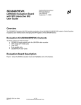
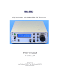
1
EEG-SMT development board USER’S MANUAL All boards produced by Olimex LTD are ROHS compliant Revision H, April 2013 Designed by OLIMEX Ltd, 2011 OLIMEX© 2012 EEG-SMT user's manual Disclaimer © 2013 Olimex Ltd. Olimex®, logo and combinations thereof, are registered trademarks of Olimex Ltd. Other product names may be trademarks of others and the rights belong to their respective owners. The information in this document is provided in connection with Olimex products. No license, express or implied or otherwise, to any intellectual property right is granted by this document or in connection with the sale of Olimex products. This work is licensed under the Creative Commons Attribution-ShareAlike 3.0 Unported License. To view a copy of this license, visit http://www.creativecommons.org/licenses/by-sa/3.0/. This hardware design by Olimex LTD is licensed under a Creative Commons Attribution-ShareAlike 3.0 Unported License. The software is released under GPL. It is possible that the pictures in this manual differ from the latest revision of the board. The product described in this document is subject to continuous development and improvements. All particulars of the product and its use contained in this document are given by OLIMEX in good faith. However all warranties implied or expressed including but not limited to implied warranties of merchantability or fitness for purpose are excluded. This document is intended only to assist the reader in the use of the product. OLIMEX Ltd. shall not be liable for any loss or damage arising from the use of any information in this document or any error or omission in such information or any incorrect use of the product. This evaluation board/kit is intended for use for engineering development, demonstration, or evaluation purposes only and is not considered by OLIMEX to be a finished end-product fit for general consumer use. Persons handling the product must have electronics training and observe good engineering practice standards. As such, the goods being provided are not intended to be complete in terms of required design-, marketing-, and/or manufacturing-related protective considerations, including product safety and environmental measures typically found in end products that incorporate such semiconductor components or circuit boards. Olimex currently deals with a variety of customers for products, and therefore our arrangement with the user is not exclusive. Olimex assumes no liability for applications assistance, customer product design, software performance, or infringement of patents or services described herein. THERE IS NO WARRANTY FOR THE DESIGN MATERIALS AND THE COMPONENTS USED TO CREATE EEG-SMT. THEY ARE CONSIDERED SUITABLE ONLY FOR EEG-SMT. Page 2 of 33 OLIMEX© 2012 EEG-SMT user's manual WARNING: EEG DEVICE DISCLAIMER IEC601 is a standard that specifies tests and requirements that medical devices must pass before they can be used on humans. However, none of the devices built from these designs have been tested according to these guidelines because of the costs involved. Therefore, a device based on any of these designs may not be used for medical purposes as no medical claims are made. Note that CONNECTING A DEVICE VIA ELECTRODES TO HUMANS OR ANIMALS IS POTENTIALLY HAZARDOUS AND MAY RESULT IN ELECTRIC SHOCK AND/OR SEIZURE. Finally, the authors do not guarantee that the information provided in the design files is complete or appropriate for any particular application. Full text at: http://openeeg.sourceforge.net/doc/WARNING.html. Page 3 of 33 OLIMEX© 2012 EEG-SMT user's manual Table of Contents Disclaimer.....................................................................................................................2 CHAPTER 1 | OVERVIEW....................................................................................... 5 1.1 Scope......................................................................................................................................... 5 1.2 Advantages of EEG-SMT........................................................................................................5 1.3 Organization.............................................................................................................................5 CHAPTER 2 | SETTING UP THE EEG-SMT BOARD..........................................7 2.1 Electrostatic Warning..............................................................................................................7 2.2 Requirements........................................................................................................................... 7 2.3 Powering up the board............................................................................................................8 2.4 How to setup the board, peripherals and your personal computer.................................... 8 CHAPTER 3 | IMPORTANT NOTES AND FAQ.................................................. 14 3.1 General notes regarding frequently encountered problems.............................................. 14 3.2 How to connect more than one EEG-SMT to a single PC..................................................17 CHAPTER 4 | EEG-SMT BOARD DESCRIPTION.............................................21 4.1 Outside layout........................................................................................................................ 21 4.2 Inside layout (top view):........................................................................................................21 4.3 Inside layout (bottom view):................................................................................................. 22 CHAPTER 5 | THE ATMEGA16 MICROCONTROLLER................................. 23 5.1 Processor features.................................................................................................................. 23 5.2 Processor memory map......................................................................................................... 25 CHAPTER 6 | POWER SUPPLY............................................................................ 26 6.1 Power supply.......................................................................................................................... 26 CHAPTER 7 | HARDWARE....................................................................................27 7.1 ICSP connector.......................................................................................................................27 7.2 V_CAL....................................................................................................................................27 7.3 USB connector........................................................................................................................28 CHAPTER 8 | SCHEMATIC................................................................................... 29 8.1 Eagle schematic......................................................................................................................29 8.2 Physical dimensions (without the case)................................................................................31 CHAPTER 9 | REVISION INFO AND USEFUL WEB LINKS........................... 32 9.1 Document revision................................................................................................................. 32 9.2 Web page of your device........................................................................................................32 9.3 Ordering info..........................................................................................................................33 Page 4 of 33 OLIMEX© 2012 EEG-SMT user's manual CHAPTER 1 | OVERVIEW Thank you for choosing the EEG-SMT bio-feedback board from Olimex! This document provides a User’s Guide for the Olimex EEG-SMT bio-feedback board. As an overview, this chapter gives the scope of this document and lists the board’s features. The document’s organization is then detailed. 1.1 Scope The EEG-SMT module is an inexpensive unit for electroencephalography (EEG) - recording of electrical activity along the scalp. The project is based on the efforts of the OpenEEG communty and our engineers here at Olimex. Project’s webpage can be found here: http://openeeg.sourceforge.net/ The OpenEEG project is about making plans and software for do-it-yourself EEG devices available for free (as in GPL). It is aimed toward amateurs who would like to experiment with EEG. EEG-SMT is based on the ModularEEG project. 1.2 Advantages of EEG-SMT Very low price compared to professional EEG devices Compact size Solid plastic case Powered by USB ICSP10 interface for reprogramming Fully open software and open hardware 1.3 Organization Each section in this document covers a separate topic, organized as follow: - Section 1 is an overview of the board usage and features - Section 2 provides a guide for quickly setting up the board and introduces the user to EEG-SMT prebuilt features - Section 3 contains the frequently asked question - Section 4 describes the component that is the heart of the board: the ATmega16 microcontroller and its memory map - Section 5 is an explanation of the control circuitry associated with the microcontroller to power - Section 6 details the power supply needed Page 5 of 33 OLIMEX© 2012 EEG-SMT user's manual - Section 7 covers the connector pinout and peripherals - Section 8 provides the schematics - Section 9 contains the revision history Page 6 of 33 OLIMEX© 2012 EEG-SMT user's manual CHAPTER 2 | SETTING UP THE EEG-SMT BOARD This section helps you set up the EEG-SMT development board for the first time. Please consider first the electrostatic warning to avoid damaging the board, then discover the hardware and software required to operate the board. The procedure to power up the board is given, and a description of the default board behavior is detailed. 2.1 Electrostatic Warning The EEG-SMT development board is shipped in a protective anti-static package. The board must not be exposed to high electrostatic potentials. A grounding strap or similar protective device should be worn when handling the board. Avoid touching the component pins or any other metallic element. 2.2 Requirements In order to set up the EEG-SMT evaluation board, the following items are required: EEG-SMT board itself EEG-AE - Active Electrode – 0 or 4 AE EEG-PE - Passive Electrode – 1 or 5 PE USB-CABLE – USB A to USB B cable 1.5 meter for EEG-SMT to connect to a computer VCP FTDI drivers (you can download the latest version from the official FTDI web site http://www.ftdichip.com/Drivers/VCP.htm) Electric Guru v0.40 monitoring software or latest BrainBay Note: You can either choose to use 5 passive electrodes or 4 active electrodes + 1 passive electrode (needed for electrical feedback). The EEG-SMT was designed to use standard passive EEG electrodes with shielded cables. However, when using active electrodes instead, no skin preparation is required and better performance can be achieved under imperfect conditions. The active electrodes described here connect directly to the EEG-SMT without requiring any modifications to the boards. Page 7 of 33 OLIMEX© 2012 EEG-SMT user's manual IMPORTANT NOTE: EEG-AEs, EEG-PEs, USB-CABLEs are sold separately and are NOT included in the box of EEGSMT Note: The board is not delivered with an ICSP debugger/programmer, which is needed if you don’t want to use its preprogrammed software (firmware). Remember that the connector on the board is ICSP (10 pin). You may use one of the following Olimex programmers for this purpose: -OLIMEX AVR-ISP-MK2 – 10pin ICSP and 6pin PDI, USB type A connection -OLIMEX AVR-ISP500-ISO – 10pin & 6pin isolated ICSP to USB type A -OLIMEX AVR-ISP500-TINY – 10pin & 6pin ICSP to USB type A -OLIMEX AVR-ISP500 – 10pin & 6pin ICSP to USB type A -OLIMEX AVR-PG1 – 10pin ICSP to RS232 -OLIMEX AVR-PG2 – 10pin ICSP to parallel port Also, a host-based software toolchain is required in order to program/debug the EEG-SMT board. 2.3 Powering up the board The EEG-SMT board is self-powered by the miniUSB port. Additionally the board can be powered using the 10pin ICSP connector. 20 seconds after powering the board PWR should go RED. The current consumption is around 0,8A. 2.4 How to setup the board, peripherals and your personal computer We have tested EEG-SMT with three software tools. These are the tools recommended by Olimex and explained below: Electric Guru; Brain Bay and OpenVibe. However, the board should work with any set of tools that supports OpenEEG/ModularEEG with firmware P2 (not P3). 1) Connect the EEG-SMT and a computer using the USB-CABLE 2) Go to device manager and locate the group “Other devices” and right click over the OLIMEX device. Chose update driver software. A dialog will appear and you click “Browse my computer for driver software” (the drivers can be downloaded from the FTDI web site under VCP link) 3) “Let me pick from a list of device drivers on my computer”->”Show all devices”-> Next 4) “Have disk”, and browse to the folder where you extracted CDM20814_WHQL_Certified.zip Page 8 of 33 OLIMEX© 2012 EEG-SMT user's manual and locate “ftdibus.inf” 5) Click Next and then “Install software anyway” 6) If you wish to use BrainBay skip to step 11); if you wish to use OpenVibe skip to step step 17); for Electric Guru continue reading: 7) Get the program from here: click to download 8) Extract the contents of the archive named “ElecGuru[vN].zip” and run the executable It is advisable to make the changes shown in the picture below in your ElecGuru program in preferences-> Trace (waveform); also make sure you have selected the proper COM port 9) Connect the 5 electrodes to the EEG-SMT (!!! The one connected to DLR must be passive electrode) 10) Place the DLR electrode (feedback) on your ear and the other 4 on your head depending what kind of brain activity you want to monitor – there is diagram on the next page showing the spots you might use. For example if you want to monitor the Frontal Lobe (thought processing) you place the electrodes on Fp1, Fp2, F7, F8 spots (and DLR electrode to one of the ears A1, A2). Page 9 of 33 OLIMEX© 2012 EEG-SMT user's manual If you want to monitor visual perception you have to monitor the Occipital Lobe – Fp1, Fp2, O1 and O2. For more information on the functions of the brain and the respective brain zones refer to the Wikipedia article: http://en.wikipedia.org/wiki/Brain#Functions 11) Download Brainbay software from their official web site: http://www.shifz.org/brainbay/ 12) Install the program and run it 13) Click Load Design and import a sample project from folder Test_Elements (for example modeeg_test.con or 2chn_test.con, but feel free to check others also) 14) From Option -> Device manager change the COM port to the COM port EEG-SMT is assigned to and the baud rate to 57600 (you can check/change the COM in Windows Device Manager in Ports section, the device is recognized as USB Serial port (COM X)) 15) Do steps 9) and 10) 16) Click Play (F7) Page 10 of 33 OLIMEX© 2012 EEG-SMT user's manual 17) Visit OpenVibe's web page: http://openvibe.inria.fr/ and download the installation from the download button. 18) Install OpenVibe and from the start menu navigate to the start menu folder that the installer created. Run “openvibe acquisition server”. 19) Select “OpenEEG Modular EEG p2” from the drop-down menu and adjust it's properties. Especially change the COM port to the proper port the EEG-SMT got connected to (after the drivers were installed in point 6) and also remember to reduce the number of channels to 1 or 2! 20) Click Connect and then click Run 21) Run the OpenVibe client designer from the start menu shortcut “openvibe designer” 22) Create new design from File - > New 23) In the search box (to the right in the interface): type “acquisition” and drag-and-drop Acquisition client to the design workspace (to the left in the interface) 24) In the search box (to the right in the interface): type “display” and drag-and-drop the Signal Display box the design workspace (to the left in the interface) 25) Connect the two elements as shown in the picture below: Page 11 of 33 OLIMEX© 2012 EEG-SMT user's manual 26) Do steps 9) and 10) 27) Click “Play” from the tool bar at the top of the Designer interface Below is an example one-channel operation of OpenVibe: Page 12 of 33 OLIMEX© 2012 EEG-SMT user's manual More information on the OpenVibe setup may be found at their web page. The basic setup design is described here: “http://openvibe.inria.fr/tutorial-the-most-basic-openvibe-setup/”. Page 13 of 33 OLIMEX© 2012 EEG-SMT user's manual CHAPTER 3 | IMPORTANT NOTES AND FAQ 3.1 General notes regarding frequently encountered problems - The virtual com port must be numbered 1, 2, 3 or 4 in order to use ElecGuru, which you can do in Device Manager. Right-click over the COM port the device was installed onto and click “Properties”, then navigate to “Port Settings”, then to “Advanced” and finally change “COM number”. Check the screenshot below: - The COM port which ElecGuru uses can be changed from preferences-> serial port. - You have to install the drivers then start the ElecGuru program AND THEN connect the electrodes. - If using only ONE channel it is recommended to short circuit the other channel, or connect it to the DLR for less noise - Feel free to try other software that supports OpenEEG ModularEEG firmware 2 (P2) data packing. - If you wish to change the update rate of the graph (e.g. make it update data on little intervals so the line seems fluid – more sensitive to changes) you have to change the Latency Timer of the virtual COM port. It is done from the same menu where you can change your COM number. Page 14 of 33 OLIMEX© 2012 EEG-SMT user's manual Change it to 1ms or 2ms delay. Check the screenshot below: There are reports that on certain operating systems it is possible that after installing the drivers and connecting the device the mouse pointer would become unresponsive and would act crazy. It is a bug we have reported to Microsoft and FTDI. This bug persists in the COM communication since Windows 2000. There are two solutions available: 1)The first solution: Go to the device manager before plugging the device and mark an entry there. Then plug the EEG-SMT to the computer (and your mouse will go crazy!) leave the mouse and use the keyboard arrows and TAB to navigate in the device manager and reach the MICROSOFT SERIAL BALLPOINT DEVICE and press Enter on it. Then when General tab is marked (with dotted rectangle) press Right keyboard arrow which will lead you to Driver tab and using keyboard button TAB navigate to disable and hit enter. Check the following screenshot: Page 15 of 33 OLIMEX© 2012 EEG-SMT user's manual 2)The second solution (Please follow carefully and at own risk): a solution that worked for me was to go into the registry (Start → Run/Search → “regedit” → Enter) and edit the following value: Location: HKEY_LOCAL_MACHINE\System\CurrentControlSet\Services\sermouse Key: Start Default value: 3 Page 16 of 33 OLIMEX© 2012 EEG-SMT user's manual Modify Value to 4, which is Disabled and it will stop this problem occurring. Check the pictur e below: More info on the software which the board was tested with can be found here: http://www.shifz.org/brainbay/ Here you get acquainted with the main parts of the board. Note the names used on the board might differ from the names used to describe them. For the actual names check the EEG-SMT board itself. 3.2 How to connect more than one EEG-SMT to a single PC A lot of customers have asked for a way of using more than two channels with our EEG-SMT. The design doesn't allow easy hardware modification to achieve that so the only way is by software means. Now this is problematic since if you plug more than one EEG-SMT they get recognized as the same device. Furthermore, all EEG software we tested (Electric Guru, Brain Bay, Open ViBE) lacked support for two (or more) inputs, e.g. two (or more) EEG-SMTs plugged simultaneously. The good news is that it is actually possible to have more than one EEG-SMT on a computer station BUT you need to use two (or more) instances of the same software (for example you have to run Brain Bay two times). In one of the instances you will see data coming from the first of the EEG-SMTs, in the other you will see the second of the EEG-SMTs. To continue with the good news to configure the devices in such a way you don’t need additional hardware, nor you need to open them. It can be done via the USB. The steps to do so are listed below: Important! Modifying other values than the ones suggested below might cause serious troubles and even render the EEG-SMT unrecoverable. 1. Connect EEG-SMT to a computer via the USB (and ensure no other FTDI devices are connected to the computer) 2. Make sure the drivers of the device are installed (if not install them from http://www.ftdichip.com/Drivers/VCP.htm) 3. Download and extract the FT_PROG utility from FTDI’s web site: http://www.ftdichip.com/Support/Utilities.htm. 4. Run FT_prog.exe and select "Scan and Parse” from the menu Page 17 of 33 OLIMEX© 2012 EEG-SMT user's manual 5. In the left panel navigate to “USB String Descriptors” and then in the right one make sure the “Serial Number” is enabled and the “Auto Generate Serial No” is enabled also. Page 18 of 33 OLIMEX© 2012 EEG-SMT user's manual 6. Right-click over Device 0 and choose to program device Page 19 of 33 OLIMEX© 2012 EEG-SMT user's manual 7. Close FT_prog and power cycle the EEG-SMT, then connect the second EEG-SMT 8. Open “Windows Device Manager” and if both devices are enumerated with the same COM port # change one of them to another COM port # (from Properties –> Port Settings –> Advanced –> COM port number) 9. Start two instances of a supported program (or two different supported programs). In their options set one to the COM port # of EEG-SMT#1 and the other to the COM port # of EEG-SMT#2 Note: This way you can configure more than 2 EEG-SMT devices (4 channels) as long as your USB hub (computer motherboard, power supply, etc.) is able to power the number of EEG-SMT devices connected. Page 20 of 33 OLIMEX© 2012 EEG-SMT user's manual CHAPTER 4 | EEG-SMT BOARD DESCRIPTION 4.1 Outside layout 4.2 Inside layout (top view): Page 21 of 33 OLIMEX© 2012 EEG-SMT user's manual 4.3 Inside layout (bottom view): Page 22 of 33 OLIMEX© 2012 EEG-SMT user's manual CHAPTER 5 | THE ATMEGA16 MICROCONTROLLER 5.1 Processor features • High-performance, Low-power Atmel® AVR® 8-bit Microcontroller • Advanced RISC Architecture – 131 Powerful Instructions – Most Single-clock Cycle Execution – 32 x 8 General Purpose Working Registers – Fully Static Operation – Up to 16 MIPS Throughput at 16 MHz – On-chip 2-cycle Multiplier • High Endurance Non-volatile Memory segments – 16 Kbytes of In-System Self-programmable Flash program memory – 512 Bytes EEPROM – 1 Kbyte Internal SRAM – Write/Erase Cycles: 10,000 Flash/100,000 EEPROM – Data retention: 20 years at 85°C/100 years at 25°C – Optional Boot Code Section with Independent Lock Bits In-System Programming by On-chip Boot Program True Read-While-Write Operation – Programming Lock for Software Security • JTAG (IEEE std. 1149.1 Compliant) Interface – Boundary-scan Capabilities According to the JTAG Standard – Extensive On-chip Debug Support – Programming of Flash, EEPROM, Fuses, and Lock Bits through the JTAG Interface • Peripheral Features – Two 8-bit Timer/Counters with Separate Prescalers and Compare Modes – One 16-bit Timer/Counter with Separate Prescaler, Compare Mode, and Capture Mode – Real Time Counter with Separate Oscillator – Four PWM Channels – 8-channel, 10-bit ADC 8 Single-ended Channels 7 Differential Channels in TQFP Package Only 2 Differential Channels with Programmable Gain at 1x, 10x, or 200x – Byte-oriented Two-wire Serial Interface – Programmable Serial USART – Master/Slave SPI Serial Interface Page 23 of 33 OLIMEX© 2012 EEG-SMT user's manual – Programmable Watchdog Timer with Separate On-chip Oscillator – On-chip Analog Comparator • Special Microcontroller Features – Power-on Reset and Programmable Brown-out Detection – Internal Calibrated RC Oscillator – External and Internal Interrupt Sources – Six Sleep Modes: Idle, ADC Noise Reduction, Power-save, Power-down, Standby and Extended Standby • I/O and Packages – 32 Programmable I/O Lines – 40-pin PDIP, 44-lead TQFP, and 44-pad QFN/MLF • Operating Voltages – 2.7V - 5.5V for ATmega16L – 4.5V - 5.5V for ATmega16 • Speed Grades – 0 - 8 MHz for ATmega16L – 0 - 16 MHz for ATmega16 • Power Consumption @ 1 MHz, 3V, and 25°C for ATmega16L – Active: 1.1 mA – Idle Mode: 0.35 mA – Power-down Mode: < 1 μA For comprehensive information on the microcontroller visit the ATMEL’s web page for a datasheet. At the moment of writing the microcontroller’s datasheet can be found at the following link: http://www.atmel.com/dyn/resources/prod_documents/doc2466.pdf Page 24 of 33 OLIMEX© 2012 EEG-SMT user's manual 5.2 Processor memory map Page 25 of 33 OLIMEX© 2012 EEG-SMT user's manual CHAPTER 6 | POWER SUPPLY 6.1 Power supply When EEG-SMT is connected via a USB cable to a USB host it will take its 5V power supply from the USB host source to power the board. Additionally the board can be powered using the 10pin ICSP connector. When powered and functional the current consumption is around 80 mA. Page 26 of 33 OLIMEX© 2012 EEG-SMT user's manual CHAPTER 7 | HARDWARE The hardware section for EEG-SMT includes description of the connectors and the jumpers. 7.1 ICSP connector The 10 PIN ICSP connector provides option to reprogram the board if you want to use it as a general development board. Pin # Signal Name 1 MOSI 2 +5 VD VCC 3 Not connected 4 Digital GND 5 RST 6 Digital GND 7 SCK 8 Digital GND 9 MISO 10 Digital GND 7.2 V_CAL V_CAL is interface used for the calibration of the instrumentation amplifier INA114BU/1K. You will need to make own connector in order to calibrate it. Pin # Signal Name 1 V_CAL 2 GND Page 27 of 33 OLIMEX© 2012 EEG-SMT user's manual 7.3 USB connector Pin # Signal Name 1 +5V_VBUS 2 USBDM 3 USBDP 4 GND/SHIELD Page 28 of 33 OLIMEX© 2012 EEG-SMT user's manual CHAPTER 8 | SCHEMATIC 8.1 Eagle schematic The EEG-SMT schematic is situated on the next page for quicker reference. You can also download it as a stand-alone .pdf with better quality check the web page of EEG-SMT (located in the hardware section): https://www.olimex.com/Products/EEG/OpenEEG/EEG-SMT/ Page 29 of 33 OLIMEX© 2012 EEG-SMT user's manual 10k/1% 0R C73 R15 USB 0R 0R 0R(NA) 2 3 L1 R63 C22 1M C21 NA 10nF/X7R/10% C20 NA GND AGND C23 17 3V3OUT 100nF/X 7R/10% NA(USBLC6-2P6) 6 5 4 FB /60 0 OH M /1 2 0 6 (3 2 1 6 1 1 C -6 0 1 ) 0R(NA) 1 R14 C19 + C18 R62 560R SHIELD 10uF/6.3V/TANT R52 0R(NA) PWR 3mm_Red USB 1 2 3 4 USB_B 8 19 24 27 28 NC1 #RESET NC2 OSCI OSCO NA BZV55C6V2 FT232RL CBUS0 CBUS1 CBUS2 CBUS3 CBUS4 22µH/± 10%/1. 7ohm/80mA(LB2012T 220K/8030984) 16 15 R13 + + Z1 23 22 13 14 12 4 20 USBDM USBDP GND Isolation VIN L2 U4 VCCIO VCC 100nF/X7R/10% PD5 FT232RL/SSOP28 2.2k/1% R53 NA(10M ) V_REF 100R R54 NA (10M ) +5VA C38 10nF/X7R/10% R60 +5VA R28 PGS4 100R CH2_IN+ 2.2k/1% SCJ325P 00XG0B02G PGB1010603MR(F25 94 TR-ND) DRL +5VA R61 NA DRL PGS5 2 R56 PGB1010603 MR(F2 594T R-ND) D5 2.2k/1% BAV199(1156415) 5 7 R33 R29 R30 +5VA 4 2.2k/1% 2 R31 2.2k/1% 15 R32 2.2k/1% 5 3 2 V_REF 25k RG 25k 100nF/X7R/10% RG 25k V+IN 1k C53 10k/1% 15k/1% 5 10 REF 25k 13 V+ 7 V- 25k 1 TR3 2 VREF AGND 1 Close 1 NA(20k)??? 2 R39 100nF/X7R/10% R37 1M/1% 100nF/X7R/10% 100nF/X7R/10% IC2A MCP607-I/SN 1 1uF/X5R/10% C49 C48 V_REF V_REF C69 TR3_DIS 5 V_REF 3 TR2 20k 1 3 1 R41 C54 C58 C56 1uF/X5R/10% 100k/1% R43 1M/1% 1nF/X7R/10% R45 R47 10k/1% 15k/1% V_REF 100nF/X7R/10% 100nF/X7R/10% 100k/1% C61 100nF/X7R/10% C65 1nF/X7R/10% 100nF/X7R/10% V_REF 220nF /X7R/5%(08053C224JAT 2A/ 1740667) V_REF If TR3 is needed, adjust potentiometer so DRL=0mV (referred to V_REF) when _all_ amplifier inputs are shorted to the DRL output (R_LEG). Important usage instructions for the DRL. If you only want to use one channel, never let the other channel float. Always connect the unused terminals to V_REF, or the DRL will not work properly. V_REF DRL design from http://www.biosemi.com/publications/artikel7.htm, fig.3 Page 30 of 33 V_REF IC2B MCP607-I/SN 5 7 100nF/X7R/10% 6 C66 R51 R49 8.2k/1% V_REF C67 33nF/X7R/5%(06 035 C3 33JAT 2A/1 740618) C60 1k Right-leg driver (DRL) notes: 100nF/X7R/10% C71 C63 R50 R48 V_REF +5VA C70 7 V_REF 3 C50 10k/1% COM 7 6 C59 220nF /X7R/5%(08053C224JAT 2A/ 1740667) C64 100nF/X7R/10% 8 R46 8.2k/1% C52 R34 6 3 1 3 11 VO 1nF/X7R/10% 3 R40 1uF/X5R/10% 100k/1% R42 1M/1% 1nF/X7R/10% R44 IC1B MCP607-I/SN +5VA 12 FB 25k MCP607-I/SN 200k/1% C44 1nF/X7R/10% 3 TR1 20k 1 C55 33nF/X7R/5%(06 035 C3 33JAT 2A/1 740618) +5VA INA114BU/1K V-IN IC3A BAV199(1156415) R36 1M/1% 100nF/X7R/10% C47 2 R38 100nF/X7R/10% C57 IC1A MCP607-I/SN 1 1uF/X5R/10% C46 C45 V_REF V_REF 2.2k/1% D4 IC4B TLC277CD 13 V+ 7 V- 25k 3 10 REF 25k G= 13 10k/1% BAV199(1156415) C43 R35 25k V+IN 11 VO U6 NA(10M) SCJ325P 00XG0B02G RG IC3B 1 R55 25k C51 MCP607-I/SN D3 V_REF RG The 3rd pole is located on the digital part. Fc=0.16Hz +5VA 12 FB 25k 8 1-L SCJ325P 00XG0B02G R27 2.2k/1% C42 R59 5 +5VA 100pF/COG/5% 2 15 2.2k/1% 6 C41 CH2_IN3-R 2.2k/1% R26 BAV199(1156415) 100pF/COG/5% PGS3 CH2_IN- R25 D2 SCJ325P 00XG0B02G PGB1010603MR(F25 94 TR-ND) PGB1010603MR(F25 94 TR-ND) 2 25k 3rd order "Besselworth" filter, fc = 59 Hz. 4 +5VA 2.2k/1% V-IN 2 R24 4 1 pole 8 R22 PGS2 100R CH1_IN+ 2.2k/1% High-Pass filter 100k/1% C62 100nF/X7R/10% 4 +5VA R23 BAV199(1156415) Non-Inverter Amplifier G=11..101 G=40 +5VA INA114BU/1K NC NC NC NC NC NC NC R58 U5 1 3 6 8 9 14 16 C37 10nF/X7R/10% Fc=0.16Hz NC NC NC NC NC NC NC +5VA 1 pole 1 3 6 8 9 14 16 100R CH1_IN+ 1-L High-Pass filter +5VA 2 1-L SCJ325P 00XG0B02G 2.2k/1% C40 R57 R21 100pF/COG/5% 2 3-R +5VD 22µH/± 10%/1.7ohm/80mA(LB2012T220K/ 8030984) Instrumental Amplifier G=12.36 D1 NA(10M) C39 CH1_IN3-R 1-L 3 4 L3 PD5 V_REF R8 100pF/COG/5% PGS1 CH1_IN- 3-R +5VA 2 High Voltage protection PGB1010603MR(F25 94 TR-ND) CH2_IN+ 1-L 2 INB GND1 ISO7221XD(SOIC8) PD5 is PWM output for cal-signal V_REF 3-R OUTB GND2 VCC1 OUTA 10k/1% HF rejection 2 VCC2 INA TXD RXD RTS# CTS# DTR# DSR# DCD# RI# 250µVpp +/-10%, 0.1 .. 100Hz Square wave Calibration Signal R18 GND_CAL 6 5 TDI TDO TMS TCK ATMEGA16 R20 1M/1% 1M/1% voltage divider 1:20000 5Vp-p +/-10% => 250µVp-p +/-10% R17 100R/1% 220nF /X7R/5%(08053C224JAT 2A/1740667) 220nF /X7R/5%(08053C224JAT 2A/1740667) 1 5 3 11 2 9 10 6 1 2 100nF/X 7R/10% R19 8 7 1k 100nF/X7R/10% U3 7 25 R16 4 V_CAL PWREN C16 C13 100nF/X7R/10% TEST GND GND2 47µF/10%/6.3V/TANT(C)/ESR 0.25 ohm (TR3C476K6R3C0250/1754044) 7.5k/1% 7.5k/1% R12 10k R11 18 GND1 39 0V 26 21 18 R9 R10 C9 C10 16 15 14 13 12 11 10 9 (OC2)PD7 (ICP)PD6 (OC1A)PD5 (OC1B)PD4 (INT1)PD3 (INT0)PD2 (TXD)PD1 (RXD)PD0 GND TMV0505S C17 100nF/X7R/10% 100nF/X 7R/10% +5VD C24 6 10uF/6.3V/T ANT 2 VIN- 10nF/X7R/10% 100 nF/X 7R/10% VOUT- 100nF/X7R/10% U7 C15 DC-DC converter 5 10uF/6.3V /T A NT ADC1 ADC0 C14 C26 V_REF VCC2 C7 C72 100nF/X7R/10% 8 4 10nF/X7R/10% 47µF/6.3V/TANT 10nF/X7R/10% C32 + 38 C8 C31 100nF/X7R/10% VIN+ FET IRLML6402 +5V_USB 1 C25 2V_REF_BUF TLC277CD VCC1 +5V VOUT+ C12 HN2x5 26 25 24 23 22 21 20 19 (TOSC2)PC7 (TOSC1)PC6 PC5(TDI) PC4(TDO) PC3(TMS) PC2(TCK) PC1(SDA) PC0(SCL) VCC 17 IC4A 100nF/X7R/10% + C35 100nF/X7R/10% C36 C34 C33 5 1 100nF/X7R/10% AGND +5VD C30 2 AVCC 28 ISOLATED PART U2 7 + 27 VIN C11 3 2 1 44 43 42 41 40 (SCK)PB7 (MISO)PB6 (MOSI)PB5 (SS)PB4 (AIN1)PB3 (AIN0/INT2)PB2 (T1)PB1 (T0)PB0 AREF +5VD 100nF/X7R/10% 29 +5VA 3 XTAL1 2 4 6 8 10 47µF/6.3V/TANT AP431SA 8 7.3728M Hz/2 0pF/30ppm 10nF/X7R/10% A Q1 39pF/COG/5% XTAL2 RST SCK MISO C27 7 (ADC7)PA7 (ADC6)PA6 (ADC5)PA5 (ADC4)PA4 (ADC3)PA3 (ADC2)PA2 (ADC1)PA1 (ADC0)PA0 3 5 7 9 10nF/X 7R/10% 39pF/COG/5% 30 31 32 33 34 35 36 37 C29 C2 ICSP MOSI 1 RESET + 4 C4 100nF/X7R/10% R R5 15k/1% 100nF/X7R/10% C3 C5 C 10uF/6.3V/TANT R7 10k/1% SR1 R4 9.1k/1% + C6 C1 C28 R2 100R 4V_REF_ADC R6 10k/1% RST U1 R3 560R 2V_REF RST 100nF/X7R/10% +5VD +5VA 10k 47µF/6.3V/TANT R1 C68 1nF/X7R/10% 100nF/X7R/10% V_REF EEG-SMT_rev_B OLIMEX LTD, BULGARIA https://www.olimex.com OLIMEX© 2012 EEG-SMT user's manual 8.2 Physical dimensions (without the case) The board is shipped in a protective PVC case. These are the bare board dimensions. Note: All measurements are in INCHES. Page 31 of 33 OLIMEX© 2012 EEG-SMT user's manual CHAPTER 9 | REVISION INFO AND USEFUL WEB LINKS 9.1 Document revision Revision Changes Modified Pages A Initial Creation All B Added additional info on changing COM port number and added info on how to resolve a conflict with the mouse 10.11 C Added info on how to change the latency timer so you can receive responses more often 11.12 D Added new solution to the serial mouse problem 12 E Updated the name of the device in the document, updated links All F Changed the template formatting of the document, added info about OpenVibe, changed schematic with All a searchable one, fixed various errors and mistakes G Added new section, how to run more than one EEG17 SMT on the same computer H Changed disclaimer to fit properly the open hardware tag of the board 2 9.2 Web page of your device The web page you can visit for more info on your device is https://www.olimex.com/Products/EEG/OpenEEG/EEG-SMT/. There you can find more info and some examples. Page 32 of 33 OLIMEX© 2012 EEG-SMT user's manual 9.3 Ordering info ORDER CODES: EEG-SMT - assembled, programmed, tested, calibrated EEG device EEG-AE - active electrode EEG-PE - passive electrode USB-CABLE - USB A to B cable 1.5 meter for EEG-SMT How to order? You can order from our web shop or from any of our distributors. List of distributors: https://www.olimex.com/Distributors Check our web site https://www.olimex.com/ for more info. Page 33 of 33