1
TM
Automate Test Design™
User Manual
Conformiq Qtronic2 Manual
Copyright (C) Conformiq Software Ltd and its subsidiaries 1998-2008. All Rights Reserved. All information may be
subject to change without notice.
For more information about Conformiq Software and its products, please go to http://www.conformiq.com/.
Conformiq, Conformiq Qtronic and Conformiq Modeler are trademarks of Conformiq Software Ltd. Java is a
trademark of Sun Microsystems. UML is a trademark of the Object Management Group. Other trademarks
appearing in the text belong to their respective owners.
iii
Table of Contents
1
Introduction
1.1
1.2
1.3
1.4
The Design-Validation Cycle
Costs of Testing
Conformiq Qtronic in Software Process
Benefits of Conformiq Qtronic
9
10
12
14
2
Installing Conformiq Qtronic2
16
2.1
System Requirements
Qtronic Eclipse Client Requirements
Qtronic Computation Server Requirements
Other Requirements
Preparations
Installing Qtronic 2 on Windows
How to Install Qtronic 2 on Windows
How to Uninstall Qtronic 2 on Windows
Installing Qtronic 2 on Linux
How to Install Qtronic 2 on Linux
How to Uninstall Qtronic 2 on Linux
Checking the QEC Installation
License Management in Qtronic2
Configuring Qtronic Feature Set
Qtronic Evaluation
Node-Locked Licensing
Floating Licensing
Obtaining Node Identifiers
License Server Management
Viewing Licensing Status
Adding Licenses
17
17
17
18
18
19
19
20
21
21
22
23
25
26
27
29
29
30
31
32
33
2.1.1
2.1.2
2.1.3
2.2
2.3
2.3.1
2.3.2
2.4
2.4.1
2.4.2
2.5
2.6
2.6.1
2.6.2
2.6.3
2.6.4
2.6.5
2.7
2.7.1
2.7.2
8
iv
Qtronic2 Manual
3
Testing with Conformiq Qtronic2
3.1
3.2
3.3
3.4
3.5
3.6
3.7
34
Quick Start of Using Qtronic 2
How to Switch to Qtronic Perspective
How to Configure Qtronic2 Client
How to Work with Qtronic2 Projects
How to Select Models
How to Create Test Design Configurations
How to Configure Test Generation
3.7.1
How to Configure Global Testing Parameters
3.7.2
How to Configure Design Configuration Specific Testing Parameters
3.8
How to Generate Tests
3.9
How to Analyze Test Generation Results
3.9.1
Coverage Editor
3.9.2
Test Case List
3.9.3
Traceability Matrix View
3.9.4
Test Case View
3.9.5
Test Step View
3.9.6
Execution Trace View
3.9.7
Analyzing Model Defects
3.10
How to Export Test Cases
3.10.1
How to Use Script Backends Shipped with Qtronic2
3.11
Test Case Management
3.12
Managing Qtronic Projects
36
37
38
39
42
44
46
46
49
55
57
58
59
61
62
64
66
66
68
71
76
79
4
Creating Models in QML
81
4.1
4.2
Textual Notation of QML
Basic Language Features
Keywords
Comments
Literals
Operators
82
84
84
88
88
88
4.2.1
4.2.2
4.2.3
4.2.4
v
4.2.5
4.2.6
4.2.7
4.2.8
4.2.9
4.2.10
4.2.11
4.2.12
4.2.13
4.2.14
4.3
4.3.1
4.3.2
4.3.3
4.3.4
4.3.5
4.3.6
4.4
4.4.1
4.5
4.5.1
4.5.2
4.5.3
4.5.4
4.5.5
4.6
4.6.1
4.6.2
4.6.3
4.6.4
4.6.5
Data Types
Access Modifiers
Type Aliases
Control structures
Input and Output
System Block
Main Entry Point
Globals and Functions
Modifiers
Regions with No Coverage Goals
Object Orientation
Inheritance
Interfaces
Operator Overloading
Templates
Nullable Types
Implicitly Typed Local Variables
Modeling Use Cases with QML
An Example
Predefined Data Types
Class and Record Super Types
Threads and Communication
Exceptions
Synchronization
Containers
Predefined Functions
Assertion Like Functions
Requirements
Random Number Generators
Mathematical Functions
Use Cases
90
99
100
100
102
104
104
105
105
105
106
106
107
107
108
110
111
113
114
116
116
117
120
121
122
126
126
128
129
130
130
vi
Qtronic2 Manual
4.6.6
4.6.7
4.6.8
Probabilities and Priorities
End Conditions for Test Generation
Miscellaneous Functions
4.7
Backward Compatibility with Conformiq Test Generator
4.7.1
Optional Fields in Records
4.7.2
Type Copies
4.8
Graphical Notation of QML
4.8.1
State Machines
4.8.2
Transition Strings
4.8.3
Internal Transitions of a State
4.9
Importing QML Models Into Qtronic
4.10
Examples
4.10.1
A Simple Echo Model
4.10.2
Another Echo Model
4.10.3
Yet Another Echo Model
131
134
135
136
136
137
138
138
139
143
144
145
145
146
147
5
Using Conformiq Modeler
150
5.1
5.2
5.3
5.4
5.5
Opening a model
Saving a model
State machines
Drawing
Zooming
Scrolling
States
Transitions
Notes and note connectors
Undo and Redo
153
153
153
153
154
154
154
155
155
156
6
Importing Models from Third Party Tools
5.4.1
5.4.2
5.4.3
5.4.4
5.4.5
6.1
Enterprise Architect
6.1.1
Imported Components
157
158
158
vii
6.1.2
A Simple Example
7
Creating Qtronic2 Scripting Backends
7.1
7.2
7.3
7.4
7.5
7.6
7.7
Communicating Using QML Datum Interface
Creating Scripting Backends in Java
Exposing Scripting Backend Configuration
Preparing Eclipse Workbench
Creating Java Project for Scripting Backends
Creating Scripting Backend JAR
Debugging Scripting Backends
8
Support and Troubleshooting
8.1
8.2
Troubleshooting Guidelines
8.1.1
Troubleshooting QEC
8.1.2
Performance Problems
Reporting Problems with Qtronic
A
Qtronic 2 Release Notes
A.1
A.2
A.3
A.4
A.5
Download and Install
Qtronic 2.0.3
Qtronic 2.0.2
Qtronic 2.0.1
Qtronic 2.0.0
B
Plugin API Reference Manual
159
163
164
165
169
172
172
174
174
176
177
177
178
178
180
181
182
183
183
183
186
1 Introduction
Introduction
9
Welcome to use Conformiq Qtronic, the world's leading solution for automatic model
driven test case design!
Conformiq Qtronic is the result of more than five years of continuous programming and
development. It is based on advanced discrete mathematics and theory of computer science,
yet it is a very pragmatic tool. The benefits that Conformiq Qtronic brings into day-to-day
software development are tangible and pervasive. It reduces risks caused by accidentally
missing tests or defective tests and increases test design productivity and target system
quality.
In this introduction we go through the value proposition for Conformiq Qtronic: what it is,
why it exists, and how it can help you.
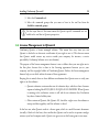
1.1 The Design-Validation Cycle
On high level, software development can be seen to consist of interleaved cycles of design and
validation. Design is about creating business requirements and architectural plans, writing
running code, producing implementations. Validation is about checking what has already
been designed with respect to other explicit artifacts as well as implicit requirements in the
process.
10
Qtronic2 Manual
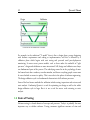
Overview of the traditional V model
For example, in the traditional "V model" there is first a design phase, process beginning
with business requirements and ending at implementation, and this is followed by a
validation phase which begins with unit testing and proceeds until post-deployment
monitoring. In more recent process models, such as those under the umbrella of "agile
processes", design and validation are more intertwined. Still, design and validation are always
two fundamental parts of the process. The underlying reason lies in the psychology of man:
the human brain has a tendency to make mistakes, and hence everything people create must
be cross-checked to ensure its quality. This is true also in the sphere of software engineering.
The design-validation cycle is a fundamental characteristic of all software processes.
Some of the best known methods for validation include testing, inspections and reviews, and
static analysis. Conformiq Qtronic is a tool for optimizing test design as well as the whole
design-validation cycle in large. But it is not a tool for source code reviewing or static
analysis.
1.2 Costs of Testing
Software testing is a broad domain of concepts and processes. Today it is probably the most
important way to validate software. Testing consumes significant amounts of time and
Introduction
11
money, estimated from 30 to 90 percentages out of total development budgets.
The division of testing costs depends on how testing is organized. Typical ways to organize
testing include:
• Manual testing
• Record and replay
• Development and execution of custom testing software
Manual testing means that a testing engineer or tester interacts with the system under test
personally, often following a plan written down in a human tongue, creating reports of his or
her experiences with the system as well as of any defects spotted. The dominating costs are
personnel costs caused directly by the testing activity on hour to hour basis.
Record and replay is a widely deployed paradigm for testing software with graphical user
interfaces. First, a tester interacts manually with the system under test through the user
interface. The interaction is recorded in a suitable way. Later the interaction can be replayed
many times and the workings of the system compared to the expected, "golden" outcomes
that come either from the original execution or from an otherwise prepared data table. In
record and replay the costs are attributed to the production of the scripts in the first place,
the maintenance and modification of them later when the product or its requirements
change during the life cycle, the examination of those cases where tests fail for diagnosis, and
the total cost of the ownership of the record and replay tool itself.
Record and replay excels in a process where progressive versions of the same software must be
tested many times (regression testing). Record and replay achieves relative economics of scale
over manual testing when the number of regression test runs grows.
The same is true for using custom testing software. This is a typical way to organize regression
tests for small units, but it is used also for larger systems. In this approach, a testing engineer
creates and maintains custom software whose raison d'être is to, when executed, test some
other software. The initial development costs for custom testing software can be higher than
for record and replay — at least a different skill set is required — but in the long run it can
be more efficient. Typically, a custom testing program can generate millions of different test
12
Qtronic2 Manual
inputs to a system, and can analyze the outcome from the system in a much more detailed
way than a usual record and replay solution.
Because testing is eventually cross-checking an implementation against requirements, all
forms of testing create costs related to understanding and analyzing requirements. In the
context of manual testing these costs show up as working time spent by testers during the
testing activity itself. For custom testing software, both test design as well as analysis of
flagged defects incur costs (all automatically spotted defects must be analyzed because it
could be that the testing software itself, being just another computer program written by a
human, could be incorrect in itself).
For our purposes, a coarse but sufficient way to categorize the cost drivers of a testing process
is:
1. Understanding and analyzing requirements
2. Creating and maintaining test artifacts (recorded interactions, custom testing
software)
3. Executing tests (either manually or by running automation tools)
4. Analyzing test results
5. Reporting
1.3 Conformiq Qtronic in Software Process
Conformiq Qtronic is a tool for automatic test case design that is driven by "design models".
This means that Conformiq Qtronic designs tests for a system automatically when it is given
a "design model" of the system as an input. The tests are "black box tests", meaning that they
evaluate the system under test based only on its external behavior, not on monitoring its
internal workings directly (this kind of testing would is called "white box testing").
This "design model" is a description of the intended behavior of the system on some level of
abstraction. It is also correct to see it as a golden reference implementation of the system,
albeit usually an abstracted and simplified one. This design model can be expressed as a
Introduction
13
collection of
1. Textual source files in Java-compatible but extended notation that describe data
types, constants, classes and their methods (the extensions include support for
value-type records, true static polymorphism, etc.).
2. Statechart diagrams with methods and procedures in Java syntax representing the
behavioral logic of active classes, i.e. classes whose instances can “execute on their
own” as an alternative to representing the logic textually.
3. Class diagrams as a graphical alternative to declare classes and their relationships.
Design models can also be seen as operational requirements or behavioral requirements. They
describe the intended external operational characteristics of the system, in essence how the
system should work from the perspective of a user. Design models do not need to reflect the
real implementation structurally as long as they describe the intended outwardly observable
characteristics.
Conformiq Qtronic selects and optionally executes tests automatically based on the design
model, and calculates expected answers from the system under test automatically. With
Conformiq Qtronic, there is no need to create test scripts manually or to record them. Test
design, optional execution and analysis are all automatic. These benefits directly reduce costs
and risks. But behind this level of "obvious" benefits, Conformiq Qtronic brings in a
pervasive change to the software process: it links design with validation in a revolutionary
way.
Without Conformiq Qtronic, testing involves manual translation of requirements into tests
and test verdicts. This task is carried out either by a manual tester, a test designer, or an
engineer writing testing software — in the last case the costs are the most directly visible.
Basically, a custom testing program is just a new expression of the requirements for the
system, this time in the form of an executable that checks that the system the executable is
run against fulfills the requirements in some, selected cases ("test cases"). This results in
having to maintain two artifacts in parallel: the requirements and the testing software.
This source of costs and risks can be eliminated with the use of Conformiq Qtronic because
14
Qtronic2 Manual
the tool generates tests directly from the requirements themselves (when they are expressed as
functional models). This brings in double benefits: test artifacts do not need to be
maintained, and the quality of the requirement documents increases drastically. After all the
tests generated by Conformiq Qtronic from a design model pass, there is strong evidence that
the system and the requirements are mutually coherent. This increases the value of the
behavioral requirements as technical documentation for the system.
1.4 Benefits of Conformiq Qtronic
The main benefit of using Conformiq Qtronic is an increased product quality that is
achieved by using the design model as the golden reference implementation of the system.
Unlike with other testing tools tests can be automatically generated from the design model.
When using the online testing mode, Qtronic generates a multitude of distinct test cases
from the given design model. It can use the model to directly test a running system or to
generate test scripts that can be independently executed afterwards. Generated test scripts can
be stored in version control system allowing tests to be sent to collegues or to execute them
independently.
As with online testing, also automatic test case generation from system models reduces risks
and costs: It eliminates the risk of defective test cases and reduces costs by cutting the
amount of manual test case maintenance work.
One of the most obvious benefits of using Conformiq Qtronic is that automatic testing based
on design models saves effort as there is no need to maintain separate tests and requirement
designs. Test execution and analysis are automatic so continuous involvement from engineers
is not required.
Since Qtronic creates test cases by analysing the design model it is able to infer test cases that
could be otherwise overlooked. It also reduces the risk of defective tests as the tests are
inferred directly from the design models. For special and important tests test engineers can
write separate use case tests describing certain specific behaviour that has to be explicitly
tested.
Introduction
15
Using design models as artifacts for testing has a positive impact to the quality of design
models as the model works also as a documentation for the system. Whenever an error is
found between the model and the implementation either of them is updated. This implies
that the system documentation is always up to date and conforms with the system.
Because the design model has such an important role, Qtronic has to offer a model debugging
feature — While the design model is being constructed, Qtronic can be used to determine
that there are no execution paths that would lead to internal computation errors, such as
division by zero. If Qtronic finds such an execution, it provides a counter-example with the
corresponding execution trace and data values enabling the user to correct the model. This
automatic model validation feature of Qtronic is reliable and speeds up development.
Thorough reports provide all the required information. In addition, Qtronic provides the
means to generate custom reports.
2 Installing Conformiq Qtronic2
Installing Conformiq Qtronic2
17
Conformiq Qtronic is a professional software tool that installs on the supported platforms.
Should you, however, experience problems in installing the software after following the
guidelines in this chapter, please contact your supplier for advice.
2.1 System Requirements
Conformiq Qtronic employs client-server architecture where the client user interface is
implemented as an Eclipse plugin. The server component - Qtronic Computation Server can be installed on the same computer as the Qtronic Eclipse Client or on another node in
the local area network.
2.1.1 Qtronic Eclipse Client Requirements
• Qtronic is provided as an Eclipse plugin for Eclipse 3.3 (Europa) or newer. The
recommended package is Eclipse Classic.
• The required Java environment for running Qtronic Eclipse Client (QEC) is Sun
Java 6 or higher.
• The system on which Qtronic Eclipse Client is installed should have at least 1024
MB memory.
• A relatively powerful CPU, a multiprocessor or multi-core processor computer is
recommended.
2.1.2 Qtronic Computation Server Requirements
• Windows XP/Vista and most Linux distributions are supported by the Qtronic
Computation Server (QCS).
• The system on which Qtronic Computation Server is installed must have at least
1024 MB of memory but 2048 MB is recommended.
• We highly recommend a powerful CPU with multiprocessor or multi-core
processor that is Intel 586 (Pentium) compatible due to the large amount of
18
Qtronic2 Manual
calculations the software must do during automatic test generation.
• A 64 bit version is available for Linux.
2.1.3 Other Requirements
In addition, these software requirements are needed for a Linux installations:
• The GNU C Library (libc that defines "system calls" and other basic functionality)
must be 2.4 or newer.
i
If QEC and QCS are both run on a same computer, this computer must have at
least 2048 MB of memory (but 4096 MB is recommended) and a powerful
multiprocessor or multi-core processor computer.
2.2 Preparations
Before starting the actual installation, make sure that the system meets those requirements
described in Section System Requirements.
Preparations When Installing Qtronic Eclipse Client
When installing Qtronic Eclipse client, make sure that you have a working Eclipse installation in your system. The Eclipse must be 3.3 or newer. Also make sure that you have
necessary permissions to write Qtronic plugin information to the Eclipse installation
directory.
Preparations When Installing Qtronic Computation Server
When installing Qtronic Computation Server, make sure that there is no PostgreSQL
database service running on port TCP 5432 (or any other service for that matter). In Linux
you can do this by executing netstat command:
Installing Conformiq Qtronic2
19
netstat -ant | grep 5432
and in Windows, you do this by executing netstat command:
netstat -a
If there is a service that listens port 5432, close this service before you start the installation.
2.3 Installing Qtronic 2 on Windows
Conformiq Qtronic can be installed on Windows Vista/XP/2000. The software is provided
as a 32-bit compilation. It can be used also on 64-bit machines as any other 32-bit
application can.
2.3.1 How to Install Qtronic 2 on Windows
Qtronic2 for Windows is provided as a NullSoft installer.
The installer can be used to install the Qtronic Eclipse client or Qtronic Computation Server
or both. The installer will also allow the installation of Conformiq Modeler, a light-weight
modeling tool for drawing UML statemachine diagrams, example models, and more.
The following list detail the process of installing Qtronic to your computer:
1. Double-click on the 'Conformiq Qtronic <version>.exe' installer file in Windows
Explorer. This will start the installer.
2. Select destination folder for the installation. The default is C:\Program
Files\Conformiq Software\Conformiq Qtronic2\. If the installation directory does
not exist, the installer will create one.
3. Choose the installed components. There are four different installation groups:
1 Full: select all the components
20
Qtronic2 Manual
2 Server: select server components, namely Qtronic Computation Server and
PostgreSQL database
3 Client: select client components, namely Qtronic Eclipse Client, Conformiq
Modeler, and example models
4 Custom: lets user to select only those components that are needed
4. If Qtronic Eclipse Client was selected, the next thing is to specify the directory
where Eclipse has been installed.
5. If PostgreSQL database was selected, the next thing is to specify the data directory
for the Qtronic database. It is recommended that the location is outside the
Qtronic installation directory.
6. Specify the menu items i.e. should the installer create Start Menu items and
Desktop shortcuts.
7. Click Install. This will install the selected set of components to your computer.
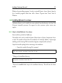
The Qtronic Computation Server can be started by double clicking the "Qtronic 2
Computation Service" icon in desktop (or directly executing qtronic2manager.exe in the
installation directory). Once started, QCS will minimize itself to Windows system tray that
you can see on the lower right hand side of the Windows desktop.
QCS minimized to Windows system tray
2.3.2 How to Uninstall Qtronic 2 on Windows
Qtronic for Windows can be removed from your computer by using a built in feature of
Installing Conformiq Qtronic2
21
Windows for uninstalling programs. In order to uninstall Qtronic, choose Qtronic from the
list of installed programs found from Add or Remove Programs from Control Panel of
Windows.
2.4 Installing Qtronic 2 on Linux
Conformiq Qtronic can be installed on most modern Linux distributions with Intel 586
(Pentium) compatible processors. For support for other processors, please contact your
supplier.
2.4.1 How to Install Qtronic 2 on Linux
Linux installer is provided as a bash script.
The installer can be used to install the Qtronic Eclipse client or Qtronic Computation Server
or both. The installer will also allow the installation of Conformiq Modeler, a light-weight
modeling tool for drawing UML statemachine diagrams, example models, and more.
Unpack the installer package before continuing to the installation:
• Unpack the installer file using tar command
tar xvfz qtronic-<version>-linux-libc-2.4.tgz
* Change to the installation directory
cd qtronic-<version>-linux-libc-2.4
* Execute the install.sh bash script in the installation directory. This will start the Linux
installer.
22
Qtronic2 Manual
./install.sh
The following list detail the process of installing Qtronic to your computer:
1. Specify destination directory for the installation. The default is $HOME/qtronic.
If the installation directory does not exist, the installer will create one. Make sure
that you have permissions to write to the destination directory.
2. Specify whether you want to install Qtronic Computation Server. The default is
yes. If you select server installation, the installer will install the server and database
components to the destination directory, and initialize the database appropriately.
3. Specify whether you want to install Qtronic Eclipse client. The default is yes.
1 If you select the client installation, the installer will prompt you to specify the
location of Eclipse installation. The default location that the installer looks is
$HOME/eclipse.
4. Installer will install the selected set of components to your computer.
5. At your own discretion, you may want to add the directory where Qtronic resides
to your $PATH, or create a symbolic link from '/usr/local/bin' or '/usr/bin' to the
individual executables.
The Qtronic Computation Server can be started by executing command qcs in the installation directory. For example installing QCS to default location, QCS is started as follows:
$HOME/qtronic/qcs
2.4.2 How to Uninstall Qtronic 2 on Linux
• Remove the directory that you originally selected as the destination directory for
the installation. For example, if this directory is $HOME/qtronic, execute
Installing Conformiq Qtronic2
23
rm -rf $HOME/qtronic
* If you created any symbolic links to the executables, remove the symbolic links.
• Remove the Qtronic Eclipse Client "link file" from the Eclipse installation
directory. For example, if the Eclipse installation directory is $HOME/eclipse,
execute
rm $HOME/eclipse/links/com.conformiq.qtronic.client.link
2.5 Checking the QEC Installation
After Qtronic Eclipse Client has been installed, the next step is to check that the plugin has
been properly activated by Eclipse. The most straightforward way is to start Eclipse and select
Window > Open Perspective ... and check that Qtronic is listed there. If not, the most likely
reason is that the Java version that Eclipse is using is not recent enough or similar. See
Section How to Switch to Qtronic Perspective for more information about Qtronic
perspective.
Troubleshooting QEC Installation
If the Qtronic is not listed in the list of available perspectives explained in previous section, it
is recommended that you start troubleshooting by following the steps detailed below:
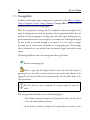
1. Select Window > Show View and select Other. This will open Show view wizard.
2. From Show view wizard, select PDE Runtime > Plug-in Registry. This will open
Plug-in Registry wizard.
3. Locate com.conformiq.qtronic.client from the list of installed Eclipse plug-ins. If
the plug-in is not listed here, the installation has failed and you need to reinstall the
QEC again. Make sure that you have the permission to write to Eclipse installation
24
Qtronic2 Manual
directory.
4. If the com.conformiq.qtronic.client plug-in is listed in Plug-in Registry, check
that the version of Java compiler that Eclipse is using is 1.6 or higher. In case you
have multiple different versions of Java installed on your computer, you may need
to set your PATH environment variable so that it lists Java version 1.6 first before
older versions and to restart Eclipse.
If after taking the steps above, Qtronic is still not registered in Eclipse, please contact
software provider.
Note that plug-in registry is not available in all the Eclipse packages. It is recommended to
use Eclipse Classic.
Checking the Version of QEC
The version of QEC plugin can be checked by selecting Help > About Eclipse SDK. This
will open About Eclipse SDK view where you select Plug-in Details which opens About
Eclipse SDK Plug-ins view. This view will list all the plugins that are installed to the Eclipse
with version numbers. The QEC plugin is provided by Conformiq Software and the plug-in
name is com.conformiq.qtronic.client.
Customizing the Qtronic Perspective
The Qtronic perspective in Eclipse user interface can be customized in number of ways. You
can for example, disable and enable some of the command groups in the tool bar.
In order to add or remove command groups from the tool bar, follow the steps detailed
below
1. Switch to Qtronic perspective, for example by selecting Window > Open
Perspective > Qtronic.
2. Select Window > Customize Perspective.... This will open Customize Perspective
wizard.
Installing Conformiq Qtronic2
25
3. Select the Commands tab.
4. Select the command groups that you want to have in the tool bar from the
Available command groups
i
Use the steps above if for some reason the Qtronic specific commands are not
visible in the tool bar in Qtronic perspective.
2.6 License Management in Qtronic2
Conformiq Qtronic is license managed software. This means that every time you run
Qtronic it checks for an electronic certification of your right to use it. (This does not mean
that Qtronic would contact any service outside your company, for instance, a service
provided by Conformiq Software at its own domain.)
The purpose of the license management features is not to define what your use rights are in
the first place, because this is done in the licensing agreements between you or your
company, and the copyright holders of Conformiq Qtronic. Rather, the license management
features help you to abide within the terms of these agreements.
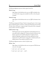
Keeping this in mind, there are three different mechanisms that Qtronic uses to verify your
right to use the software:
• Qtronic evaluation version makes use of evaluation keys, which are short character
sequences looking like APO39-JK119-NCQOL-011LX-ZMNNM. When Qtronic
is running as the evaluation version it will ask for an evaluation key. Evaluation
keys have a limited validity time.
• Other versions of Qtronic, like Qtronic SG, check for a right to use the software at
startup and then regularly until the software is closed.
In the last case, what Qtronic needs is a license grant, which is a small electronic document
(actually, a block of a few lines), that certifies that Qtronic can be used in its present configuration at your local computer node. Qtronic can get access to this license grant in two ways:
26
Qtronic2 Manual
• You can manually cut-and-paste the block into a text edit box in Qtronic via the
GUI's license management features. The license grants fed in by this method are
usually long-term, node-locked grants. This is known as node-locked licensing.
• Qtronic can automatically check out the grants as short-term, renewable grants
from a license server. Qtronic uses web-based license server (but the license server
usually resides at your intranet server rather than in the public Internet). This is
known as floating licensing.
As already implied, there exist different configurations of Conformiq Qtronic. These configurations are not shipped or installed separately. Instead, Conformiq Qtronic can be
configured dynamically to run in any of these configurations. However, because different
configurations have different licensing requirements, probably not all of them are actually
usable for you. If you select a configuration that you do not have a license for, Qtronic will
not work properly but will prompt you about a missing license and guide you to reconfigure
the product.
2.6.1 Configuring Qtronic Feature Set
When you start Conformiq Qtronic for the first time, the tool will immediately ask you for
the product configuration.
If you are conducting an evaluation of Conformiq Qtronic, choose Qtronic Evaluation. In
other cases, choose the Qtronic version that matches your node-locked or floating licenses.
When in doubt here, contact your system administrator.
Qtronic will remember your choice and will not prompt you again for it. However, you can
reconfigure Qtronic at your will by
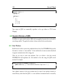
1. selecting Window > Preferences... in the main menu. This will open Preferences
wizard
2. selecting Qtronic > Licensing from the Preferences wizard. This will open the
Qtronic License Management view shown in the figure.
Installing Conformiq Qtronic2
27
Qtronic License Management view
2.6.2 Qtronic Evaluation
Conformiq provides a limited time evaluation licenses for the prospective customers who are
interested to find out the suitability of Conformiq Qtronic to their specific needs and test
environments. Prospects can download an evaluation copy of Conformiq Qtronic from
Conformiq website and request the license online.
28
Qtronic2 Manual
i
The evaluation licenses are node specific: two nodes cannot use the same
evaluation license, but instead a separate evaluation license must be provided for
each distinct node. The evaluation versions of Qtronic can only be run on computers
that can connect to the external internet using the port 80 (HTTP) because Qtronic
Computation Server will check that the given evaluation license is not already registered
to some other node.
i
If you need to use HTTP proxy in order to get access to external network, you
can configure Qtronic Computation Server to use HTTP proxy by setting
http_proxy environment variable before running QCS. In Linux you can do this by
running export http_proxy=http://proxy.mycompany.com in sh/bash/ksh shells and
setenv http_proxy http://proxy.mycompany.com in csh/tcsh shells. In Windows, the
environment variable can be set for example by using the set
http_proxy=http://proxy.mycompany.com command. If your proxy uses login then the
proxy
address
needs
to
be
written
in
the
format
http://user:[email protected]:port in the above commands.
If you are conducting evaluation of Conformiq Qtronic, make sure you have selected the
"Qtronic Evaluation" configuration (see above). If you do not have a valid evaluation license
already installed, Qtronic will ask you for one. Enter the evaluation key you have received
when prompted. Qtronic will notify you about the remaining evaluation time every time you
establish connection to QCS.
If you want to change the evaluation key even while the current key is still valid, follow the
steps detailed below:
1. Select Window > Preferences... in the main menu. This will open Preferences
wizard
2. Select Qtronic > Licensing from the Preferences wizard.
3. Check Evaluation License check box and enter the license text block.
Installing Conformiq Qtronic2
29
Most features of Qtronic are available in the evaluation version.
2.6.3 Node-Locked Licensing
If you have a node-locked license for your configuration and your node, you can provide the
license to Qtronic in the license management dialog.
To configure a node-locked license, follow the steps detailed below:
1. Select Window > Preferences... in the main menu. This will open Preferences
wizard
2. Select Qtronic > Licensing from the Preferences wizard.
3. Check Node-Locked License check box and enter the license text block.
Node-locked licenses are text blocks that start with "#### BEGIN CONFORMIQ
LICENSE GRANT ####" and end with "#### END CONFORMIQ LICENSE GRANT
####". Typically you receive this kind of a license via e-mail. Cut-and-paste the block to the
text box and accept the dialog. Qtronic notifies you whether the license was successfully
added or not.
Qtronic remembers the node-locked licenses you have installed so you do not need to store
the block separately in the file system.
2.6.4 Floating Licensing
To employ floating licensing you must have an installed web-based license server for
Conformiq Qtronic. The administration of the server is described elsewhere; this section
focuses on the use of Conformiq Qtronic given that a license server is running.
To configure the license server into use, follow the steps detailed below:
1. Select Window > Preferences... in the main menu. This will open Preferences
wizard
2. Select Qtronic > Licensing from the Preferences wizard.
30
Qtronic2 Manual
3. Check Floating License check box and enter the base URL for the server. This base
URL you will receive from your system administration, as it depends on where the
license server has been installed.
The URL to the license server binary is the "base URL" that Qtronic users must configure
into their Qtronic installations; for example, "http://server.company.com/cgi-bin/cgiserver.exe". See Section License Server Management for more information.
Usually the license server resides at an intranet web server, so if you have an access to the web
server from the external Internet, it can be possible that you can check out Qtronic licenses
also from outside your local network. How this actually works depends on how your
company has organized external intranet access. Please note that Qtronic does not use https
(secure HTTP) for accessing the license server and therefore cannot log in on a secure web
server, so you may need to have a VPN solution or a local web proxy.
i
The floating license mechanism works also when the license server and licensing
client do not agree on the current (wall-clock) time, but if the time difference is
more than 24 hours in either way licensing will stop working properly. Also, if you
adjust the clock at the licensing client while there are active grants for the client you may
find out that refreshed grants will not work properly. In this case you must wait until
your local license grants have expired and continue using Qtronic only afterwards.
2.6.5 Obtaining Node Identifiers
Some times you need to be able to obtain the node identifier for your local node manually.
The two cases are:
• You are ordering a node-locked license and your supplier must receive the node
identifier in order to bind the license to it.
• You are administrating the license server and you are ordering floating licenses to
it.
Installing Conformiq Qtronic2
31
In order to get the node identifier, open the Preferences wizard and select Qtronic >
Licensing. The node identifier is shown on the bottom of the opened page. You can also
retrieve the node identifier by running the "Conformiq Node Identification" program (cqnode-id in Linux and cq-node-id.exe in Windows). This will show a popup window that
contains your node identifier. When the popup is shown, the node identifier has been copied
on your system's clipboard, so you can immediately paste it in any other application.
i
The purpose of the node identifier is to reliably distinguish between different
machines where Qtronic might be used or a Qtronic license server might be
installed. The node identifier is aggregated from some details of the node's hardware
devices. It is possible, although not usual, that the hardware devices change in a way that
cause the node identifier to change. This may also happen if you enable / disable for
example wireless network devices from BIOS. If you are running floating licensing this is
not a huge problem because the grants for the old node will expire whenever they were
going to expire anyway, after which you can check out grants for the new node. In the
case of node-locked licensing you must contact your supplier who will help you to
transfer you node-locked license to the new node.
2.7 License Server Management
If you want to provide floating licensing to your users you must install the license server.
This is a CGI (Common Gateway Interface) binary thay you install (usually, copy in the
filesystem) into your web server in a location where it can be accessed via an URL.
i
For example, if you are using the Apache web server you must copy the binary to
a directory that has the ExecCGI option set, or that has been set as a general
location for CGI scripts by the ScriptAlias directive.
The server CGI binary will establish a license management database when it is run for the
first time. The location for this database cannot be changed in order to prevent accidentally
32
Qtronic2 Manual
running multiple license server copies. On Windows the location is
C:\WINDOWS\Conformiq\licserv.db and on Linux /etc/conformiq/licserv.db. On both
operating systems the database file is a regular file.
i
The web server must have write access to the directory and the database file when
it is executing the CGI binary.
i
The license database is actually an SQL database that resides inside the file. If you
try to modify the contents of the database by hand you will end up in a situation
where the server says that the integrity checks for the database fail. At this point the
database has been rendered unusable and the license server ceases to work. Do not
modify the database by hand.
Once you have installed the CGI binary (cgiserver.exe) to the correct location, you can
validate that the installation has been succesful by opening the CGI binary via a web browser.
For example, if you installed the binary on an Apache server in its default configuration on
server "server.company.com", try to access it via "http://server.company.com/cgi-bin/cgiserver.exe". If the installation has been succesful and the database created correctly you will
receive a page showing an empty list of licenses and a text box where you can edit text (this
box is used for adding permanent licenses to the server).
The URL to the binary (as above) is the "base URL" that Qtronic users must configure into
their Qtronic installations; for example, "http://server.company.com/cgi-bin/cgiserver.exe".
2.7.1 Viewing Licensing Status
To view the licensing status, just open the CGI binary via a web browser. You will receive a
list of licenses with their corresponding active grants (if any).
Installing Conformiq Qtronic2
33
2.7.2 Adding Licenses
To add licenses to the server, cut-and-paste the license block you have received from your
vendor in the text box that is shown on the status page below the list of licenses and active
grants.
3 Testing with Conformiq Qtronic2
Testing with Conformiq Qtronic2
35
Conformiq Qtronic2 is a tool for offline generation of test scripts (the particular features
available depend on your licensing options). Conformiq Qtronic creates and executes tests
driven by design models. It is not in itself, however, a tool for creating these design models.
The reason for this is that Conformiq Qtronic supports multiple types of design models, and
the different types are created and modified using different tools:
• Java/UML models can be created using text editors and Conformiq Modeler, a
separate tool that is shipped with Qtronic GP.
• Conformiq Qtronic Ecosystem Packages (QEPs) are created using special software
used to manage ecosystem licensing.
• Models created using some of the leading 3rd-party modeling tools.
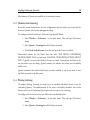
Overview of the Qtronic architecture
To start testing with Conformiq Qtronic one needs first a design model (see Secion
Conformiq Qtronic in Software Process). One also needs further scripting back-end.
i
For more information about creating UML/Java models, see Creating Models in
QML. Scripting backends are discussed in Creating Qtronic2 Scripting
36
Qtronic2 Manual
Backends.
3.1 Quick Start of Using Qtronic 2
The following list summarizes the steps when working with Qtronic 2.
1. Switch to Qtronic perspective by selecting Window > Open Perspective... and
then Qtronic.
2. Select Window > Preferences... to configure license and the QCS server location.
3. Create a new Qtronic project by selecting New > Qtronic Project. This will also
create a Test Design Configuration which 'owns' the coverage settings and scripter
plugins.
4. Select model files to project by either importing or linking them to project.
5. Import model files to QCS by clicking Load model files to Computation Server.
6. Select coverage goals from the test design configuration that was automatically
created when Qtronic project was created.
7. Select Qtronic project and click Properties to configure Qtronic algorithmic
options.
8. Generate test case by clicking Generate Test Cases from Model.
9. Analyze the test generation results in the QEC user interface after the test
generation finishes.
10. Select a scripter plugin by selecting the test design configuration and clicking New
> Scripting Backend.
11. Render the test cases in the format specified by the scripter plugin by clicking
Render All Test Cases.
As discussed in Section How to Work with Qtronic2 Projects it is highly recommended to
Testing with Conformiq Qtronic2
37
store project data locally to prevent any data loss due to network outages or other problems
by selecting Qtronic > Save Project after project has been updated, after changing and
reloading the model, and after generating test cases.
The usual flow in testing with Conformiq Qtronic is very simple as shown in the next few
how-tos.
3.2 How to Switch to Qtronic Perspective
Qtronic perspective in Eclipse is a group of views and editors in the Workbench window.
Qtronic perspective can exist in a single Workbench window with other perspectives.
Switching to Qtronic perspective is carried out by selecting Window > Open Perspective >
Qtronic. If the Qtronic perspective is not visible after selecting Window > Open
Perspective, select Other... from the drop down menu where Qtronic is shown.
The Qtronic perspective looks as shown in the Figure. The different views and editors are
covered in detail in the following sections.
38
Qtronic2 Manual
Qtronic Eclipse Client
3.3 How to Configure Qtronic2 Client
Before loading models or generating any test cases, Qtronic2 Eclipse client must be
configured with the Qtronic computation server address and port number. The server
address can be either a hostname or IP-address. By default, the port number that Qtronic
computation server uses is 2727.
1. Open preferences by selecting Window > Preferences....
2. From Preferences, select Qtronic
3. Enter the address and the port number of the Qtronic computation server
i
The location of QCS is Eclipse workspace specific setting, therefore each Qtronic
project in a Eclipse workspace share the same QCS location. See Section
Managing Qtronic Projects for more information about Eclipse workspaces.
Testing with Conformiq Qtronic2
39
3.4 How to Work with Qtronic2 Projects
Testing setups are managed as projects in Conformiq Qtronic2. They are structural units
that can be opened and closed. Qtronic projects contain the following information:
• Model files
• Test design configurations
• Test generation options
In order to create a new Qtronic project, follow the steps below:
1. On the main menu bar, select File > New Qtronic Project. The New Project
wizard opens.
2. In the Project name field, enter the name of the new Qtronic project.
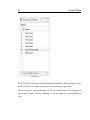
3. Click Finish. This will create a new Qtronic project which will be visible in the
Project Explorer. Note that this operation will also create a single Test Design
Configuration. More information about Test Design Configuration is given in
Section How to Create Test Design Configurations.
40
Qtronic2 Manual
An example Qtronic project in Eclipse Project
Explorer
i
In order to prevent any possible data loss due to network connection problems
with Qtronic Eclipse Client and Qtronic Computation Server, it is highly
recommended that the project data is saved by the user by selecting Qtronic > Save
Project Data after project has been updated, after changing and reloading the model,
and after generating test cases. This will take a snapshot of the server database which can
be restored by the client if server for some reason becomes unavailable and is restarted.
Testing with Conformiq Qtronic2
41
In order to close a Qtronic project, follow the steps below:
1. Select the Qtronic project in the Project Explorer view.
2. Click Close Project in the pop-up menu.
i
It is recommended that you close Qtronic projects when you are not working
with them, because closing of a Qtronic project will free some resources from the
Qtronic Computation Server.
To re-open the Qtronic project:
1. Select the Qtronic project in the Project Explorer view.
2. Click Open Project in the pop-up menu.
To delete a project and remove its contents from the file system:
1. Select the Qtronic project to be removed in Project Explorer view.
2. Click Delete on the pop-up menu.
3. In the dialog that opens select Also delete the contents under ...
4. Click Yes
If you do not wish to delete the contents as well, simply select Do not delete contents from
the opened dialog.
i
If the model files and scripter plugins are imported to the project (the process of
adding model files and scripter plugins to the project is explained later), the
original files are left intact even if you choose Also delete the contents under ... in the
dialog window.
See Section Managing Qtronic Projects for more information about Qtronic projects.
42
Qtronic2 Manual
3.5 How to Select Models
Each Qtronic project contains a folder called model. This is where the model from which the
tests will be generated will reside.
i
The manifest file concept used in Qtronic 1.X is no longer used and the model
files are individually selected to the project instead of a single manifest file.
The first step in importing the model to Qtronic is to add model files to model folder. There
are couple of ways to do this:
This first option is to actually copy the model files to the Qtronic project. This means that
the original model files and imported model files are totally distinct thus changes and not
reflected automatically between these physical resources. The steps to import model files to a
Qtronic project are detailed below:
1. Select model folder under a Qtronic project in Project Explorer
2. Select Import from the pop-up menu. This will open Import wizard.
3. Select General > File System and click Next.
4. Click the Browse button on the opened page to select the directories from which
the model files will be added. Click OK once the directory has been selected.
5. From the pane on the right hand side select those files that are part of the model
and click Finish.
The second option is to create a link to model files in the file system. This means that the
Qtronic project does not contain the model files, but just file links to them. The steps to
create file links to the actual model files are detailed below:
1. Select model folder under a Qtronic project in Project Explorer
2. Select New > File from the pop-up menu. This will open New File wizard.
3. Click Advanced and check Link to file in the file system.
Testing with Conformiq Qtronic2
43
4. Select Browse... which will open a file selector.
5. Navigate to the model file and select OK.
6. Finally click Finish in the New File wizard.
7. Repeat the steps above for each file that is part of the model.
A very convenient way to work with linked resources is to use path variables which are used
to specify locations on the file system. The location of linked resources may be specified
relative to these path variables. By using a path variable, you can share projects containing
linked resources with team members without requiring the exact same directory structure as
on your file system.
Path variables are created as follows
1. Select Window > Preferences.... This will open Preferences wizard.
2. Select General > Workspace > Linked Resources.
3. Select New... and enter the name of the new path variable and the location.
Now when you link a model file to your Qtronic project, you can do it by using this path
variable. Now instead of defining the absolute path to the model file, you select path to the
model file that is relative to the path variable. This way when another member of your team
uses the same Qtronic project, she can redefine the path variable to point to a proper location
in her file system.
See Section Managing Qtronic Projects for more information about Qtronic projects.
Once the model files have been imported from the file system to the Qtronic project, the
model can be loaded to Qtronic computation server by selecting Load Model in the tool bar.
This will send the model files to the Qtronic computation server, which then imports the
model. The status information in addition to warning and error messages is shown in the
Eclipse Console.
44
Qtronic2 Manual
Eclipse console showing results of successful model import
i
Model files are always inserted to model folder. This is where Qtronic will look
for model files, nowhere else. Under model folder, you can have directory
hierarchy so that logically distinct model parts (such as server components and client
components) can be placed into different subdirectories. Note however that all the files
under model directory are treated as part of the model, therefore you cannot place for
example documentation files under model directory.
3.6 How to Create Test Design Configurations
A feature introduced in Qtronic 2.0 is the test design configurations. The test design config-
Testing with Conformiq Qtronic2
45
urations allow user to create different profiles with different coverage settings and scripter
plugins for different testing purposes. For example, user may wish to have a test suite for
verifying very basic requirements of the system and another test suite for verifying very
detailed corner cases such as boundary values of integral comparisons and such. In this
particular case, user can define two distinct test design configurations to a single Qtronic
project: one for verifying the very basic requirements and another for verifying more detailed
corner cases.
Test design configurations contain a set of coverage settings and a set of (possibly an empty
set) of scripter plugins. In order to create a new test design configuration to a Qtronic
project, follow the steps below:
1. Select the Qtronic project in the Project Explorer view.
2. Select New > Test Design Configuration from the pop-up menu. This will open
New Test Design Configuration wizard.
3. Enter the name of the new test design configuration to Test Design Configuration
name field and click Finish.
Create a new Test Design Configuration
Note that when Qtronic project is created, a single Test Design Configuration is created by
default. For more information about creating and working with Qtronic projects, refer to
Section How to Work with Qtronic2 Projects.
46
Qtronic2 Manual
3.7 How to Configure Test Generation
There are two different "types" of test generation parameters in Conformiq Qtronic: those
that are general and global across different test design configurations, and those that are
bound to specific test design configurations. For example, the concepts of lookahead depth
and only finalized runs are generic as they are properties that evolves from the model.
3.7.1 How to Configure Global Testing Parameters
To modify the project wide testing parameters, follow the steps shown below:
1. Select Qtronic project in the Project Explorer
2. Select Properties from the pop-up menu. This will open Properties wizard.
3. Select Qtronic from the left hand side of the view.
Testing with Conformiq Qtronic2
47
Configuration view for Qtronic algorithmic options
The properties shown in the view are the following:
Lookahead Depth
Controls the amount of lookahead for planning the test scripts. The value of the
lookahead corresponds to the number of external input events to the system or
timeouts. Selecting values from the left correspond to lower lookahead values.
When Qtronic plans the tests, it intellectually selects interesting values for data
based on the logic in the design model. If the logic that manipulates the data is
after certain number of external events, the lookahead value must be increased,
because Qtronic must be able to "see" this in order to make decisions on the data
48
Qtronic2 Manual
values. If you set this value to a too low value you can miss some tests (of course,
you will see this from the coverage reporting). On the other hand, having too high
a value can cause very high test generation times. Therefore, reasonable values for
lookahead depth are recommended and you should always start with the lowest
possible value. Practically most often the third level (color cyan) is the highest that
you need to go and if this is not sufficient, it is likely that there is some problem in
the model.
Maximum Delay
Defines the communication slack i.e. the time interval in which it is OK to deliver
a message. Recommended values are from 3 to 10 seconds, but this depends on
your application. As a rule of thumb, the latency value should be at most 1/2 of the
granularity of timeouts in your system if any. For example, if your system has a
timer that expires in ten seconds, you should not use latency value higher than 5
seconds.
Test Suite Options
When 'Only Finalized Runs' is selected, Qtronic will only generate test cases that
end the system in a “clean” state. When this setting is activated, only such test cases
are accepted to the generated test suite that would cause all threads in the model to
terminate. In practice, this usually means that a main statechart has entered one of
its final states.
When 'Stop at 100% Requirement Coverage' is selected, the test generation is automatically
stopped upon reaching 100% requirement coverage, which obviously can mean that test
generatation is topped before reaching 100% final overall coverage.
'Test Case Name Prefix' is used to define the default name prefix that is given to new test
cases. By default this value is 'Test Case ' which means that when a new test case is generated,
they are given names such as 'Test Case 1', 'Test Case 2' and so on. For more information
about naming / renaming test cases, please refer to Section Naming Test Cases.
Testing with Conformiq Qtronic2
i
49
Generic offline test generation parameters may not be changed during offline
script generation so these options are all disabled while generating tests.
3.7.2 How to Configure Design Configuration Specific Testing Parameters
Each test design configuration have their own set of model driven coverage criteria that is used
by Qtronic to select a set of test cases to form a good test suite. The coverage goals are used to
guide Qtronic to look for certain behaviors from models or to enable certain behaviors i.e. to
generate test cases that "cover" the coverage goals in the model whether they are related to
the constructs in state machines (such as states and transitions) or to the constructs in the
action language (such as conditional branching or statements). In Qtronic it is defined that a
test case covers a certain coverage goal if execution of the test against the model itself would
cause the goal to be exercised.
Coverage options are organized into a hierarchy where atomic coverage options are contained
inside groups. The coverage groups are a way to organize and present atomic coverage
options to the user. Each coverage option can have the following setting:
Denotes a target goal. Guides Qtronic to look for behaviors that cover each target
goal.
Denotes an ignored goal ("do not care"). Qtronic will ignore these goals while
generating the tests.
Denotes a blocked goal. Guides Qtronic to omit all the scenarios where the given
coverage option is covered. Thus the distinction with Do not care and Block is that goals
marked as Do not care can still be covered in the generated tests, they are simply not goals
for the tool. Qtronic will not generate such a test that would exercise a blocked coverage
option, therefore with blocked coverage options user can prevent Qtronic from generating
50
Qtronic2 Manual
such test cases that realize certain unwanted test scenarios.
The fourth option is Inherit i.e., coverage option inherits the setting from the coverage group
containing the coverage option.
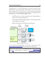
The Coverage Editor is used to set coverage settings. In order to open the view double click
test design configuration under a Qtronic project in Project Explorer. This will open the
view as shown in the Figure. Note that the view only contains relevant information once the
model has been loaded to the Qtronic computation server. In this view, there are two
columns for each test design configuration: the left hand side corresponds to the coverage
setting (intention) and the right hand side column corresponds to the current coverage status
(result). When the cell is edited (left hand side column), the coverage status will be kept as it
is, but the test design configuration name in the column header is appended with *
-character. When test generation is finished (completed), this * -character is cleared.
Testing with Conformiq Qtronic2
51
Selecting model driven coverage criteria in Coverage Editor
See Section Coverage Editor for more information about analyzing coverage status
information.
i
With enhanced coverage goal setting features introduced in Qtronic 2.0 users
have finer grained control over selected structural features enabling users to set
coverage setting to individual structural features: now users can select only an interesting
52
Qtronic2 Manual
subset of the structural features instead of having to set all the coverage goals related to a
given structural feature or none of them.
The following coverage settings are related to state machines and they are not visible if there
are no state machines in the model.
State Coverage
Guides Qtronic to look for behaviors that cover every UML level state at least once
(not visible if there are no states in the model).
Transition Coverage
Guides Qtronic to look for behaviors that cover every UML level transition at least
once (not visible if there are no transitions in the model).
2-Transition Coverage
Guides Qtronic to look for behaviors that cover every pair of two subsequent UML
level transitions at least once (not visible if there are no transitions in the model).
Implicit Consumption
Guides Qtronic to test that the system correctly ignores messages that are not
handled on any transitions going out from a UML state. A word of warning,
though. Enabling implicit consumption may not be what you really want. Without
implicit consumption selected, Qtronic focuses testing on the explicitly modeled
message handlers. With implicit consumption, Qtronic may send to the system
also messages that are not handled in your UML diagrams.
The following configuration options are related to conditional branching. These options are
not visible if there are no such a conditional branching in the model.
Boundary Value Analysis
Guides Qtronic to look for behaviors that cover the boundary value cases for all the
arithmetic comparisons. Boundary value analysis is a technique to determine tests
Testing with Conformiq Qtronic2
53
covering known areas of frequent problems at the boundaries of input ranges.
In boundary value analysis the boundaries partition the input domain and we assume that
the system partitions the input into a set of domains in which the systems behavior is similar.
Due to this, we assume that if an input from a domain causes an error then all the inputs of
that domain will cases a similar error and if an input from a domain does not cases an error
then all the inputs of that domain will fail to produce an error.
Based on these assumptions, Qtronic attempts to cover the structure of the input as follows:
• For every arithmetic comparison 'x = y' and 'x != y' cover cases 'x < y', 'x = y', and
'x > y'
• For every arithmetic comparison 'x < y' cover cases 'x < y - 1', 'x = y - 1', 'x = y',
and 'x > y'
• For every arithmetic comparison 'x <= y' cover cases 'x <= y - 1', 'x = y', 'x = y + 1',
and 'x > y + 1'
Branch Coverage
Guides Qtronic to look for behaviors that cover every QML level branch (such as
then and else branches of if statements) at least once.
Atomic Condition Coverage
Guides Qtronic to look for behaviors that cover every QML level atomic condition
branch (such as left and right hand sides of a Boolean and) at least once. Note that
because the modeling language uses short-circuit evaluation for Boolean
connectives, there are value combinations that cannot be meaningfully tested in
general. For example, in the case of x && y, Qtronic will not attempt to generate
a test case where 'x' would be false and 'y' would be true. The reason is that the
short-circuit evaluation rule will cause the evaluation of the condition to cease after
it has been found out that 'x' evaluates to false, which makes it possible that the
value of 'y' may depend on the assumption that 'x' evaluates to true. (Note that 'x'
and 'y' can be both e.g. method calls).
54
Qtronic2 Manual
The following configuration options are related to general control flow.
Method Coverage
Guides Qtronic to look for behaviors that cover every QML level method at least
once. Note that this coverage option essentially has no effect on the values passed
to methods.
Statement Coverage
Guides Qtronic to look for behaviors that cover every QML level statement at least
once.
The following coverage options belong to "dynamic coverage goals" group i.e. these coverage
goals are calculated by Qtronic on-the-fly as it analyses the model. Because of this on-the-fly
calculation, Qtronic will not give coverage percentage for these goals and these coverage goals
do not have effect to the final coverage figures.
Parallel transition coverage
Parallel transition option is used to guide Qtronic to look for behaviors that cover
every parallel transition configuration. The major new benefit of this feature is that
Qtronic can generate tests for parallel configurations of components that are
modeled as independent components that can interact maliciously in the real
implementation. As parallel transition coverage goals are calculated on-the-fly, also
multiple instances of a state machine are taken into account.
The following configurations options are related to all paths coverage.
All Paths - States
Guides Qtronic to look for behaviors that cover every sequence of UML level states
at least once. For example:
1. initial - state1 - state2 - state3 - state4
2. initial - state1 - state3 - state6 - ... - stateN ...
Testing with Conformiq Qtronic2
55
All Paths - Transitions
Guides Qtronic to look for behaviors that cover every sequence of UML level
transitions at least once. For example:
1. initial->state1 - state1->state2 - ...
2. initial->state1 - state1->state3 - ... ...
All Paths - Control Flow
Guides Qtronic to look for behaviors that cover every sequence of conditional
branches (f.ex. then and else branches of if statements) at least once.
If you have multiple "all paths" coverage options selected, you get combinations of the above
sequences as result.
In addition to the different coverage criteria based on the structure of the model described
above, the user has the option to use requirements traceability links to establish additional test
goals driven by functional requirements and testing goals (The requirement links are marked
in to the model using requirement statement that is an extension to standard Java
provided by the QML language. See Section Requirements for more information.).
Requirements provide a way to drive test generation by coverage of external functional
requirements.
3.8 How to Generate Tests
Once the model files have been selected, the model has been imported to the Qtronic
computation server, and the coverage settings have been properly set for the test design
configurations, the test generation can be triggered by selecting Update Test Set. This will
trigger the test generation on the Qtronic computation server.
As the test generation progresses, the Eclipse console window will show the status of the test
generation. In addition the coverage editor will show the coverage status real-time i.e. what are
the so far covered aspects and what is still left to cover for Qtronic.
56
Qtronic2 Manual
Status of test generation shown in Eclipse console
Once the test generation finishes, the final coverage will be shown in the Eclipse console as
well as the final coverage of each requirement and structural feature in the coverage editor. In
addition, the test generation results will be shown in various views in the Eclipse user
interface, a subject of the next section.
Test generation can be stopped manually also before the test generation finishes. This can be
done by opening the Progress wizard for example by double clicking the status text on the
lower right hand side of the Eclipse user interface and by clicking the red box with Cancel
Operation label. When the test generation is manually stopped, QEC will present you two
possibilities:
• Merge the test generation results, meaning that all the generated test cases
generated up till the moment the test generation was stopped are merged to
existing set of test cases.
• Discard the test generation results, meaning that all the generated test cases
Testing with Conformiq Qtronic2
57
generated up till the moment the test generation was stopped are discarded and
existing set of test cases will stay the same as before.
3.9 How to Analyze Test Generation Results
When generating test cases, Conformiq Qtronic maps the test cases to the different test goals
induced by the coverage settings as explained in Section How to Configure Design Configuration Specific Testing Parameters. It then selects from the test cases it has constructed a sub
set that covers all the found test goals using a minimal cost test suite, where the cost of an
individual test case is the number of messages in it squared. This ensures that the suite is
reasonably small and compact but at the same time the individual test cases remain relatively
short, which eases test execution and debugging. In addition to this, Conformiq Qtronic also
prefers to cover all test goals as early as possible, i.e. after as few messages as possible,
providing better separation of concerns between test cases.
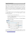
Once the test generation finishes, the Eclipse user interface shows a number of different
views that can be used to analyze the test generation results: in Qtronic 2.X the generated
tests are visible in the user interface allowing user to do detailed analysis of the generated
tests. The views that are available for test generation result analysis are the following:
• Coverage Editor shows the final status of black-box coverage figures.
• Test Case List shows all the generated test cases with the generation date and the
name of the test case where user can also rename the test cases.
• Traceability Matrix View correlates the coverage options to the test cases that
"covers" them.
• Test Case View shows the interaction between the tester and the system under test.
• Test Step View shows detailed information about the messages that are transfered
between the tester and system under test in the given test case.
• Execution Trace View links back the test case back to the model from which it was
generated on a rudimentary way.
58
Qtronic2 Manual
3.9.1 Coverage Editor
In addition to selecting the target coverage goals (as explained in Section How to Configure
Design Configuration Specific Testing Parameters) Coverage Editor can also be used to
analyze the status of black-box coverage figures.
While the test generation is running, this view is updated in real-time providing user the
means of analyzing the status of the test generation. Once test generation finishes, this view
will show the final coverage figures. Coverage status cells can be empty (indicating that the
goal was uncovered because it was not targeted), it can contain icon (indicating that the goal
has been covered or uncovered although it was targeted), or it can contain a coverage
percentage value in case the status corresponds to a coverage goal group. This percentage
value is calculated by the user interface from the intentions (targets) and results (covered
targets).
The meaning of different icons in the coverage status cells are given below:
Denotes a covered target goal.
Denotes a target goal that Qtronic failed to cover. Note that while Qtronic is
generating the test cases, there is no status icon for the given atomic goal. However, if the
target goal is still uncovered when the test generation stops, this icon will be shown in the
QEC user interface.
i
Note that when the tests are generated, the coverage setting cells cannot be
edited.
If the test generation is aborted by the user, the following happens
• If user decides to merge the changes, the Coverage Editor is left to the state that it
is (as it was already updated in real-time).
• If user decides to unroll the changes, the Coverage Editor is reverted to a state
Testing with Conformiq Qtronic2
59
before the test generation.
User has several possibilities to filter information in the Coverage Editor using the filtering
buttons in the Eclipse menu bar:
Denotes a filter for unaffected settings i.e. when this filter is enabled the view will
only show those cells that have been edited since last test generation or that have never been
used in test generation (thus each cell is in "edited state" initially, until tests are generated
according to its initial setting).
Denotes a filter for "overridden" settings i.e. when this filter is enabled the view will
only show those cells that are not "inherited".
Denotes a filter for uncovered target goals i.e. when this filter is enabled the view
will only show those cells that show a target goal (intension) that Qtronic failed to cover.
3.9.2 Test Case List
The Test Case List will show the list of generated test case once Qtronic computation engine
has finished with the test generation with the names and creation dates as shown in the
Figure.
The Test Case View can be opened by selecting Window > Show View > Test Case List.
60
Qtronic2 Manual
Test Case List
In the Test Case View the test cases can be named and renamed by double clicking a test case
in the view. The test case names stay persistent over consecutive test generations.
The test cases can be sorted in the view by any of the visible columns. User can also search
for test cases by name by writing a substring of a test case name in to text field above the
view.
Testing with Conformiq Qtronic2
61
3.9.3 Traceability Matrix View
A Traceability Matrix is a table that correlates the coverage goals (structural features and
high-level testing requirements) to the matching parts of test cases in many-to-many
relationship. The column on the left in the traceability matrix shows the coverage goals and
the number of the test cases are placed across the top row. There is a marking cross in the
intersecting cell when the coverage goal in the left column is covered in the test case in the
top row.
The Traceability Matrix View can be opened by selecting Window > Show View >
Traceability Matrix.
62
Qtronic2 Manual
Traceability Matrix
The coverage goal groups can be expanded and collapsed by the user. If a particular test case
is active and shown in the matrix, the corresponding column is highlighted.
3.9.4 Test Case View
The Test Case View shows the flow of logic within the test case i.e. the interaction between
the tester and the system under test (Tester and SUT in the view). The tester and the system
Testing with Conformiq Qtronic2
63
under test are represented as parallel vertical lines ("lifelines") representing the life span of the
object during the test scenario. The message take-overs between them is represented with
horizontal arrows augmented with the name of the message being transfered, the name of the
port, and the exact time stamp at which the message is transfered.
The Test Case View can be opened by selecting Window > Show View > Test Case View.
Message Sequence Chart of a test case
In order to also see how internal model threads interact, you can open extended Test Case
64
Qtronic2 Manual
View by clicking Show all messages on top of the view. Extended view will show the tester as
the left most lifeline and each named internal thread as a separate lifeline on right from the
tester lifeline. The extended view will also show all the internal message take-overs between
the internal threads.
To get back to the basic view i.e. to see only the interaction between the tester and the SUT,
click Show external messages only on top of the view.
There are also two filters in the top of the view for showing and hiding coverage goals that
are covered by the test case:
Show/hide covered requirements is used to filter the covered requirements.
Show/hide covered structural features is used to filter the covered structural
features.
3.9.5 Test Step View
The Test Case View shows the interaction between the tester and the SUT with name of the
messages that are transfered. The Test Step View shows more detailed information about the
message content. The following information can be obtained from this view:
• The number of the test step. The first test step in the test case is always 1.
• The name of the type of the message being transfered between objects.
• The name of the port to which the message was sent to.
• The time stamp of the test step i.e. at what time was the message transfered.
• The content of the structural message with the field name and field value. See
Section Record Types for more information about structural messages.
The Test Step View can be opened by selecting Window > Show View > Test Step View.
Testing with Conformiq Qtronic2
Test Step View showing content of test steps
65
66
Qtronic2 Manual
3.9.6 Execution Trace View
The Execution Trace View shows the execution trace of the test case in the model i.e. the
execution path in the model that would be seen if the test case would be executed against the
model itself. The information in the view is shown graphically so that each state machine
level state is represented as a rounded box with the name of the state inside it, the state
machine level transitions (i.e. the transfer of control from one state machine level state to
another) are represented as arrows between the states, and action language level method
invocation are represented as text.
In essence, the Execution Trace View provides a rudimentary way to link back the generated
tests to the model from which the tests were generated by showing the execution flow in the
model.
The Execution Trace View can be opened by selecting Window > Show View > Execution
Trace View.
Execution Trace View
3.9.7 Analyzing Model Defects
System models document the desired functionality of the system; model driven testing turns
Testing with Conformiq Qtronic2
67
these functional requirements into valuable testing assets. It is correct to see a system model
as a golden reference implementation of the system. However, since system models are
human made, they may contain errors.
While performing the test generation, Qtronic also verifies that the model is internally
consistent i.e. the tool will check the absence of internal computation errors (such as division
by zero) while it analyzed the model. If the model contains internal computation errors,
Qtronic reports these defects by showing the call stack trace and the IO trace that leads to the
particular error.
The figure shows an example of such an internal computation error where the model
contains a division by zero.
Analyzing an internal computation error in a model
i
Note that information about encountered model defects are reset in the tool
when tests are regenerated: there will be no useful information about model
68
Qtronic2 Manual
crashes that have happened in previous test generation runs available in the tool.
3.10 How to Export Test Cases
There are software processes wherein it is beneficial to generate separate test scripts that can
be stored in version control systems, maybe sent around, and executed independently
afterwards. To meet this need, Qtronic provides the means for generating test scripts from
system models where test cases are derived automatically from a functional design model and
can be executed against a real system.
Simply, a scripting back-end is a scripting backend that is connected to Conformiq Qtronic
using a well-defined API. These scripters can be created by the organization that employs
Conformiq Qtronic for testing, or they can be outsourced or, in some cases, bought as offthe-self software components.
i
In 2.X the scripting backends are Java archives and Java is the programming
language used to implement scripting backends.
Conformiq Qtronic2 is shipped with a number of scripting back-ends.
• An HTML script backend for generating browsable HTML documents.
• A TTCN-3 script backend for generating test script in TTCN-3 which enables
employment of model driven testing in a TTCN-3 environment.
• A TCL script backend for generating test scripts in TCL.
Each test design configuration can contain more than one scripting backends.
The scripting backends are added to test design configurations as follows:
1. Select a test design configuration from the Project Explorer to which the scripter is
added.
Testing with Conformiq Qtronic2
69
2. Select New > Scripting Backend from the pop-up menu. This will open New
Scripting Backend Configuration wizard.
3. Enter the path to the scripting backend or locate the scripting backend by clicking
Browse.
4. Once the scripting backend has been specified, click Finish.
The next step is to configure the selected scripting backend. This is carried out as follows:
1. Select the scripting backend from the Project Explorer you wish to configure.
2. Select Properties from the pop-up menu. This will open Properties wizard where
you see all the scripter specific configuration options.
3. Configure the scripter.
4. Once the scripter has been properly configured, click OK.
70
Qtronic2 Manual
Configuration for TCL scripter
i
Note that the configuration is scripting backend specific. Section How to Use
Script Backends Shipped with Qtronic2 details how to configure scripting
backends shipped with Qtronic 2.
The Qtronic generated test cases can then be exported by clicking Render Test Cases.
i
Note that selected scripting backends can be enabled and disabled. By default, all
the scripting backends are enabled. In order to disable a scripting backend, select
Testing with Conformiq Qtronic2
71
the scripting backend from the Project Explorer view, and select Disable from the popup menu. The scripter can be re-enabled similarly.
3.10.1 How to Use Script Backends Shipped with Qtronic2
This section describes how to configure script backends that are shipped with Qtronic.
How to Use HTML Script Backend
The HTML script back-end saves the log as an HTML file. A generated HTML file can be
viewed with any modern web browser that supports JavaScripts and Cascading Style Sheets.
The HTML script backend is configured using the following configuration options:
Main / Generated HTML file
Selects the output file. The output file name should have the format
<DIRECTORY>/<INDEX PAGE>.html, for example /tmp/testcases.html or
C:\testcases.html.
Customizations / Multi page output
set to "yes" or "no". If set to "yes", each test case is generated to a separate file. In
addition, an index page is generated that contains hyper links to the test case files.
Customizations / Separate lifelines for ports
Show separate lifelines also for ports in tester side. The default value is "no" in
which case only lifelines for tester and for all the threads active in the given test
case will be visible.
Customizations / Input port suffix
Omit port suffix from an input port. With this option it is possible to combine
lifelines of unidirectional input and output ports to a single lifeline that represents
a single bidirectional port. This option is only applicable when "Separate lifelines
72
Qtronic2 Manual
for ports" is set to "yes". The default value is "_in". For example, if the model
contains input port "X_in", and output port "X_out", and both "Input port suffix"
and "Output port suffix" have been left to default values, the plugin generates a
separate lifeline named "X", which contains both input of "X_in" and outputs of
"X_out".
Customizations / Output port suffix
Omit port suffix from an output port. With this option it is possible to combine
lifelines of unidirectional input and output ports to a single lifeline that represents
a single bidirectional port. This option is only applicable when "Separate lifelines
for ports" is set to "yes". The default value is "_out".
How to Use TTCN-3 Script Backend
A TTCN-3 script backend for generating test script in TTCN-3 which enables employment
of model driven testing in a TTCN-3 environment. With TTCN-3 script back-end,
TTCN-3 test cases can be derived automatically from a functional design model and be
executed against a real system.
The TTCN-3 script backend is configured using the following configuration options:
Main / Generated TTCN-3 file
Selects the output file. The output file name should have the format
<DIRECTORY>/<MODULE>.ttcn3, for example /tmp/out.ttcn3 or
C:\out.ttcn3. The <MODULE> part is used automatically as the name of the
generated TTCN-3 module so it should be an acceptable TTCN-3 literal.
Customization / Extra import statements
TTCN-3 code that is included in verbatim at the beginning of the generated
module. Add semicolon if not empty, e.g. "import from MyModule all;".
Customization / Generate data and system types
set to "yes" or "no". If set to "yes", Qtronic generates TTCN-3 records and default
Testing with Conformiq Qtronic2
73
templates based on the types in the model, and also generates system type for the
system type defined in the "System type name" option field. If "no", record and
port types, default templates and system type must be provided by importing.
Customization / System type name
the type name of the system / MTC the test cases run on.
Customization / Start test case hook call
a function call that will be embedded in every test case just before the (optional)
activation of default. If not empty, semicolon is added automatically so you can
have e.g. "start_case()".
Customization / End test case hook call
a function call that will be embedded in every test case just after the deactivation of
the optionally activated default, and also in the Qtronic-generated default in the
case of an unexpected event that causes test case to fail.
Customization / Activated default
default to activate for test cases. Have the complete call (with parameters if needed)
but without semicolon here. If empty, no default is activated (but you can still
activate and deactivate defaults in the hooks).
Customization / Global timer name
name of the timer Qtronic uses to follow-up with wall clock to make sure tests
time correctly. If Qtronic generated system type is used, this timer is embedded in
it, but if you import a system type, a timer with this name must be declared
therein.
Timing / Communications slack limit
allowance for delay in expected input messages before a failure is triggered. For
example, if model predicts a message M at time 5.0 and slack limit is 10.0, failure
to receive M is indicated at time 5.0 + 10.0 = 15.0.
74
Qtronic2 Manual
Logging / Log checkpoints
if true, add log statements for coverage goals.
Logging / Name of the 'log' command
call used to make log statements. "log" comes from TTCN-3 standard, but you can
have a customized routine, import it via the extra imports feature, and then use the
customized routine instead here.
Qtronic assumes that for every record type RecordType there exists a template with the name
DefaultRecordTypeTemplate, which is then modified in the test data declarations.
How to Use TCL Script Backend
A TCL script backend for generating test script in TCL which enables employment of model
driven testing in a TCL environment. With TCL script back-end, TCL test cases can be
derived automatically from a functional design model and be executed against a real system.
The TCL script backend is configured using the following configuration options:
Main / Generated TCL file
Selects the output file. The output file name should have the format
<DIRECTORY>/<SCRIPT>.tcl, for example /tmp/out.tcl or C:\out.tcl.
Test case template / Template TCL file
the location of test case template used. This file contains extra code that can be
inserted before and after Qtronic generated test cases, such as initialization and deinitialization of a test harness.
Test case template / Generate stub template
generate a stub test case template file if one does not exists.
Library / Library TCL file
the location of the TCL library file, i.e. the library file which contains the
Testing with Conformiq Qtronic2
75
implementation of the routines that the scripter generates
Library / Library include method (source|embed)
source / embed the generated library to the script
Library / Generate stub library
generate a stub library file if one does not exist that contains the default implementation of the routines that the scripter generates
Customizations / Array member separator
the separator of QML level array members in TCL
Customizations / Omit port prefixes (port_in -> in)
omit QML port prefixes, i.e. convert port names such as "some_port_in" to "in"
Customizations / RSD-RT Model
Enable conventions of RSD-RT to be used in the generated script. Disabled by
default but can be disabled by setting this option to "yes".
Customizations / Dump Qtronic configuration
Dump the configuration of Qtronic to the beginning of script file. This configuration information includes for example the name of the Qtronic project from
which the script has been generated, all the algorithmic options, and all the
coverage settings. Enabled by default but can be disabled by setting this option to
"no".
Customizations / Highlight actions in code
Surround test steps in the script with comment blocks so that they because
"highlighted" in the generated script. Disabled by default but can be disabled by
setting this option to "yes".
Customizations / Add indexes to variable names
Append an index number to generated variable names. Enabling this option
76
Qtronic2 Manual
prevents variable name clashes, but can be disabled by setting the option to "no".
3.11 Test Case Management
The generated test cases in Conformiq Qtronic 2 can be managed and analyzed in the
Qtronic Eclipse user interface. The different views that can be used in test generation result
analysis were covered in Section How to Analyze Test Generation Results. Test Case
Management is another very important new feature in Qtronic 2.X series: the results of test
generation runs are stored to a persistent data storage that can be managed using the Qtronic
UI.
Persistent Storage for Test Cases
Conformiq Qtronic 2 stores the results of test generation to a persistent data storage every
time the test cases are updated. This means that the results from the past test generation runs
are not lost if the model is updated and the test cases are regenerated. However, when the
model is updated, the updates may render some of the existing test cases invalid as they do
not reflect the external behavior of the model anymore. Also, all those test cases become
invalid that cover features in the model that were previously targets (or "do not cares") but
are now blocked (See Section How to Configure Design Configuration Specific Testing
Parameters for more information about coverage options and settings).
i
The previously generated test results are also used as an incremental input for
future test generations: When generating test cases, Qtronic first analyzes existing
test cases to see which of them are still valid with respect to the external behavior of the
model. Once the incremental analysis is over, Qtronic runs incremental algorithm to
augment the existing test set with additional test cases only if this is required. When tests
are regenerated due to a change in the model etc. there is no need to regenerate tests
from the parts of the model that are not changed. Thus, if the existing test set covers all
the target coverage goals (See Section How to Configure Design Configuration Specific
Testing Parameters for more information about coverage goals), there is no need to
Testing with Conformiq Qtronic2
77
generate more test cases, and Qtronic will stop before running the incremental test
generation algorithm.
When analyzing the test generation results, the following rules apply to representation of the
generated test cases, whether valid or invalid:
• When you click a Qtronic project in the Project Explorer of Qtronic Eclipse user
interface, the Test Case List view will show all the generated test cases for that
project: you see all the test cases from all the test design configurations that are part
of the particular Qtronic project. This set of test cases also includes those test cases
that are no longer valid i.e. test cases that do not represent the updated external
behavior that the model exhibits. These invalid test cases are presented in red font
to differentiate them from the valid test cases that properly represents the behavior.
• When you click a test design configuration in the Project Explorer of Qtronic UI,
the Test Case List view will show only those test cases that were generated using the
test design configuration specific coverage settings. In addition, this view always
shows only valid test cases, never invalid.
i
A test case can "belong" to multiple test design configurations at the same time
because it can be valid over multiple test design configurations i.e. a test case can
be shared by more than one test design configuration.
i
Note that because scripter plugins are always part of test design configurations,
when test cases are rendered, only those test cases that belong to the given test
design configuration are rendered using the particular scripter plugin. There is no way to
render invalid test cases.
If the update to the model that caused invalidation of some test case is reverted, the
invalidated test case becomes valid once again so it is "moved" back to the test design config-
78
Qtronic2 Manual
urations where the test case was valid in the beginning. In addition, this test case is once
again marked as valid in the project wide test case list (i.e. it is not rendered in red font).
Naming Test Cases
As mentioned in Section Test Case List, the generated test cases have names so they can be
identified and differentiated from one another. As the test cases are persistent, also the names
of the test cases are persistent, and they remain the same even if the test cases are regenerated.
By default, the test cases are named with 'Test Case ' prefix meaning that the names given to
new test cases by default are 'Test Case 1', 'Test Case 2', and so on. In addition to renaming
test cases one by one, you can also set the default test case name prefix in Qtronic
Algorithmic Options -property page explained in Section How to Configure Global Testing
Parameters.
The test cases can be named in the Test Case List view by double clicking the test case shown
in the view.
Deleting Test Cases
The generated test cases are stored in to a persistent data storage and they remain "live"
across model reloads and test generations. However, if you wish to delete one or more test
case for a reason or another, this can be done in the Qtronic Eclipse user interface as follows:
In order to delete a single test case:
1. Select the test case in the Test Case List view.
2. Press Delete button
The following rules apply when deleting single test case at a time.
• When a particular test design configuration is selected and a test case is deleted, the
test case is only deleted from the given test design configuration and will remain in
other test design configurations and in the Qtronic project to which the test design
configuration belongs to.
Testing with Conformiq Qtronic2
79
• When Qtronic project is selected a deletion of a test case will delete the given test
case also from all the test design configurations that belong to the project.
In order to delete all the test cases owned by the Qtronic project
1. Select the Qtronic project in the Project Explorer view.
2. Select Qtronic > Delete Test Cases from the pop-up menu. This will delete all the
test cases owned by the project.
i
Note also that when test cases are deleted from the project, there are no
incremental test assets for future test generation runs: Instead, Qtronic needs to
start the test generation all over again.
i
WARNING There is no way to undo test case deletion from a project: deleted
test cases are immediately deleted from the persistent data storage.
3.12 Managing Qtronic Projects
The central hub for data files in Eclipse is called a workspace. Each of these workspace houses
a collection of projects that were already discussed in Section How to Work with Qtronic2
Projects. Each project is stored in to the file system under the workspace location. Each
project folder stored in to the file system contains information related to the given Qtronic
project, namely model files, coverage settings, generated results, and so on.
i
It is recommended to generate a distinct workspace for Qtronic related projects.
This makes it more convenient to work with different Eclipse based applications:
whenever you start a new Eclipse based application, you give them their own workspace.
Switching between different projects is flexible this way, because instead of opening and
closing different projects and trying to find the right project to work with, you just
80
Qtronic2 Manual
switch workspaces entirely. The current workspace for Eclipse can be switched by
selecting File > Switch Workspace from the Eclipse menu bar.
As the workspace is the central hub for the user data files and project folders it contains all
the information for each Qtronic project, it is the Qtronic project folder that is stored into
version control system or sent around to another computer. The structure below represents
an example Eclipse workspace containing a Qtronic project name SIPClient:
workspace
Qtronic
SIPClient
.dbdump
.project
.qtronic
model
SIPClient.cqa
SIPClient.xmi
As mentioned in Section How to Select Models, model files can be either imported (copied)
to the project folder or we can establish file links to model files. In the former case, also the
actual model files are stored to version control while in the latter one, only the file link to
actual model file is stored, not the model file itself.
In addition of being storage location for example for model files and several configuration
settings, Qtonic project also contains all the information about the test generation results.
Therefore, by sharing the Qtronic project with other users (via version control, for example)
enables them to get access to the test generation results as well.
4 Creating Models in QML
82
Qtronic2 Manual
One of the formalisms that can be used to express design models is Qtronic Modelling
Language (QML). In QML, design models can be expressed entirely using the textual
notation, which is essentially a superset of Java with some ideas from C#, or with the
graphical notation, where models are described using UML state machines with the QML
textual notation as an action language.
Note that while design models can be expressed in QML (amongst others), Qtronic
internally uses CQλ (which is a variant of LISP, more exactly a variant of the Scheme
programming language) and QML models are compiled into CQλ before Qtronic testing
engine is started.
4.1 Textual Notation of QML
QML is an object-oriented language that can be used to describe design models. The textual
notation is essentially a superset of Java with some variations. In this document we only
describe those features of QML textual notation that are different from "standard Java".
At a glance, compared to standard Java, the QML language is restricted or enhanced in a few
ways, including but not limited to the following:
• There can be global variables and global methods. Globals have public visibility.
• The main entry point is not a static member method like in Java, but rather a
global function that takes no parameters and returns nothing. The name of the
main entry point is main just like in C and C++.
• Generics in QML are not implemented as in Java 5.0 by using type erasure, but
rather as templates like in C++. In this regard, Java generics are very different from
QML templates: QML produces different types for each distinct template instantiation, which means that also primitive types and methods can be used as template
arguments. Because of type erasure in Java, Java does not support arrays of parameterized types, while QML does.
• The Syntax for invoking template methods is different from Java. In QML, type
parameters are placed after the method name like in C++, rather than before.
Creating Models in QML
83
• There is no boxing/unboxing of types, because it is not required. QML has
nullable types (like in C#) which address the scenario where you want to be able to
have a primitive type with a null value.
• In addition to reference types (classes and arrays), QML has also support for
structured value type records.
• The inner classes in QML are semantically closer to the nested classes of C++
rather than the inner classes of Java. The inner classes in QML are roughly
equivalent to the static inner classes of Java.
• There are no anonymous inner classes or records in QML.
• Communication with the environment is carried out by using ports that are
declared inside a system block.
• QML supports operator overloading.
• QML supports type aliases through typedef keyword like in C and C++.
• QML supports implicit types for local variables: once an implicit type has been
inferred during compilation it does not change.
• Currently there is no support for packages.
• Currently there are no enumerators.
• Annotations are not supported.
• goto and labeled break and continue are not supported in QML.
• All the user defined types have global visibility.
• The standard library of QML is very limited compared to the standard library of
Java.
The convention is to name the QML textual notation files with the .cqa suffix.
84
Qtronic2 Manual
4.2 Basic Language Features
The following topics introduce and discuss the essential components of the QML textual
notation, a language for defining design models.
4.2.1 Keywords
The keywords of the QML textual notation are listed in the table below.
Keyword
abstract
after
and
assert
boolean
break
byte
case
catch
char
class
complete
const
continue
default
do
double
Meaning
An abstract class or method.
An after event (from UML).
A logical AND (an alias to &&).
An assert that a condition holds.
A boolean type.
Break out from a loop or switch case
statement.
An 8-bit integer type.
A case of a switch case.
A clause of a try block catching an
exception.
A character type.
A class type definition (classes are reference
types).
Indicates end of an incomplete region of
model. See Section End Conditions for Test
Generation for details.
A constant.
Continues to the end of a loop.
The default clause of a switch case.
The top of a do while loop.
An arbitrary precision floating point number
Creating Models in QML
else
enum
extends
final
finally
float
for
goto
if
implements
import
Inbound
incomplete
instanceof
int
interface
long
85
(an alias to float).
The else clause of an if statement,
An enumerated type (currently not
supported).
A super class definition (parent) of a class or
a super record of a record.
A constant or a class, a record, or a method
that cannot be reimplemented.
A clause of a try statement that is always
executed after exiting try block.
An arbitrary precision floating point
number.
A for loop.
QML does not support gotos.
A conditional statement.
Defines the list of interfaces that the class or
record implements.
Import a library. All the libraries in QML
are in the conformiq namespace.
Defines an external inbound port in the
system block.
Indicates beginning of an incomplete region
of model. See Section End Conditions for
Test Generation for details.
Tests if a variable is an instance of a type
(this is not restricted to reference types as in
Java).
An arbitrary precision integer.
An abstract type with methods that the class
or record must implement.
An arbitrary precision integer (an alias to
86
Qtronic2 Manual
int).
native
new
nocoverage
null
Outbound
omit
operator
or
package
priority
private
probability
protected
public
record
Not supported.
Allocates a new object or an array. Note that
records are not created with new.
Marks a region with no coverage goals
attached. See Section Regions with No
Coverage Goals for more details.
The nil reference.
Defines an external outbound port in the
system block.
The omit keyword specifies that the record
field is omitted from the record instance.
Provided for backward compatibility with
Conformiq Test Generator adapters.
Overloads an operator.
A logical OR (an alias to ||).
Not supported.
Adds a priority to model. See Section
Probabilities and Priorities for details.
A private modifier — a feature that is
accessible only by the methods of this class
or record.
Adds a probability to model. See Section
Probabilities and Priorities for details.
A protected modifier — a feature that is
accessible by the methods of this class or
record and in all the subtypes.
A public modifier — a feature that is
accessible by all.
Defines a record type (a value type). Records
are the only types that can be used to
Creating Models in QML
require
requirement
return
short
static
strictfp
super
switch
synchronized
system
this
throw
throws
transient
try
typedef
var
void
volatile
while
87
communicate with an environment.
Require that the boolean argument supplied
is true.
Inserts a new requirement into the model.
Returns from a method or a function.
A 16-bit integer.
A feature that is unique to its class or record,
not to an instance of the class or record.
Not supported.
The direct super class of an instance of a
class or record, or a constructor.
A selection statement.
Not supported.
Defines the system block which contains the
declarations of the external ports used to
communicate with an environment.
The implicit argument of a method, or a
constructor of the this class.
Throws an exception.
Currently not supported.
Not supported.
A block of code that traps exceptions.
Create a type alias (typedef of QML is
similar to typedef of C and C++).
An automatic variable type — the type of a
variable is inferred by the QML compiler.
Denotes a method that returns nothing.
Not supported.
The while loop.
88
Qtronic2 Manual
4.2.2 Comments
Comments in the QML textual notation are just like in Java except that block comments are
recursive. For example:
// This is a one line comment.
/* This is a block comment. */
/* This is a /* recursive */ block comment. */
4.2.3 Literals
A literal is the source code representation of a value of a primitive type, the String type, or
the null type. Literals in the QML textual notation are as in Java.
• Integer literals are either decimals (base 10), hexadecimals (base 16), or octals (base
8).
• Floating point literals have a whole-number part, a point (represented by an ASCII
period character), a fractional part, an exponent, and a type suffix.
• Boolean literals true and false.
• A character literal is expressed as a character or an escape sequence, enclosed in
ASCII single quotes. Lines are terminated by the ASCII characters LF or CR LF.
• A string literal consists of zero or more characters enclosed in double quotes.
• The nil reference, represented as the literal null.
4.2.4 Operators
Syntax
+
Addition.
Meaning
Arithmetic binary operators
Creating Models in QML
*
/
%
++
-==
!=
>
>=
<
<=
=
+=
-=
*=
/=
%=
&& and
|| or
! not
?:
+
Subtraction.
Multiplication.
Division.
Modulus (returns the integer remainder).
Arithmetic unary operators
Unary negation.
Increment (prefix and postfix).
Decrement (prefix and postfix).
Comparisons
Equals.
Not equal.
Greater than (applicable to numeric types only).
Greater than or equal to (applicable to numeric types only).
Less than (applicable to numeric types only).
Less than or equal to (applicable to numeric types only).
Assignment operators
Assign.
Add and assign.
Subtract and assign.
Multiply and assign.
Divide and assign.
Modulus and assign.
Boolean operators
Logical AND.
Logical OR.
Logical NOT (negation).
Conditional expressions
Conditional expressions use the compound operator condition ?
true-clause : false-clause.
String operators
Concatenation.
89
90
Qtronic2 Manual
Concatenation and assignment.
Note that bitwise operators (~ & | ^ &= |= ^= << >> >>> <<= >>= >>>=) are not
supported.
+=
As in Java, Boolean operators are short-circuited meaning that operators are evaluated from
left to right until the result is determined. Operator precedences are given in the table below.
Operator
[] . ()
Left
Operator precedences
Associativity
(method
call)
! ++ -- + Right
(unary) (unary) ()
(cast) new
*/%
Left
+Left
< > <= >= Left
instanceo
f
== !=
Left
&&
Left
||
Left
?:
Right
= += -= *= Left
/= %=
4.2.5 Data Types
Just like Java, QML is a strongly typed language meaning that type of each variable and each
expression is known at the compile time.
Types in QML are divided into 3 groups: primitive types, reference types, and value types.
Creating Models in QML
91
Opposed to standard Java, type comparison operator instanceof is not restricted to
comparing only reference types — instanceof in QML can be used to compare types of
any kind.
Primitive Types
Primitive types are Boolean type (boolean) and numeric types. Integral types are byte,
short, int, and long. Floating point types are float, and double.
Type
Inclusive range
Integer types
byte
short
int
long
-128 to 127
-32768 to 32767
Arbitrary precision
Arbitrary precision
Floating point types
float
double
Boolean types
boolean
Arbitrary precision
Arbitrary precision
Boolean true and false
Character types
char
0 to 65536
Note that int and long may hold arbitrary precision integer values. Therefore, there is no
need for BigInteger of Java (actually BigInteger of QML is an alias to long which on
the other hand is an alias to int). Similarly, float and double may hold arbitrary
precision floating point values. Therefore, there is no need for BigDecimal of Java (actually
BigDecimal of Conformiq Java is an alias to double which on the other hand is an alias
to float).
Array Types and Strings
Just like Java, QML has an array type for each type. Arrays are homogeneous types, meaning
92
Qtronic2 Manual
that each array member must have the same type (or they have to be sub-types of the array
member types). Arrays have a read-only length attribute that contains the number of
elements in the array. There are two ways to allocate arrays at run-time:
• Using the operator new which may also take expressions whose values are not
known at compile time.
• Using array initializers which are shorthands for allocating an array object and
supplying initial values at the same time (new is not used with array initializers).
// Create an int array with 10 items using new.
int[] array1 = new int[10];
// Create an int array and supply the initial values.
int[] array2 = {1, 2, 3, 4, 5};
Arrays may be multi-dimensional — multi-dimensional arrays are actually just arrays of
arrays.
// Create a two-dimensional array of Foos.
Foo[][] foos = new Foo[10][10];
for (int i = 0; i < foos.length; i++)
for (int j = 0; j < foos[i].length; j++)
foos[i][j] = new Foo();
Multi-dimensional arrays may also be constructed using array initializers.
int[][] array3 = { {1, 2}, {3, 4}, {5}, {6, 7, 8} };
Just like in Java, arrays are always reference types in QML.
Creating Models in QML
93
i
In Qtronic versions 1.0.X when an array containing objects was allocated using
the operator new, each array member was also allocated using the default
constructor, i.e. a constructor that does not take arguments. For this reason, QML
always provided this constructor that takes no arguments if there were no such a
constructor. Since Qtronic 1.1.0 this has been changed so that array allocation is done
just like in Java; when we allocate an array containing objects using the operator new,
each array member is assigned a null value.
Note that the default value for an unallocated array is always null.
int[] array; // array == null
The String class represents constant character strings. All string literals, such as "foobar",
are implemented as instances of String class. Just like in standard Java, the QML language
provides special support for the string concatenation operator +.
class String {
/** Returns a
public String
/** Returns a
public String
}
new string that is a substring of this string. */
substring(int begin);
new string that is a substring of this string. */
substring(int begin, int end);
In Qtronic versions 1.0.X an instance of String in the QML textual notation was actually
just an array of chars. However, since Qtronic 1.1.0 Strings are objects just like in Java.
Note that you can still use brackets to reference an item of a String.
Reference Types
As in Java, classes are reference types in QML. Class types are always created with new.
Classes may contain fields, methods, operators, type aliases, and nested (inner) types.
94
Qtronic2 Manual
Classes may be
• Abstract (defined with the abstract modifier) — they cannot be instantiated.
Abstract classes may (in addition to concrete classes) contain abstract methods
which must be overridden in concrete subclasses that extend the abstract class.
Abstract classes may not be final.
• Final (defined with the final modifier) — they cannot be sub-classed.
Obviously, final classes may not be abstract.
Classes are always public regardless of whether they are on the top-level or nested.
QML supports single inheritance with a monolithic class hierarchy, just like Java does, and
the super type of all the classes is Object just as in Java. Inheritance is further discussed in
Section Inheritance. Object in QML is defined as follows:
class Object {
/** Creates and returns a copy of this object. */
public Object clone();
/** Returns a String representation of the object. */
public String toString();
}
Reference types may be parameterized with type arguments. A parameterized type consists of
a class, interface, or record (see Section Templates) name and an actual type argument list. It
is a compile time error if the type name is not the name of a template class, interface, or
record, or if the number of type arguments in the actual type argument list differs from the
number of declared type parameters. Template types are further discussed in Section
Templates.
The syntax for declaring classes is as follows:
Creating Models in QML
95
[modifiers] class identifier [type-parameters]
[extends type] [implements type-list]
{
[members]
}
this and super may be used inside classes just like in Java.
As mentioned above, a class may hold inner classes — classes that are defined inside another
classes. The syntax for instantiating inner classes (or inner records, for that matter) in QML
is not the same as in Java. While in Java inner classes are instantiated as follows
Outer outer = new Outer();
Outer.Inner inner = outer.new Inner();
in QML inner classes are instantiated as follows
Outer.Inner inner = new Outer.Inner();
QML does not require an instance of the outer class to exist in order to create an instance of
the inner class. Thus inner classes in QML are similar to the nested classes in C++ rather
than the inner classes of Java, and they are roughly equivalent to the static inner classes of
Java. In QML, inner classes can directly use type names and the names of static members
from the enclosing class: unlike in Java, the instances of inner classes do not get access to
both its own data fields and those of the outer object because there is no outer object.
Recall that the arrays of reference types (see Array Types and Strings) are reference types
themselves.
As in standard Java, at run-time, the result of the operator == (!=) is Boolean true (false)
if the operand values are both null or both refer to the same object or array; otherwise, the
result is Boolean false (true). For example
96
Qtronic2 Manual
class C { public int value; }
void main()
{
C c1 = new C();
C c2 = new C();
c1.value = c2.value = 1;
assert c1 != c2;
c1 = c2;
assert c1 == c2;
c1 = null;
assert c1 == null;
}
Record Types
A record is a user-defined type similar to a class in the sense that they may contain fields,
methods, operators, and nested types. They may inherit other records and they may
implement interfaces, just like classes. Also, just like a class type, a record type may be
parameterized with type arguments.
The differences between the two kind of types are as follows:
• While classes are reference types, records are value types. Records are never created
with new.
• Records may not mutate themselves through this pointer. This means that
records may not have constructors or member methods that mutate the members
of this.
• Records may not have member variables that are nullables (see Section Nullable
Types) or class types: records may hold fields of all the primitive types, String
type, other record types, and arrays.
• Records may contain nested types, but they all must be records. Type aliases may
also be declared inside a record.
Creating Models in QML
97
• Records are the only data types that may be used to communicate with an
environment using receive(), send(), and sync() of CQPort (see Section
Input and Output).
Just like Object is the super type of all the class types, AnyRecord is the super type of all
the record types. AnyRecord is a record that has no fields or members:
record AnyRecord { }
this and super may be used inside records just like inside classes.
The syntax for declaring records is almost identical to that of a class:
[modifiers] record identifier [type-parameters]
[extends type] [implements type-list]
{
[members]
}
Example
98
Qtronic2 Manual
record MyRecord {
record MyInnerRecord {
public int i = 1;
}
MyInnerRecord inner;
public MyInnerRecord CopyInner()
{
MyInnerRecord r;
r.i = inner.i;
// Illegal:
// inner.i = 10;
return r;
}
}
...
MyRecord r;
r.inner.i = 10;
MyRecord.MyInnerRecord inner = r.CopyInner();
Recall that the arrays of records (see Array Types and Strings) are reference types. Also recall
that the default value of an unallocated array is always null, therefore an unallocated array
inside a record gets null as its default value. This means that whenever we reference an array
field of a dynamic record value (a value that we have received from environment. See Input
and Output) we must first verify whether the field has null value, otherwise we do null
pointer reference:
Creating Models in QML
99
record X { int[] field; }
...
AnyRecord a = port.receive();
require a instanceof X;
X x = (X) a;
// Require that the integer array is not null
require x.field != null;
// Now that we know that integer array is not null so we can safely
// reference it.
require x.field.length == 2;
At run-time, the result of the operator == (!=) is Boolean true (false) if the operand
values are of the same type and have recursively equal contents. For example
record R { public int value; }
void main()
{
R r1, r2;
r1.value = r2.value = 1;
assert r1 == r2;
}
Issues concerning backward compatibility with Conformiq Test Generator are discussed in
Backward Compatibility with Conformiq Test Generator.
4.2.6 Access Modifiers
The access to classes, records, , constructors, methods and fields are regulated using access
modifiers i.e. classes and records can control what information or data can be accessible by
other classes and records.
public
Members declared public are visible to any class / record
100
Qtronic2 Manual
private
Members declared private are strictly controlled, meaning that they cannot be
accesses by anywhere outside the enclosing class / record.
protected
Members declared protected in a super type can be accessed only by sub types.
Protected members cannot be accesses by anywhere outside the enclosing class /
record.
By default, the members of classes are private and the members of records are public.
4.2.7 Type Aliases
Type aliases may be declared using the keyword typedef; it aliases an existing type whereas
a variable declaration creates a new memory location. Since typedef is a declaration, it can
be intermingled with a variable declaration. For example
typedef int Integer;
Integer x = 100;
typedef SomeTemplateType<Integer> MyType;
MyType y = new MyType();
Issues concerning backward compatibility with Conformiq Test Generator are discussed in
Backward Compatibility with Conformiq Test Generator.
4.2.8 Control structures
Conditional statements
A conditional statement in the QML textual notation has the form
Creating Models in QML
101
if (condition) statement
where the condition must be surrounded by parenthesis. A more general form of the
conditional statement is
if (condition)
true-clause
else
false-clause
The if-else construct may become cumbersome when there are multiple selections with
many alternatives. Here it is better to use the switch statement which has the form
switch (expr)
{
case value:
statements;
break; // Break or else fall through to the next case label.
...
default:
statements;
break;
}
Loops
The while loop executes a statement while the condition is satisfied. It has the form
while (condition)
statement
If you want to make sure that the loop is executed at least once, use the do while loop
instead. It has the form
102
Qtronic2 Manual
do
statement
while (condition);
Determinate Loops
The for loop is a construct that supports iteration that is controlled by a counter or similar
that is updated at each iteration. The general form is
for (initialization-clause; condition-clause; update-clause)
statement
Note that currently the QML textual notation does not support the for-each construct of
Java 5.0.
4.2.9 Input and Output
Communication with an environment is carried out using ports. A port is a point of
communication. There are three types of ports in QML:
1. Input ports
2. Output ports
3. Internal ports
An input port is a part of the external interface of the system specified in QML. It is a onedirectional channel for messages that arrive from the outside world to the system (inbound
data).
An output port is similar, but it is for messages that leave from the system to the outside
world (outbound data).
Internal ports are used for communication between threads inside the system and they are
Creating Models in QML
103
bidirectional. They are not visible and cannot be observed from the outside world. As
opposed to input and output ports, internal ports can be also created dynamically during
execution. Input and output ports cannot be created dynamically because that would mean
that the external, "physical" interface of the system would change unpredictably on the fly.
Note that records are the only types that can be sent to and received from ports.
An internal port is defined by instantiating CQPort. CQPort has the following definition
class CQPort {
/** Build a new internal port. External ports are defined in the
system block. */
public CQPort();
/** Give a descriptive name to the port. */
public final void setPortName(String name);
/** Send a message to an external output port or to an internal
port.*/
public final boolean send(AnyRecord r, float timeout);
/** Send a message to an external output port or to an internal
port without timeout. */
public final boolean send(AnyRecord r);
/** Receive a message from an external input port or from an
internal port. */
public final AnyRecord receive(float timeout);
/** Receive a message from an external input port or from an
internal port without timeout. */
public final AnyRecord receive();
/** A synchronous call: send and receive without a timeout. */
public final AnyRecord sync(AnyRecord r);
}
If the above operations of CQPort do a timeout, CQTimeoutException is thrown. The
definition of CQTimeoutException is as follows:
class CQTimeoutException extends Exception { }
External ports are, however, defined statically inside the system block discussed next. The
type of an external port is also CQPort. It is a run-time error to send message to an external
104
Qtronic2 Manual
input or, and to trying to receive message from an external output port.
4.2.10 System Block
The system block begins with the keyword system, and it is used to define external ports
that are used to communicate with an environment. Inside the system block the names,
directions, and types that can be sent or received, are given for each port. There can be only
one system block in a model.
For example:
system {
Inbound in : MyRecord, AnotherRecord;
Outbound out : AnyRecord;
}
The system block above defines two ports: an input port in for receiving messages from an
environment and an output port out for sending messages to an environment. The record
type names after the colon (:) define upper bounds for the types that can be send or received
from a particular port. Therefore, in the example above, we may receive only instances of
record type MyRecord, AnotherRecord, and their sub-types from in, while we may send
records of any kind to port out, as all the user-defined record types are sub-types of
AnyRecord.
4.2.11 Main Entry Point
In "standard Java", all the functions are methods of some class, thus a shell class for the main
entry point is required. The main entry point is defined as a static method of this shell class.
QML, on the other hand, has global variables and functions. In QML, the main entry point
is a global method that takes no arguments and returns no value, i.e. it has the following
signature
Creating Models in QML
105
main: () -> void
For example
void main()
{
...
}
4.2.12 Globals and Functions
As mentioned earlier, QML supports global functions and variables, similarly as in C and C+
+. You may also define type aliases in the global scope. All the globals are public.
For example
int global = 1;
typedef int MyAlias;
MyAlias max(MyAlias a, MyAlias b) { return a > b ? a : b; }
4.2.13 Modifiers
Access modifiers in QML are essentially the same as in Java with following variations:
• There is no support for volatile, transient, strictfp, and native
modifiers.
• All the user-defined types are always public.
4.2.14 Regions with No Coverage Goals
QML provides construct for marking areas in the model that have no coverage goals attached
to them. These regions are marked using nocoverage keyword.
106
Qtronic2 Manual
For example:
nocoverage
{
// There will be no coverage goals for constructs in this block.
if (x == 10)
{
foo();
}
}
In the above example, there will be no conditional branching or statement coverage goals for
the if statement and no statement coverage goals for the method invocation.
However, if nocoverage block contains a requirement statement, the given requirement will be
treated as a coverage goal and Qtronic strives to find executions that covers that given
requirement.
4.3 Object Orientation
QML is an object-oriented programming language just like Java. However, while Java is
"totally" object-oriented, i.e. it is impossible to program it in the procedural style, this is not
the case with QML as mentioned previously.
4.3.1 Inheritance
QML, just like Java, supports single inheritance: a structured type may only extend a single
parent. Each class type is a sub-type of Object and each record type is a sub-type of
AnyRecord.
For example
Creating Models in QML
107
class ParentClass { ... }
class ChildClass extends ParentClass { ... }
record ParentRecord { ... }
record ChildRecord extends ParentRecord { ... }
4.3.2 Interfaces
An interface is an abstract type with no implementation details. Its purpose is to define how a
set of classes and records will be used. Types that implement a common interface can be used
interchangeably within the context of the interface type.
Essentially interfaces in QML are just like interfaces in Java: they may only contain abstract
methods and static final fields. All the members of an interface are always public as opposed
to Java where members are only public by default.
Note that records may not implement interfaces.
For example
interface MyInterface {
public void fun();
}
class C implements MyInterface {
public void fun() { ... }
}
4.3.3 Operator Overloading
Often it is a design goal of an object-oriented language that user-defined types can have all
the functionality of built-in types and QML is no exception. Therefore, as opposed to Java,
QML supports operator overloading which allows more intuitive and consistent way of
108
Qtronic2 Manual
operating with user-defined types.
In QML, operators are implemented as non-static methods whose return value represents the
result of an operation and whose parameters are operands. The operator is thus overloaded
for the particular type.
A binary operator is defined as a non-static member method taking one argument. A unary
operator is defined as a non-static member method that takes no argument, respectively.
Operators are overloaded using the keyword operator.
For example, to overload the subtraction (-) operator (binary operator) in type MyType
public MyType operator - (MyType operand) { ... }
and to overload negation (-) operator (unary operator)
public MyType operator - () { ... }
The following binary operators may be overloaded in QML.
== != > << <= >= + - * / % += -= *= /= %=
The following unary operators may be overloaded in QML.
- ++ (prefix and postfix) -- (prefix and postfix) ~
4.3.4 Templates
Generics (or more accurately, templates) in QML are not implemented as in Java 5.0 by
using type erasure, but rather as templates like in C++. In this regard, Java generics are very
different from QML templates: QML produces different types for each distinct template
Creating Models in QML
109
instantiation, which means that also primitive types and methods may be used as template
arguments.
As QML supports global functions, it also supports function templates. Function templates
provide a functional behavior that can be called for different types — in essence, a function
template represents a family of functions. The following example shows a function template
that returns a maximum of two values:
<T> T max(T a, T b) { return a > b ? a : b; }
Note that in Java (as well as in QML) syntax the type arguments are placed before the return
type in function declaration.
Similarly to functions, classes and records can also be parameterized with types. For example
class MyClass<T> {
public MyClass(T variable) { this.variable = variable; }
public T Get() { return variable; }
private T variable;
}
record MyRecord<T> {
public T Get() { return variable; }
public T variable;
}
...
// Instantiate MyClass with a primitive int.
MyClass<int> instance = new MyClass<int>(10);
assert instance.Get() == 10;
// Instantiate MyRecord with a predefined String.
MyRecord<String> record;
record.variable = "Qtronic";
As mentioned before, Qtronic produces different types for each distinct template instantiation, which means that also methods may be used as template arguments. For example
110
Qtronic2 Manual
class MyClass { ... }
void function(MyClass r) { ... }
<T> void generic(MyClass r)
{
T fun;
fun(r);
}
void main()
{
generic<function>(new MyClass());
}
In addition, QML supports arrays of parameterized types, which Java does not due to type
erasure. Therefore it is perfectly legal to write the following code in QML while in standard
Java this causes a compiler error.
class MyClass<T> { ... }
...
MyClass<int> array = new MyClass<int>[10];
4.3.5 Nullable Types
QML supports nullable types in a similar fashion to C#.
Nullable types address the scenario where you want to be able to have a value type with a null
value — a nullable type can represent the normal range of values for its underlying value
type, plus an additional null value. For example "nullable of Boolean" may have values true,
false, or null.
Nullable types in QML have the following characteristics:
• Nullable types represent primitive type variables that can be assigned the value of
null. A nullable type value cannot be created based on a reference type (classes and
Creating Models in QML
111
arrays) or a record type.
• Nullable types are created using syntax T?, where T is a primitive type.
• A value is assigned to a nullable value in the same way as for an ordinary primitive
type.
• Checking for null values is carried by comparing a nullable value against null.
For example
int? a
int? b
assert
assert
a = 1;
assert
assert
=
=
a
b
null;
2;
== null;
!= null;
a != null;
a == 1;
4.3.6 Implicitly Typed Local Variables
QML supports implicitly typed local variables, which permit the type of local variables to be
inferred from the expressions used to initialize them. When an identifier is unbound in the
local scope, the type of the variable is determined at compile time based on the expression to
the right of the assignment. Implicitly typed local variables are declared with the keyword
var.
For example
112
Qtronic2 Manual
// x, y, z, and a are unbound here.
var x = new MyClass();
var y = 10;
var z = "string";
var a = new MyClass[10];
// x is bound to instance of MyClass here.
// y is bound to an integer.
// z is bound to a String.
// a is bound to MyClass[].
The above implicit typed local variable declaration is equivalent to the following.
MyClass x = new MyClass();
int y = 10;
String z = "string";
MyClass[] a = new MyClass[10];
Note that when using var for arrays, no brackets on the left hand side of the assignment are
provided. Therefore the examples below are invalid.
var[] a = new MyClass[10]; // Illegal.
var a[] = new MyClass[10]; // Illegal.
There are a few restrictions that a implicitly typed local variables are subjected to.
• The declarator must include an initializer, i.e. the following is illegal
var x; // No initializer to infer type from.
• Implicitly typed local variables may not be used for array initializers, i.e. the
following is illegal
Creating Models in QML
113
var x = {1, 2, 3}; // Illegal.
• The compile-time type of the initializer expression cannot be the null type.
var x = null; // Cannot infer type of x from null.
• var can be used for local variables only.
As with any other variable declaration, the keyword var may be used to hide an existing
binding of the given identifier
int x = 100;
// x is bound to integer here.
{
var x = "string";
// x is bound to String here.
}
// x is bound to integer here.
4.4 Modeling Use Cases with QML
As mentioned in Chapter Testing with Conformiq Qtronic, a use case is a technique for
capturing functional requirements of systems. Each use case provides one or more scenarios
that convey how the system should interact to achieve a specific goal or function.
Most often, when use cases are used to control testing, there is a system model and a use case
model that are distinct. As explained earlier in this manual, the design model is used to
capture the desired functionality of the system. The use case model, on the other hand, is
used to guide the testing by instructing Qtronic to look for certain behaviors inferred from
the design model.
A use case model written in QML language has the following characteristics:
• A use case model must have main() entry point, just like the design model.
114
Qtronic2 Manual
• A use case model must mirror the ports defined in the design model, i.e. if the
design model has an input port named myport, the use case model must have an
output port named myport.
• A single use case can be guarded using predefined usecase() function. Once a
use case is defined in the model, this use case may be enabled/disabled from the
Qtronic user interface as shown in Chapter Testing with Conformiq Qtronic.
if (usecase("my first use case"))
{
// This use case can be enabled/disabled from Qtronic GUI.
}
Use case contracts is not supported by Conformiq Qtronic 2.X.
4.4.1 An Example
Let's assume that we have the following very simple design model.
Creating Models in QML
115
system { Inbound portA: X, Err; Outbound portB: X, Err; }
record X { int x; }
record Err { }
void main()
{
AnyRecord a = portA.receive();
require a instanceof X;
X x = (X) a;
if (x.x == 1)
{
portB.send(x);
}
else
{
Err e;
portB.send(e);
}
}
The execution of this model can be guided with a very simple use case model shown below.
116
Qtronic2 Manual
// Note that the ports are mirrored here.
system { Outbound portA: X, Err; Inbound portB: X, Err; }
record X { int x; }
record Err { }
// We must have main() entry point in use case model as well.
void main()
{
X x;
if (usecase("my simple use case"))
{
x.x = 1;
portA.send(x);
assert portB.receive() instanceof X;
}
else
{
x.x = 2;
portA.send(x);
assert portB.receive() instanceof Err;
}
}
4.5 Predefined Data Types
QML includes a number of predefined data types that can be used in models.
4.5.1 Class and Record Super Types
Object is the super type of all the class types.
Creating Models in QML
117
abstract class Object {
/** Return the string representation of the object. */
public String toString();
/** Creates and returns a copy of this object. */
public Object clone();
}
AnyRecord is the super type of all the record types.
record AnyRecord { }
4.5.2 Threads and Communication
CQPort is the class that can be used to communicate with an environment and between
multiple threads. An operation which takes a timeout argument throws CQTimeoutException if a timeout occurs. If the timeout argument is set below 0, then the particular
operation never does a timeout.
118
Qtronic2 Manual
class CQPort {
/** Build a new internal port. External ports are defined in the
system block. */
public CQPort();
/** Give a descriptive name to the port. */
public final void setPortName(String name);
/** Send a message to an external output port or to an internal
port.*/
public final boolean send(AnyRecord r, float timeout);
/** Send a message to an external output port or to an internal
port without timeout. */
public final boolean send(AnyRecord r);
/** Receive a message from an external input port or from an
internal port. */
public final AnyRecord receive(float timeout);
/** Receive a message from an external input port or from an
internal port without timeout. */
public final AnyRecord receive();
/** A synchronous call: send and receive without a timeout. */
public final AnyRecord sync(AnyRecord r);
}
Runnable is an interface that each class whose instances are intended to be executed as
threads must implement. The class must define a method of no arguments called run. This
interface is designed to provide a common protocol for objects that wish to execute code
while they are active.
interface Runnable {
public void run();
}
Thread is a thread of execution in a program. Qtronic allows to have multiple threads of
execution running concurrently.
Creating Models in QML
119
class Thread {
public Thread(Runnable runnable);
/** Set a descriptive name to the thread. Note that this
routine must be called inside run(). */
protected final void setThreadName(String name);
/** Causes this thread to begin execution and the run()
method of this thread is called. */
public final void start();
/** Starting the thread causes the object's run() method
to be called in that separately executing thread. */
public void run();
}
Like in Java, there are two ways to create a new thread of execution in QML. One is to
declare a class to be a subclass of Thread. This subclass should override the run method of
Thread. An instance of the subclass can then be allocated and started. For example
class MyThread extends Thread {
public void run() { ... }
}
...
MyThread t = new MyThread();
t.start();
The other way is to declare a class that implements the Runnable interface described above.
That particular class must implement the run method. An instance of the class can then be
allocated, passed as an argument when creating Thread, and started. For example
class MyThread implements Runnable {
public void run() { ... }
}
...
Thread t = new Thread(new MyThread());
t.start();
StateMachine provides the means to construct a "state machine" — a state machine has
120
Qtronic2 Manual
its own execution thread, and it supports communication with it using ports (see Section
Input and Output).
abstract class StateMachine extends CQPort implements Runnable {
/** Set a descriptive name to the state machine. Note that this
routine must be called inside run(). */
public final void setThreadName(String name);
/** Causes this state machine to begin execution and initial state of the
corresponding state machine is called (or the run() method
if there is no such a state machine diagram). */
public final void start();
}
There are two ways to create state machines. One is to declare a class that extends
StateMachine and implement run in this class using the QML textual notation. For
example
class MyStateMachine extends StateMachine {
public void run() { /* State machine execution logic here. */ }
}
Once defined, instances of the state machine may be started.
The other way to create a state machine is to declare a class that extends StateMachine
and define a state machine diagram using Qtronic Modeler with the same name as the
declared class. This state machine diagram defines the run method using the QML graphical
notation. This is further discussed in Section Graphical Notation of QML.
4.5.3 Exceptions
Throwable class is the superclass of errors and exceptions. As opposed to Java, QML does
not require that only objects that are instances of this class (or one of its subclasses) can be
thrown.
Creating Models in QML
121
class Throwable { }
class Exception extends Throwable { }
CQTimeoutException is the exception that the operations on CQPort throw when a
timeout occurs.
class CQTimeoutException extends Exception { }
4.5.4 Synchronization
Lock enables controlling access to a shared resource by multiple threads: only one thread at a
time can acquire the lock, and the resource cannot be accessed without the lock.
class Lock {
public Lock();
/** Acquire the lock. */
public void lock();
/** Release the lock. */
public void unlock();
}
Semaphore is a lock which can be acquired for certain number of times before blocking.
The value of the semaphore is initialized to the number of equivalent shared resources it is
implemented to control. Each acquire blocks if necessary until a resource is available, and
then takes it. Each release adds to the number of shared resources, potentially releasing a
blocking acquirer.
122
Qtronic2 Manual
class Semaphore {
/** Initialize to the number of shared resources. */
public Semaphore(int value);
/** Acquires the semaphore, blocking until it is available. */
public void acquire();
/** Release the semaphore. */
public void release();
}
Barrier can be utilized in synchronizing threads. A thread executing an "episode" of a
barrier waits for all other threads before proceeding to the next. When a barrier is reached, all
threads are forced to wait for the last thread to arrive.
class Barrier {
/** Initialize to the number of waiting threads. */
public Barrier(int value);
/** Wait until a number of threads have reached the barrier. */
public void await();
}
4.5.5 Containers
The Comparable<T> interface imposes a total ordering on the objects of each class that
implements it.
interface Comparable<T> {
public boolean comp(T value);
}
The Pair as used in Lisp-like languages is used to keep pairs of values.
Creating Models in QML
123
class Pair<First, Second> {
public Pair();
public Pair(First first, Second second);
public First first;
public Second second;
}
The Enumeration<T> is an interface for generating a series of elements, one at a time.
Successive calls to the nextElement method return successive elements of the series. In
order to use Enumeration, you must include the line import conformiq.Enumeration;.
interface Enumeration<T> {
/** Tests if this enumeration contains more elements. */
public boolean hasMoreElements();
/** Returns the next element of this enumeration if this enumeration
object has at least one more element to provide. */
public T nextElement();
}
The Vector<T> is a dynamic array of objects. In order to use Vector, you must include
the line import conformiq.Vector;.
124
Qtronic2 Manual
class Vector<T> {
/** Create an empty vector. */
public Vector();
/** Appends the specified element to the end of this vector. */
public void add(T value);
/** Tests if the specified object is a component in this
vector. */
public boolean contains(T value);
/** Returns the component at the specified index. */
public T elementAt(int index);
/** Returns an enumeration of the components of this vector. */
public Enumeration<T> elements()
/** Returns the component at the specified index. */
public T get(int index);
/** Replaces the element at the specified position in this
Vector with the specified element. */
public T set(int index, T value);
/** Removes the element at the specified position in this Vector. */
public void remove(int index);
/** Is this an empty vector. */
public boolean isEmpty();
/** Returns the number of elements in the vector. */
public int size();
/** Removes all of the elements from this vector. */
public void clear();
}
The Stack class represents a last-in-first-out (LIFO) stack of objects. Stack in QML, as
opposed to Stack in standard Java, does extend Vector, which means that stack in QML
is strictly LIFO. In order to use Stack, you must include the line import
conformiq.Stack;.
Creating Models in QML
125
class Stack<T> {
/** Create an empty stack. */
public Stack();
/** Tests if this stack is empty. */
public boolean empty();
/** Looks at the object at the top of this stack without removing it from
the stack. */
public T peek();
/** Removes the object at the top of this stack and returns that object as
the value of this function. */
public T pop();
/** Pushes an item onto the top of this stack. */
public T push(T item);
/** Returns the 1-based position where an object is on this stack. */
public int search(T value);
}
The Hashtable<Key, Value> maps keys to values. Note that Value must be a nullable
type (i.e. a type that can be assigned null value. See Sections Reference Types and Nullable
Types for details). In order to use Hashtable, you must include the line import
conformiq.Hashtable;.
126
Qtronic2 Manual
class Hashtable<Key, Value> {
/** Creates an empty hashtable. */
public Hashtable();
/** Clears this hashtable so that it contains no keys. */
public void clear();
/** Tests if some key maps into the specified value in this hashtable. */
public boolean contains(Value value);
/** Tests if the specified object is a key in this hashtable. */
public boolean containsKey(Key key);
/** Returns true if this Hashtable maps one or more keys to this value. */
public boolean containsValue(Value value);
/** Returns an enumeration of the values in this hashtable. */
public Enumeration<Value> elements();
/** Returns the value to which the specified key is mapped in this
hashtable. */
public Value get(Key key);
/** Tests if this hashtable maps no keys to values. */
public boolean isEmpty();
/** Returns an enumeration of the keys in this hashtable. */
public Enumeration<Key> keys();
/** Maps the specified key to the specified value in this hashtable. */
public void put(Key key, Value value);
/** Removes the key (and its corresponding value) from this hashtable. */
public void remove(Key key);
/** Returns the number of keys in this hashtable. */
public int size();
}
4.6 Predefined Functions
QML includes a number of predefined functions that can be used in models.
4.6.1 Assertion Like Functions
assert checks that the boolean argument supplied is true. An assertion is a predicate
placed in the model to indicate that the predicate is expected to be always true at that point.
If assert is called with a false argument, a run-time error is signaled.
Creating Models in QML
127
assert <expression>;
require checks that the boolean argument supplied is true. In Qtronic, it is guaranteed
that require is never called with a false argument — an attempt to call require with a
false argument triggers a backtracking point.
require <expression>;
i
It is important to note the semantic difference between assert and require.
assert is used to assert that expression provided is true. Assertions should be
used to document logically "impossible" situations and discover modeling errors. Failed
assertion means that the (calling) program is fundamentally wrong thus internally
inconsistent. With require, on the other hand, is used to require that the expression
provided is true. Failed requirement means that a series of nondeterministic choices and
environment inputs as a whole have lead to a situation that is beyond the scope of the
program, especially when the program is considered to be a description or a specification
of system. In brief, asserts are used to make sure that the program is internally
consistent while requires are used to restrict nondeterministic choices and
environment inputs that are inferred by Qtronic.
notreached marks a code block that is never reached. In Qtronic, it is guaranteed that
notreached is never called — an attempt to call notreached triggers a backtracking
point in a similar way as does an attempt to call require with a false argument.
notreached() is equivalent to require(false).
128
Qtronic2 Manual
void notreached();
4.6.2 Requirements
In addition to the different coverage criteria based on the structure of the model, the user has
the option to use requirements traceability links to establish new test goals driven by
functional requirements. The requirement links are marked in the model by the
requirement statement. As described in Testing with Conformiq Qtronic chapter,
functional requirements inserted using requirement statement are used as coverage criteria
that can be enabled and disabled independently in the Qtronic user interface. Every selected
requirement becomes a test goal and they are used to guide Qtronic to look for behaviors
that cover the particular requirement. A test case covers a selected requirement if executing
the test case against the model causes a requirement statement that has the selected
requirement as the argument to be executed.
requirement <constant string>
The argument to the requirement statement defines the requirement identifier and must
be globally unique constant string. Qtronic model import gives an error if model contains
more than one requirements that share the same identifier.
For example:
requirement "Here we have fulfilled a functional requirement X";
Functional requirements are hierarchical and the / character is used to separate hierarchical
requirements. For example
Creating Models in QML
129
requirement "Top level/Here we have fulfilled a functional requirement Y";
Often functional requirements contain a unique name or an identifier and a brief summary
with maybe some rationale for the requirement. This information is used to help to
understand why the requirement is needed and to track the requirement through the
development process. In order to accommodate this, a summary or a description can be given
as an argument to requirement statement using the following syntax
requirement <constant string> : <constant string>
The first argument to the requirement statement defines the globally unique identifier as
before. The second argument gives the summary or more detailed description of the
functional requirement. The summary part does not need to be globally unique like the
identifier part. For example
requirement "This is an identifier" : "This is a summary of the functional
requirement";
4.6.3 Random Number Generators
random and qrandom generate pseudo random numbers. random returns an integer
number that is at least zero and strictly less than x, while qrandom returns a floating point
number that is at least zero and strictly less than x.
int random(int x);
double qrandom(double x);
Note that random and qrandom in QML are not "a real random generators" in a sense:
they just return an interesting value from behavioral point of view which is at least zero and
strictly less than the given argument. If from the behavioral point of view the actual value
130
Qtronic2 Manual
here is irrelevant, these functions will always return zero. However, if the behavior depends
on this value, then these function will give "different random values".
i
Also note that when you are generating test scripts, i.e. running Qtronic in offline
script generation mode, then it is most often a misconception to have random or
qrandom in the model as this is a source of non-determinism and models in script
generation must be deterministic.
4.6.4 Mathematical Functions
ceiling returns the smallest integer greater than or equal to the specified value.
int ceiling(double value);
floor returns the largest integer less than or equal to the specified value.
int floor(double value);
abs returns the absolute value of a specified value.
double abs(double value);
int abs(int value);
4.6.5 Use Cases
usecase provides the means to branch based on the selected set of use cases. A use case is a
technique for capturing functional requirements of systems. Each use case provides one or
more scenarios that convey how the system should interact to achieve a specific goal or
function.
Creating Models in QML
131
boolean usecase(String uc)
Once a use case is defined in the model, this use case may be enabled/disabled from the
Qtronic user interface as shown in Chapter Testing with Conformiq Qtronic. For example.
if (usecase("my use case"))
{
// This branch is only entered if the given use case has been enabled.
}
As functional requirements described above, also use cases are hierarchical and the /
character is used to separate parent and child use cases. For example
if (usecase("parent uc"))
{
// This branch is entered if any of the child use cases of 'parent uc'
// has been enabled
}
if (usecase("parent uc/child uc"))
{
// This branch is only entered if 'child uc' of 'parent uc' has been
// enabled
}
Refer Section Modeling Use Cases with QML for more information about use cases.
iUse case construct is not supported by Conformiq Qtronic 2.X.
4.6.6 Probabilities and Priorities
Keywords probability and priority makes it possible to experiment with adding
probabilities and/or priorities to models. This mechanism can be used to simulate in a robust
fashion both use case probability modeling and general priority schemes.
132
Qtronic2 Manual
probability <expression>
priority <expression>
The <expression> must always be positive. For probability the most sensible values are
between 0 and 1. For priority any positive number can be used.
Qtronic calculates for every generated "path" in the model a "priority value" in the following
fashion: at the beginning of the model the "priority value" is set to 1. Every "probability N"
changes the priority number from x to x*N, and every "priority N" changes it from x to x+N.
Thus, the "priority value" after executing
probability 0.5
priority 2
probability 0.5
is ((1 * 0.5) + 2) * 0.5 = 1.25.
When Qtronic has finished enumerating test cases, it calculates probability for each of them
by dividing the priority value of the test case with the sum of all the priority values. Qtronic
reports the test cases in the order of decreasing probability if these construct are applied in
the model.
To emulate use case probability modeling, use only probability and whenever you add a
probability on one branch in the model, add probability statements on others also and make
sure they sum to one. E.g.:
Creating Models in QML
133
if (msg.x < 100)
{
probability 0.6;
...
}
else
{
probability 0.4;
...
}
You can of course use probability on transitions also.
To use a more ad hoc priority scheme, you can emphasize different parts or functions or
options in your model by adding priority bonuses to them, for example:
if (msg.x == 0)
{
// important case
priority 100;
...
}
which would make the control flows with msg.x == 0 100 times more probable than the
others if there were no other priority or probability statements in the model.
Finally, you can combine these two mechanisms e.g. by using probability statement
between state transitions and priority to fine-tune priorities inside transitions. Note that
for this mechanism to work well, you should use small priority values (< 1).
Being able to order test cases by their "importance" or "probability" can be very useful, but
for larger models it may become very difficult to "optimize" or "tune" the model correctly.
Eventually the reason to use Qtronic is to improve your testing and the quality of your
system under test, not to construct a test suite that looks completely perfect to the human
eye.
For the best results, combine this feature with "all paths" generation. This will provide you
134
Qtronic2 Manual
with an extensive test suite with test cases in their priority order.
Even through Qtronic generates the whole test suite, you can in order to speed up test
execution only execute the "most probable" test cases, for example until the cumulative
probability has reached 75% or 90%.
4.6.7 End Conditions for Test Generation
In some cases it is convenient to generate only test cases that end the system in a "clean" state
meaning that Qtronic will only accept such test cases to the generated test suite that cause all
threads in the model to be in "clean" state or outside of "incomplete regions".
The QML language provides constructs that you can use to mark incomplete regions of
model where test generation is not allowed to end, even thought that Qtronic would have
already generated another test that covers the given continuation, but instead test generation
will extend tests so that they reach all the way to the end of given region.
These incomplete regions in the model can be marked using incomplete and complete
expressions that takes no parameters:
incomplete
complete
With these constructs, Qtronic maintains a counter for a set of incomplete regions, rather
than an "incomplete" flag of a single region and in this way the usage somewhat resembles
the usage of counting semaphores.
These constructs are complementary to 'Only Finalized Runs' test generation parameter (see
Chapter Testing with Conformiq Qtronic for more information) and provide more control
and flexibility to test generation.
For example:
Creating Models in QML
135
// An incomplete regions starts here.
incomplete;
// Test generation is not allowed to stop here,
// because we are inside an incomplete region.
while (some condition)
{
// Do some external I/O here, for example.
}
// The incomplete region ends here.
complete;
// Test generation is allowed to stop here,
// because we are not inside an incomplete region.
4.6.8 Miscellaneous Functions
trace is used to display messages in the log window of Qtronic while testing. Qtronic also
invokes Trace() function of each connected script and logger plugin once this expression is
executed by the Qtronic engine.
void trace(String msg);
time returns the time that has been elapsed since the testing started.
double time();
sleep puts the current thread into sleep for the specified seconds.
136
Qtronic2 Manual
void sleep(double timeout);
4.7 Backward Compatibility with Conformiq Test Generator
QML has number of features provided for backward compatibility with Conformiq Test
Generator adapters.
4.7.1 Optional Fields in Records
In Conformiq Test Generator Action Language elements of a record may be optional,
therefore omitted. In CTG Action Language these optional fields are specified using the
keyword optional. QML language provides also the means to create optional record fields
by using predefined special Optional<T> type.
For example.
record X {
Optional<int> optint;
Optional<X> optx;
}
If a record field is optional, the variables of that type can, but need not, have that field in
them. You can assign a new value with such a field to a variable with no such field and vice
versa.
The omit keyword is used to specify that the field is omitted from the record instance.
Optional fields are omitted by default.
The predefined function ispresent<T>(T) can be used to check if an optional field is
present in a record variable. Note that it is a run-time error to reference an omitted record
field. The signature of this function is given below.
Creating Models in QML
137
boolean ispresent<T>(T field);
For example.
void main()
{
X x;
// Optional fields are omitted by default, therefore it is a
// run-time error to reference optional fields here.
assert !ispresent(x.optint);
x.optint = 1;
assert ispresent(x.optint);
assert x.optint == 1;
x.optint = omit;
assert !ispresent(x.optint);
}
4.7.2 Type Copies
For backward compatibility with the Conformiq Test Generator adapters, QML language
provides the means to create not only type aliases (see Type Aliases) but also type copies. A
type copy introduces a new distinct type, not a type alias.
Type copies may be declared using the keyword typecopy. Whereas typedef aliases an
existing type, typecopy introduces a new type which is a copy of the original type. While
typedef can be intermingled with a variable declaration, type copies may only be declared
in the global scope.
For example
138
Qtronic2 Manual
record X { int i; }
typecopy X Y;
void main()
{
X x;
Y y;
x.i = 10;
y.i = 10;
}
Type copies in QML are semantically equivalent to the type aliases in CTG Action
Language.
4.8 Graphical Notation of QML
In addition to a pure textual notation, QML also has a graphical notation that can be used to
create design models. The graphical notation is always used with the textual notation.
4.8.1 State Machines
Recall from the earlier sections that predefined abstract base class StateMachine provides
the means to construct a "state machine". A state machine has its own execution thread and
it supports communication with it using ports.
There are two ways to create state machines. One is to declare a class that extends
StateMachine and implement the run method in this class using the QML textual
notation. For example
class MyStateMachine extends StateMachine {
public void run() { /* State machine execution logic here. */ }
}
Once defined, instances of the state machine may be started. State machine threads are
created like any other thread in QML, i.e. a state machine is instantiated and it is started by
Creating Models in QML
139
invoking the start method. (Alternatively, you can create a new instance of Thread by
passing the state machine as an argument and call start.)
MyStateMachine sm = new MyStateMachine();
sm.start();
The other way is to extend the predefined StateMachine super class of QML as usual and
provide no implementation of the run method in the QML textual notation. Instead, a state
machine given as a UML state diagram with a same name as the user-defined state machine
class is defined, which defines the implementation of the run method.
For example, assume the following
class MyStateMachine extends StateMachine {
/* No run() defined here. It will be defined in a state machine
called 'MyStateMachine'. */
}
Once the state machine in the QML graphical notation with the name MyStateMachine is
provided, the state machine is taken as the run method.
Note that if the state machine run is defined using state machine diagrams, the state
machine type may not be parameterized with type arguments. This would mean that the
compiler would have to instantiate the whole state machine diagram for each distinct type
argument, and this is currently not supported. Therefore, the following causes a compilation
error.
/* Erroneous state machine declaration. */
class MyStateMachine<T> extends StateMachine { }
4.8.2 Transition Strings
Transition strings are used in state machine diagrams to attribute transitions. They may have
140
Qtronic2 Manual
the following three parts:
• trigger,
• guard, and
• action.
The parts are not obligatory, that is, an empty transition string is also valid. If a transition
string contains any combination of a trigger, a guard, and an action, they have to be in the
above order.
A trigger specifies the pattern of data to match and receive incoming data, while a guard
specifies a condition for the transition to fire. An action, in turn, specifies the action
statements to perform if the transition fires.
<trigger>? ('[' <guard> ']')? ('/' <action>)?
Trigger
A signal trigger is used to model the reception of an event.
An event name specifies the event that triggers a transition. The message received may be
exactly of the same type as we are expecting or any of its sub-types. Recall, that the type of
the message must be one of the user-defined record types or AnyRecord. Even though state
machines may not be parameterized with type arguments (see Section State Machines), the
message type may be a template record. In this case the message signature must contain a
proper instantiation of the template type. There is an example of this at the end of this
Section.
The event signature is as follows:
Creating Models in QML
141
<message type>
When a trigger is defined as above, all the input ports defined in the model are listened in
addition to the internal port of the state machine containing the transition.
Signal triggers may also specify a singleton port which is being listened to. In this case, the
trigger is composed of two parts separated by a colon (:). The first part defines the name of
the port from which we expect a message to arrive, and the second part defines the type of
the message that we expect. The port name in a trigger must be defined inside the system
block as an input port, or it may be this in which case the internal port associated with the
state machine holding the transition is used.
<port name>:<message type>
this:<message type>
If more than one thread is waiting for input to arrive from a certain port, it is unspecified
which thread consumes the message.
Note that the implicit consumption of events may be turned on and off from "QML Model
Coverage Settings" in Qtronic GUI.
The received message is automatically bound to a local variable msg which is visible inside
the guard and the action parts. Note that the local variable msg is constant in the guard, but
mutable in the action part.
Timers can be specified with the help of an after trigger. If none of the other triggers fire
in the current state within the specified timeout interval, after will. A timer is initialized
only when a state with a leaving transition having an after is entered. If such a state contains
a hierarchy, none of the firings of the transitions that take place within the hierarchy reset the
timer.
142
Qtronic2 Manual
after(float timeout)
where timeout is the time specifier in seconds.
Guard
Guard expressions are simply enclosed in square brackets: [...]. The order in which guards
are evaluated is non-deterministic in case a trigger enables more than one transition. The
else guard can be used for a single outgoing transition to indicate that it should be fired if
all the other guards fail.
[else]
Action
When an event is received and a guard yields true, the transition fires and the action is
executed. An action contains a block of QML code. Action always starts with the / character,
which separates it from the other elements of the transition string. An empty action string
denoted by / is valid.
An Example
For example, assume that we have the following QML textual notation definitions.
Creating Models in QML
143
system {
Inbound MyInput : MyRecord;
Outbound MyOutput : MyRecord;
}
record MyRecord {
public int x;
}
record TemplateRecord<T> {
public T x;
}
Now assume that we are expecting a message of type MyRecord from input port MyInput
with the member variable x assigned to 3.
MyPort:MyRecord [msg.x == 3]
/
/* Echo 'msg' back to the environment. */
MyOutput.send(msg, -1);
A proper template instantiation in the transition string for TemplateRecord would for
example be
MyPort:TemplateRecord<String> [msg.x == "a message"]
4.8.3 Internal Transitions of a State
A UML level basic state may contain a set of internal transitions.
An internal transition is a transition that remains within a single state rather than a transition
that involves two states. It represents the occurrence of an event that does not cause a change
of state.
Note that an internal transition is not equivalent to a self-transition from a state back to the
same state. If there is a sub state machine in a basic state, the self-transition causes the initial
144
Qtronic2 Manual
state to be entered, whereas the internal transition does not cause a change of state (including
a sub state).
Internal transitions are written into the basic state as transition strings with a mandatory
trigger, i.e.
<trigger>{1} ('[' <guard> ']')? ('/' <action>)?
For example:
input:EventX [msg.param == 1] / { output.send(msg); }
input:EventY [msg.param == 2] / { output.send(msg); }
4.9 Importing QML Models Into Qtronic
Once the model has been described using QML, all the files that must be compiled and
imported into Qtronic are placed in a manifest file. This file simply contains a list of files
separated by new lines. The convention is to name the manifest file with a .qml suffix.
i
In Conformiq Qtronic 2.X the manifest file concept is deprecated and model files
are individually selected in the Qtronic Eclipse Client user interface.
For example, assume that we have source_1.cqa and source_2.cqa that contain the textual part
of the model, and model.xmi that contains the graphical part of the model. The manifest file
is now as follows:
source_1.cqa
source_2.cqa
model.xmi
The order of the files in the manifest file is irrelevant.
Creating Models in QML
145
As mentioned earlier, Qtronic compiles QML models into CQλ and always uses CQλ
internally.
4.10 Examples
4.10.1 A Simple Echo Model
This example uses only the QML textual notation. The echo model (echo.cqa) is given below:
system
{
Outbound output : Msg;
Inbound input : Msg;
}
record Msg
{
public String msg;
}
void main()
{
int idx = 0;
while (true)
{
String str = "message" + ++idx;
AnyRecord recv = input.receive();
// Require that the received message is of the type 'Msg'.
require recv instanceof Msg;
Msg echoed = (Msg) recv;
// Require that the 'msg' field is what we expect.
require echoed.msg == str;
output.send(recv, -1);
}
}
The manifest file must now include this file:
146
Qtronic2 Manual
echo.cqa
4.10.2 Another Echo Model
Here is another simple echo model. Here we use the QML textual notation to define "an
echo state machine".
We start by defining the set of external ports that we require in the system block and extend
the abstract base class StateMachine and define EchoMachine. The run method is used
to define the state machine behavior in the QML textual notation.
We also define the main entry point in which we create an instance of EchoMachine and
we start it as a new thread.
Creating Models in QML
147
system {
Outbound output : Msg;
Inbound input : Msg;
}
record Msg {
public String msg;
}
class EchoMachine extends StateMachine {
public void run()
{
// Set name to this thread.
setThreadName("echo machine");
int idx = 0;
while (true)
{
String str = "message" + ++idx;
var recv = input.receive();
require recv instanceof Msg;
Msg echoed = (Msg) recv;
require echoed.msg == str;
output.send(recv, -1);
}
}
}
void main()
{
EchoMachine echoer = new EchoMachine();
echoer.start();
}
The manifest file must now include the file containing the code above:
echo.cqa
4.10.3 Yet Another Echo Model
Here is yet another simple echo model. Here we use the QML graphical notation in addition
to the purely textual notation and define the echo behavior in a UML state machine.
148
Qtronic2 Manual
First we define the set of external ports that we require in the system block and extend the
abstract base class StateMachine and define EchoEngine with a single member variable
mIdx. We also define the main entry point in which we create an instance of
EchoMachine, and we start it as a new thread. Note that we do not define the run method
in EchoMachine using the textual notation as we are going to use the graphical notation for
that.
The QML textual notation part of the echo model is shown below.
system {
Outbound output : Msg;
Inbound input : Msg;
}
record Msg {
public String msg;
}
class EchoMachine extends StateMachine {
private int mIdx = 0;
}
void main()
{
EchoMachine echoer = new EchoMachine();
Thread thread = new Thread(echoer);
thread.start();
}
The behavior of the state machine is defined using Qtronic Modeler as shown in the figure
below.
Creating Models in QML
149
Definition of the run method of EchoMachine as a UML state diagram
Assume that the textual notation part is in the file echo.cqa and the state machine is defined
in echo.xmi. The manifest file must now include these files:
echo.cqa
echo.xmi
5 Using Conformiq Modeler
Using Conformiq Modeler
151
Conformiq Modeler is a simple tool for drawing UML statemachine diagrams. It is used for
the graphical notation of QML.
With Conformiq Modeler you can have any number of statemachines in a model. For each
statemachine there is a diagram which represents the statemachine in the graphical notation.
Even though a statemachine and a diagram are not the same thing, in case of Conformiq
Modeler there is no need to make a distinction between a statemachine and the diagram
representing the statemachine.
The Conformiq Modeler main window contains possibly an open diagram, a Model
Element Tree, a toolbar, and menus. If no model is open, or a model is open but all diagrams
are closed or do not exist, then the tool proposes creating a new model or a new
statemachine.
The toolbar contains the most often needed actions from the menus. The highlighted tool
indicates which drawing action is in use.
Diagrams are shown in tabs where the tab name is either the name of the statemachine, or in
case of a sub-state diagram, the name of the parent state.
152
Qtronic2 Manual
An Example Model in Conformiq Modeler
The dockable Model Element Tree is by default at the bottom of the window. The Model
Element Tree is a tree view for all the statemachine elements of the model. The names of the
statemachines or states can be modified also from the Model Element Tree by clicking the
corresponding element. Also a diagram for the statemachine is opened or made active in the
tab view if you double-click the statemachine or a basic state with sub-states. Most notably,
the Model Element Tree does not contain notes which are only additional textual comments
Using Conformiq Modeler
153
for the state machine but only semantical elements of the model.
5.1 Opening a model
You can open a model by selecting Open from the File menu. You can also open ten most
recently opened models from the Open Recent menu under the File menu.
5.2 Saving a model
A model can be saved any time by selecting Save from the File menu. Also if you want to
save the model with a different filename, choose Save As... from the File menu. A dialog is
shown where you can select a new filename for the model to save as.
5.3 State machines
A model can contain a variable number of statemachines. When you have neither a
statemachine nor a sub-state diagram open, you will see button "New state machine" which
can be used to create a new statemachine to the model. You can also at any time create new
statemachines from the Edit menu.
Diagrams can be closed from the upper right corner of the diagram where the red button
with a cross × is shown. You can open closed diagrams by double clicking an element from
the Model Element Tree.
5.4 Drawing
When you have a statemachine created and a diagram open in the main window, you can
choose a drawing tool from the toolbar. Click the tool you want to use, e.g. basic state to
create a new basic state. Then just press the left mouse button down somewhere in the
diagram, and move mouse while pressing the button so that you can select a region (size) for
the state. Release the button when you are finished. To draw a transition, choose transition
tool from the toolbox, and click inside a source state first, and then inside a destination state.
154
Qtronic2 Manual
A new transition appears by default with its route autolayouted, i.e. Conformiq Modeler
places the transition in a straightforward way for you. You can edit the transition text by
double-clicking over the transition text. By default, a new transition text contains no signal,
empty guard, and no action. (This means that the transition text is initially "[]/".)
For each element type, some extra actions can be done. Such actions are found from the top
menu, and also from the context menu. A context menu appears by clicking right mouse
button in diagram area. If multiple elements are selected, then context menu covers actions
which are meaningful for the whole selection.
5.4.1 Zooming
If the diagram does not fit in the window, you can freely zoom in and out the diagram with
the mouse wheel, and from the View menu. The zoom can be reset to 1:1 from the View
menu.
5.4.2 Scrolling
You can select the Hand tool from the toolbar and freely scroll the viewable area by dragging
it. The arrow keys are shortcuts for scrolling. Also the scrollbars will appear if some elements
are outside the viewable area of the diagram.
5.4.3 States
Conformiq Modeler supports initial states, basic states, junctions and final states. A basic
state can contain sub-states. Sub-states can be drawn for a basic state by choosing "Expand"
from a context menu of the basic state. If a basic state has at least one sub-state, an icon
resembling two small states with a transition between them is shown in the lower right corner
of the basic state. A basic state can also contain a set of internal transitions. A name of a basic
state can be edited by double clicking the state name. Internal transitions can be edited by
double clicking below the header line which separates the name and the body of the state.
Junction states are similar to basic states, but they have no name, and they cannot contain
Using Conformiq Modeler
155
sub-states.
Each diagram may contain only one initial state; a diagram having two or more initial states
is erroneous. An initial state is similar to a junction with an additional meaning that the
execution of the state machine or the sub-state starts from the initial state. A final state is also
similar to a junction with an additional meaning that the execution ends there. Also a final
state cannot be a source point for a transition, and an initial state cannot be a destination
point for a transition.
5.4.4 Transitions
A transition is shown as an arrow between a source state and a destination state, and it can
have multiple route points. When you draw a transition, autolayout places it by default.
However, if you while drawing the transition enter more than one middle point, autolayouting is disabled for the transition.
When a transition has autolayout in use, any move of a state, or adding more transitions to
the source or the destination state can intelligently modify the route where the transition is
drawn. Autolayout can be switched on or off from the context menu of the transition. When
autolayout is off, you can also add and remove middle points from the context menu, and
move the transition text freely.
Each transition contains a text block, where a trigger, a guard, and/or an action can be
entered. See Transition Strings for more information about the syntax of the text blocks.
5.4.5 Notes and note connectors
Notes and note connectors are elements used only for commenting; Qtronic does not give
any semantical meaning for them during testing. A note is a yellow box where you can write
arbitrary text. A note connector is simply a line which points from a note to the element
which the note concerns.
156
Qtronic2 Manual
5.5 Undo and Redo
Conformiq Modeler has a global undo feature. You can undo any change in the model
regardless of the diagram currently visible. You can also redo changes. You will find Undo
and Redo from the Edit menu and also in the toolbar.
6 Importing Models from Third Party Tools
158
Qtronic2 Manual
As mentioned in Chapters Using Qtronic Modeler and Creating Models in QML, Qtronic
Modeler can be used to create the graphical parts of a design model. Once the textual and
graphical parts of the model have been created, all the files that must be compiled and
imported into Qtronic are placed in a manifest file. This manifest file is given as a System
Model or as a Use Case Model to Qtronic.
However Qtronic Modeler is not the only tool that can be used to create the graphical parts
of the model. Instead Qtronic can import also UML state machine and class diagrams from a
number of third party tools. As with Qtronic Modeler, the action language used in these
models is the textual notation of QML (Conformiqs extended Java/C# language. See
Chapter Creating Models in QML for more details).
This Chapter covers the details of how to export a model from a given third party tool and
how to import it to Qtronic.
6.1 Enterprise Architect
Sparx Systems (www.sparxsystems.com) Enterprise Architect is a UML analysis and design
tool for specifying, designing and managing system development.
6.1.1 Imported Components
From models created with Enterprise Architect, Qtronic can import state machine diagrams.
The following list shows conventions that must be used in order to import state machine
diagrams from Enterprise Architect:
• The subset of supported state machine diagram elements is basically the same that
Qtronic Modeler supports, i.e.:
• State machines
• Sub state machines
• Initial states
Importing Models from Third Party Tools
159
• Final states
• Junction states
• Choice points
• Transitions
• As mentioned before, the action language used in models created with third party
tools is always the textual notation of QML and this is also true for Enterprise
Architect. Therefore for example the text on transition strings must be QML.
• In transitions there can be Signal and Time triggers. Signal triggers must have the
form '<port>:<type>' as explained in the Section Trigger. Time triggers take a
numeric value.
• There can be multiple top-level state machines in the model but each state machine
(not sub state machine) must be in separate package; the name of the package is
used to name the containing state machine.
• QML textual notation (for example for class definitions and for main entry point)
can be written to text files just like when modeling using Qtronic Modeler or to
comment boxes. When placing textual notation of QML to comment boxes, the
first line of the comment box must start with '// QML'. When this is read by
Qtronic model importer, all of the comment box is treated as textual notation of
QML and it is parsed, type checked, and imported to Qtronic.
• Before importing Enterprise Architect model to Qtronic, the model must be
exported as XMI from Enterprise Architect. The convention is to name the
exported XMI model using .xmi file extension. The type of the exported XMI must
be either "UML 2.0 (XMI 2.1)" or "UML 2.1 (XMI 2.1)".
6.1.2 A Simple Example
This Section shows a simple example of how to create a model using Enterprise Architect and
then how to export the model as XMI and how to import this XMI model to Qtronic.
160
Qtronic2 Manual
A simple echo system created using Enterprise Architect
• Start by creating a new project. Enterprise Architect prompts for models that are
added to the project and you can select either Class Model or Design Model.
• Right click the created model in the Project Browser and select Add->Add Package
in order to create a new package to which a simple state machine will be created
later on.
• Now right click the created package in the Project Browser and select Add->Add
Diagram in order to create a new state machine diagram. From the opened
window, select UML Behavioral and State Machine. The name of this diagram
must be the same as the name of the package containing the created state machine
diagram.
• Draw a simple state machine as shown in the screenshot. In the example model the
textual parts of the model are placed into a comment box visible in the right hand
side of the screenshot.
Importing Models from Third Party Tools
161
Transition properties showing the Signal trigger and action of
transition string
• Once the model has been created, it must be exported as XMI that is imported to
Qtronic. In order to export the model as XMI, right click the created root package
in the Project Browser and select Import/Export->Export Package to XMI file.... From
the opened window specify the filename and the XMI type. The XMI type must be
either "UML 2.0 (XMI 2.1)" or "UML 2.1 (XMI 2.1)".
162
Qtronic2 Manual
Exporting Enterprise Architect model as XMI
• Once the model has been created and exported from Enterprise Architect, all the
files must be compiled and imported into Qtronic. Because the textual parts of the
model was placed in a comment box, the only file that will be imported to Qtronic
is the exported XMI file. In Conformiq Qtronic 1.X these files are placed in a
manifest file and in Conformiq Qtronic 2.X these files are individually selected in
the Qtronic Eclipse UI.
echo.xmi
7 Creating Qtronic2 Scripting Backends
164
Qtronic2 Manual
There are software processes wherein it is beneficial to generate separate test scripts that can
be stored in version control systems, maybe sent around, and executed independently
afterwards. To meet this need, Qtronic provides the means for generating test scripts using
configurable scripting backends. Simply, a scripting backend is a plugin component that is
connected to Conformiq Qtronic using a well-defined API. Scripting backends and open
API’s enable the creation of custom output formats and the utilization of test libraries in
generated test scripts to seamlessly integrate to your existing test execution environment.
These plugins can be created by the organization that employs Conformiq Qtronic for
testing, or they can be outsourced or, in some cases, bought as off-the-self software
components. Qtronic is shipped with a number of scripting back-ends as mentioned in
Section How to Export Test Cases, namely
• An HTML scripting backend for generating browsable HTML documents.
• A TTCN-3 scripting backend for generating test script in TTCN-3.
• A TCL scripting backend for generating test scripts in TCL.
Multiple scripting back-ends can be used in parallel, they can be distributed over TCP/IP
networks, and different data filters and manipulators can be added in front of the back-ends.
These capabilities are provided by standard components supplied with Conformiq Qtronic.
The only custom components that must be created are the basic scripting backends.
The following Sections details the process of creating custom scripting backends using Java as
the implementation language and Eclipse as the development environment.
7.1 Communicating Using QML Datum Interface
The underlying test scripts generated by Conformiq Qtronic are sequences of timed
messages. The mapping of these sequences to languages such as C/C++, TCL, TTCN-3,
Perl, Python, and Java is mostly straightforward. The main task is to encode the sequence of
timed messages, a sequence of QML record instances, to some specific output format. See
Sections Record Types and Input and Output for more information about QML records.
Creating Qtronic2 Scripting Backends
165
i
The generic datums in Conformiq Qtronic 1.X are omitted from Conformiq
Qtronic 2.X thus there is no need for extra step of converting generic datums to
QML datums. As the models are created using QML, it is more coherent and
meaningful to deal with objects that "look like" QML types.
7.2 Creating Scripting Backends in Java
A scripting backend implemented in Java is a JAR (Java Archive) file that can be used to
create test scripts.
A scripting backend written in Java is a class extending the abstract base class com.conformiq.qtronic2.ScriptBackend from Qtronic2PluginAPI.jar provided in the Conformiq
Qtronic product. This base class contains a set of methods which Qtronic calls when there is
useful information available for script generation. Scripters are synchronous meaning that
most of the methods must return a Boolean value: the methods are expected to return
Boolean true if the script generation succeeds and Boolean false otherwise.
When the Qtronic loads Java plugin (see Section How to Export Test Cases for more
information about loading scripting backends and exporting test cases) it first instantiates the
class that implements ScriptBackend and then queries any configuration information that
the scripter wishes to expose (All scripters employ common configuration API which allows
custom scripters expose hierarchical property-value pairs to Qtronic user interface. Scripting
backend configuration is covered in detail in Section Exposing Scripting Backend Configuration).
When user wishes to export generated test cases via scripter, Qtronic will call in sequence the
methods described below:
beginScript
Qtronic will invoke this method to indicate the beginning of test script. For
example this method can be used for outputting a header to the test script
containing information about test generation options, script creation time, and do
166
Qtronic2 Manual
on.
beginCase
Qtronic will invoke this method to indicate the beginning of a test case. This
method is called zero or more times after a call beginScript(). For example
this method can be used for outputting a header of the test case with the name of
the test case.
After beginCase() Qtronic will call the methods below so that the scripter can render the
actual sequence of steps in the test case in the selected output format.
testStep
Qtronic will invoke this method to indicate a single test step i.e. a single test
message either in the inbound (from the tester to the SUT) or the outbound (from
the SUT to the tester) direction. As arguments to this method, Qtronic will pass
the content of the message (i.e. an instance of QML record), the name of the
thread in the model that is expected to send or receive the message, the direction of
the step, and finally the timestamp that is the required or expected time when the
message must be sent or received.
internalCommunicationsInfo
Qtronic will invoke this method to indicate a single internal communication step
i.e. a single message take-over between internal threads in the model. As this
information is derived from the internals of the model and does not relate to
external behavior, this should not affect test execution at all, so it is possible to
generate valid and executable test scripts while ignoring all calls to this method.
However, this method is usually used for documenting the test script (in practice
the internal message take-over is encoded into a comment in the test case).
checkpointInfo
Qtronic will invoke this method to indicate that the given model-driven coverage
goal has been covered. As with internalCommunicationsInfo(), this should
not affect test execution at all, so it is possible to generate valid and executable test
Creating Qtronic2 Scripting Backends
167
scripts while ignoring all calls to this method. However, if you are interested in
how the test scripts are mapped to model-driven coverage you can benefit from
implementing this method properly.
The following methods are invoked by Qtronic then to indicate the end of a test case and
finally the end of the test script:
endCase
Qtronic will invoke this method to indicate the end of a test case.
endScript
Qtronic will invoke this method to indicate the end of test script.
A Simple Scripter Backend
Here is a very simple scripting backend that simply outputs information to the console.
168
Qtronic2 Manual
import com.conformiq.qtronic2.*;
public class ExampleScriptBackend extends ScriptBackend {
private NotificationSink mSink = null;
private MetaDataDictionary mDict = null;
public boolean beginScript(String testsuiteName)
{
mSink.notify("info", "Beginning script: " + testsuiteName);
return true;
}
public boolean beginCase(String tcName)
{
mSink.notify("info", "Beginning test case: " + tcName);
return true;
}
public boolean checkpointInfo(Checkpoint cp, int status, TimeStamp ts)
{
if (status == Checkpoint.CheckpointStatus.COVERED)
mSink.notify("info", "Covered checkpoint " + cp.getName());
return true;
}
public boolean testStep(QMLRecord datum, String thread, String port,
boolean isFromTester, TimeStamp ts)
{
mSink.notify("info", "Test step: " +
(isFromTester ? "tester" : "SUT") + " sends " +
datum + " to " + port + " at " + ts.seconds + "." +
ts.nanoseconds);
return true;
}
public boolean internalCommunicationsInfo(QMLRecord datum, String sender,
String receiver, String port,
TimeStamp ts)
{
mSink.notify("info", "Internal communication: " +
sender + " sends " + datum + " to " + receiver +
" via " + port + " at " + ts.seconds + "." +
ts.nanoseconds);
return true;
}
public boolean endCase()
{
mSink.notify("info", "Ending test case");
return true;
}
Creating Qtronic2 Scripting Backends
}
169
public boolean endScript()
{
mSink.notify("info", "Ending script");
return true;
}
public boolean setConfigurationOption(String property, String value)
{
mSink.notify("info", "Set configuration option '" + property +
"'' to '" + value + "'");
return true;
}
public boolean trace(String message, TimeStamp time) { return false; }
public void setNotificationSink(NotificationSink sink) { mSink = sink; }
public boolean setMetaData(MetaDataDictionary dict)
{
mDict = dict;
return true;
}
7.3 Exposing Scripting Backend Configuration
All scripting backends employ common configuration API which allows custom scripters
expose hierarchical property-value pairs to Qtronic user interface.
The scripter defines these property-value pairs in an XML document. This information will
be handled and presented by the Qtronic user interface and once user has configured the
scripter as she wishes, the configuration will be passed to the scripter via calls to setConfigurationOption() defining the property and the user defined value.
setConfigurationOption
Set value of configuration option. Scripting backend can use this method to get
access to two kinds of configuration options:
(1) Configuration options that are set in the Qtronic user interface (f.ex. used testing
heuristics and model level coverage options).
(2) User defined configuration options that are based on the XML document 'Configura-
170
Qtronic2 Manual
tion.xml' inside the JAR file of the scripter.
In the case there is a subtree in the user defined configuration option, property contains tree
in dot separated format (e.g. "dir1.dir2.item"). Return value indicates if this is acceptable
value for this property or not. E.g. if property is TCP port number and user enters nonnumber, scripter should return false.
XML document
A scripter defines an XML document called Configuration.xml that is placed into the root of
the scripter JAR file. This document can define arbitrary number of hierarchical options.
After reading in this document, Qtronic will show the options in the Plugin Configuration
Wizard (See Section How to Export Test Cases). For example the scripter generates a test
script which contains hooks (function calls to user-written code) can define two sub groups
for options: one which contains output file and another contains hook related options. The
scripter is informed about user defined configuration performed by using Plugin Configuration Wizard via calls to setConfigurationOption(String property, String
value), where property contains hierarchical structure separated with dots, e.g. "Output.Generated file" with value "C:\TEMP\MyOutput.tc".
This example defines two groups, "Output" and "Hooks". Output contains "Generated file"
property where user of the scripter enters filename of output file. "Hooks" group define start
and end hook for both test cases and test scripts. User can for example set "Testcase start
hook" to value "mymodule.startSUT();" and then the scripter generates test scripts where
each test case starts with "startSUT" call from "mymodule".
Creating Qtronic2 Scripting Backends
171
<?xml version="1.0" encoding="UTF-8"?>
<configuration>
<tree category="Output">
<option property="Generated file" value="out.xxx" kind="file"/>
</tree>
<tree category="Hooking">
<option property="Use hooking" value="true" kind="boolean"/>
<option property="Testcase start hook" value=""/>
<option property="Testcase end hook" value=""/>
<option property="Testscript start hook" value=""/>
<option property="Testscript end hook" value=""/>
</tree>
</configuration>
Valid XML document can contain arbitrary number of options as defined by following
Document Type Definition:
<!ELEMENT
<!ELEMENT
<!ATTLIST
<!ELEMENT
<!ATTLIST
<!ATTLIST
<!ATTLIST
configuration (option|tree)*>
tree (option|tree)*>
tree category CDATA #REQUIRED>
option EMPTY>
option property CDATA #REQUIRED>
option value CDATA #REQUIRED refresh CDATA #IMPLIED>
option kind (boolean|file) #IMPLIED>
The "kind" field in an option is used to define the dialog widget that QEC will use.
file
This will make a file dialog that displays a dialog window from which the user can
select a file. This is useful for defining the output file, for example.
boolean
This will make a check box that can be selected (for true) or not (for false)
172
Qtronic2 Manual
7.4 Preparing Eclipse Workbench
The recommended way of building Java plugins is to use Eclipse. This and the following
sections detail the process of building Qtronic Java plugins using Eclipse as the development
environment. For more information about Eclipse and Java development in Eclipse, please
refer to Java Development User Guide that is part of the Eclipse distribution.
The first step is to verify that the Eclipse is properly set up for Java development i.e. the JRE
(Java Runtime Environment) installation.
1. On the main menu bar, select Window > Preferences... and select Java > Installed
JREs page to display the installed JREs. Confirm that a JRE has been detected by
Eclipse and it should appear with a mark in the list of installed JREs.
2. On the Preferences Wizard, select Java > Compiler and set Compiler compliance
level to 6.0.
3. In order to automatically build the Java code, select General > Workspace page to
display Workspace related preferences. Confirm that the Build automatically has
been checked.
4. Click OK to confirm the changes.
7.5 Creating Java Project for Scripting Backends
Once Eclipse has been configured properly, we can proceed into building a Java project for
the plugin. The following steps detail this process.
1. On the main menu bar, select File > New > Project.... This will open New Project
wizard.
2. Select Java Project and click Next to launch New Java Project Wizard.
3. Enter a name for the project and click Finish.
Once the project has been created, click the newly created project in the Project Explorer
view and select Properties from the drop down menu.
Creating Qtronic2 Scripting Backends
173
1. From Properties for ... Wizard, select Java Build Path.
2. Add Qtronic2PluginAPI.jar to the build path by selecting Add External JARs and
finally click OK.
Before creating the actual implementation of the scripting backend, we will create the configuration file for scripting backend explained in Section Exposing Scripting Backend
Configuration.
1. Select the newly created project in Project Explorer and select New > File from the
drop down menu.
2. Enter Configuration.xml as the name of the file and click Finish. Note that this
file must be located in the root of the project so that when the scripter is exported
as a JAR archive, Qtronic is able to find the configuration file.
3. Select the Configuration.xml file in Project Explorer and select Open With > Text
Editor. This will open a text editor that can be used to enter the configuration in
XML format as explained in Section Exposing Scripting Backend Configuration.
Next we create the concrete class that implements the abstract class ScriptBackend.
1. Select the newly created project in Project Explorer and select New > Class from
the drop down menu.
2. Enter a package name to the Package field.
3. Enter the name of the class that implements the ScriptBackend to the Name field.
Java convention is to name this class with Capital letter.
4. Make sure that public modifier is set.
5. Enter ScriptBackend as the Superclass.
6. By selecting Inherited abstract methods Eclipse will generate you a stub file with
all the methods that needs to be implemented. Naturally, these stub methods are
not abstract. Make sure that you do not generate public void main method.
174
Qtronic2 Manual
7. Click Finish.
Next you will need to actually implement the methods. A very simple example is given in
Section Creating Scripting Backends in Java. Once the scripter has been implemented, we
will need to generate a JAR file that will contain the compiled byte code which is the topic of
the next Section.
7.6 Creating Scripting Backend JAR
Once the scripting backend has been developed and the Java source files have been
successfully compiled, we need to export the implementation as a JAR file.
1. Select the Java project in Project Explorer and select Export from the drop down
menu. From the Export Wizard. select Java > JAR file and click Next.
2. Select the project that you are exporting as JAR archive if it has not been already
selected and select all the files from the right hand side view.
3. Enter a name for the JAR file to be exported to field named Select the export
destionation: and click Finish. This will generate the JAR file to the location you
specified.
You can use this scripter then in Qtronic as explained in Section How to Export Test Cases.
7.7 Debugging Scripting Backends
Scripting backends can be debugged using Error Log view that captures all the warnings and
errors logged by QEC. This view is available under Window > Show View > Error Log. Full
details about a particular error event can be viewed in the Event Details dialog by doubleclicking on a particular entry or selecting Event Details from the context menu of that entry.
The details contain information about exception stack trace etc. The information in details
view can be copied to the clipboard by pressing the button with the clipboard image.
Creating Qtronic2 Scripting Backends
i
175
Note that you need to install PDE component (http://www.eclipse.org/pde/) to
Eclipse in order to see Error Log. PDE is included in most of the Eclipse
packages by default. Conformiq recommends to use Eclipse Classic which contains this
component.
8 Support and Troubleshooting
Support and Troubleshooting
177
Conformiq Qtronic has been constructed following high quality standards.
Regardless of this, there are situations where you may find the software performing poorly or
malfunctioning. This can be caused by one of the following reasons:
1. There can be a programming defect in the Conformiq Qtronic product ifself.
2. You may have tried to push Conformiq Qtronic beyond its natural categorical or
quantitative limits.
3. The documentation provided with the tool can have created misconceptions about
the behaviour of the tool.
We encourage you to follow the following guidelines when you encounter a problem with
your use of Conformiq Qtronic.
8.1 Troubleshooting Guidelines
If you encounter problems with using Conformiq Qtronic, please follow the troubleshooting
guidelines given here. If the problems cannot be resolved using these guidelines, please
contact technical support of Conformiq ([email protected]).
8.1.1 Troubleshooting QEC
In order to troubleshoot QEC installation related problems, please refer to Section Checking
the QEC Installation.
A known problem with Eclipse is that it requires quite much memory and other resources. In
case you are experiencing slow performance with QEC or OutOfMemoryExceptions errors,
consider modifying the virtual machine arguments for the Java virtual machine. This will
provide more memory for the Eclipse to operate.
In order to modify the JVM arguments, go to your Eclipse installation directory, open the
eclipse.ini file, and add the following to the end of the file:
• For a machine with 1024MB of RAM: -vmargs -Xms512m -Xmx512m
178
Qtronic2 Manual
-XX:PermSize=256m -XX:MaxPermSize=256m
• For a machine with 2048MB of RAM: -vmargs -Xms1024m -Xmx1024m
-XX:PermSize=512m -XX:MaxPermSize=512m
• For machines with more RAM, adjust to fit your preferences.
Eclipse will pass these arguments to JVM when you start Eclipse again.
8.1.2 Performance Problems
It can happen that the user tries to push Conformiq Qtronic beyond its natural categorical or
quantitative limits. Please consult Modeling Techniques and Modeling Best Practices
documetation provided by Conformiq to overcome and workaround some of the
performance problems. Here are some very rudimentary actions that you can take when
encountering performance problems:
• Use as low Lookahead Depth from Qtronic Algoritmic Options as possible. Recall
that the Lookahead Depth is used to control the exhaustiveness of the test
generation. Selecting values from the left correspond to lower amounts of CPU
time used — having too high a value can cause very high offline script generation
times.
• When developing model incrementally, it is also advised to disable 'Only Finalized
Runs' option.
• Experiment with different combinations of model coverage options.
8.2 Reporting Problems with Qtronic
If you fail to resolve the problem or the problem is related to the tool itself, please contact
technical support of Conformiq ([email protected]). When reporting problems,
please provide as much information as possible:
• Provide details about your system.
Support and Troubleshooting
179
• Qtronic version
• Operating system and version number
• In Linux, provide also information about libc, libstdc++, and gcc versions.
• Eclipse version
• Qtronic licensing details
• Provide detailed list of steps that lead to the problem to occur.
• If it is possible, provide the full Qtronic project with model files and test design
configurations. The Qtronic project is stored under the Eclipse workspace in the
file system.
• If the problem is related to Qtronic Eclipse Client, provide information available in
Error Log view which is available under Window > Show View > Error Log. Full
details about a particular error event is available in the Event Details dialog by
double-clicking on a particular entry or selecting Event Details from the context
menu of that entry. The details contain information about exception stack trace
etc. Copy the information in details view to the clipboard by pressing the button
with the clipboard image and provide this information in the problem report.
A Qtronic 2 Release Notes
Qtronic 2 Release Notes
181
Conformiq Qtronic is a revolutionary solution for true design model driven test and quality
assurance automation. It enables automated, thorough and cost-efficient testing of complex
systems.
A.1 Download and Install
You can try out Conformiq Qtronic without any hassle. Evaluation license generation is
automatic, so you do not need to be in contact with our sales personnel to start evaluating
Conformiq Qtronic at all. Conformiq Qtronic binaries are available for Linux and Windows
for evaluation.
Step 1 — Download Conformiq Qtronic
Conformiq Qtronic Evaluation can be downloaded from http://www.conformiq.com/downloads/
Step 2 — Obtain Evaluation License Automatically
In order to obtain an evaluation license you must provide us your contact details
and information about your test design automation needs on http://www.conformiq.com/getlicense.php. An evaluation license will be sent to the e-mail address
you provide which must be your corporate email address. By requesting the license
you allow us the right to use your e-mail address for our legitimate business
purposes, including but not limited to discussing your evaluation process with you.
Step 3 — Install Qtronic
Install Conformiq Qtronic on your target machine. On Windows XP and Vista,
execute the installer you have downloaded. On Linux, unpack the gunzipped TAR
file and run "install.sh" in the directory you unpacked. Qtronic 2.x is a clientserver architecture where test generation happens on the Qtronic Computational
Server while the user uses client-side working Eclipse-based working environment
to create the model and define test design requirements. You must install Qtronic
Computation Server on a machine with internet access because the server needs to
verify the validity of evaluation license from our license server. In order to install
182
Qtronic2 Manual
Qtronic Eclipse Client, Eclipse 3.3 or newer must be installed beforehand. The
recommended package is Eclipse Classic.
Step 4 — Activate Qtronic
When you start Qtronic Eclipse Client, configure it to use the evaluation license as
follows
• Select Window > Preferences in the main menu of Qtronic Eclipse Client. This
will open Preferences wizard.
• Select Qtronic > Licensing in the Preferences wizard. This will open the Qtronic
License Management view.
• Select Evaluation License and provide the evaluation code you received via e-mail.
A.2 Qtronic 2.0.3
Release date: March 6th, 2009
What's new or changed
• In order to accommodate the fact that functional requirements often contain a
unique name or an identifier and a brief summary with maybe some rationale for
the requirement, the requirement statement is extended so that a summary or a
description can be given as an argument to requirement statement. See Section
Requirements for more information.
• In a case that model contains an internal computation error such as a division by
zero, Qtronic Eclipse Client user interface will now also present dynamic stack
trace that leads to the error.
• Stability of the computation node has been increased.
Qtronic 2 Release Notes
183
A.3 Qtronic 2.0.2
Release date: January 16th, 2009
What's new or changed
• Management of client connections has been enhanced
• Management of test asset database has been enhanced
• Stability and performance of the computation node has been increased
A.4 Qtronic 2.0.1
Release date: December 12th, 2008
What's new or changed
• Test cases for multiple Test Design Configurations are generated now in parallel
which makes test generation faster by sharing test generation results between
multiple Test Design Configurations more efficiently.
• Management of client connections is enhanced to increase redundancy of test
generation results in case of connection problems.
A.5 Qtronic 2.0.0
Release date: November 17th, 2008
What's new or changed
• Complete redesign of Qtronic user space as Eclipse plugin. User interface available
in platforms where Eclipse is supported (f.ex. Linux, Windows, and Sun Solaris).
• Separation of user interface and test generation engine to distinct components that
184
Qtronic2 Manual
can be run on distinct workstations. Test generation engine can be run in Linux or
in Windows.
• Incremental test case management and test case generation.
• Generated test cases are stored after test generation run to a persistent storage.
• Previously generated test cases are used as input to consecutive incremental test
generation runs providing faster test generation.
• Possibility to name and rename generated test cases.
• Capability to browse and analyze generated test cases (and model defects) in the
user interface including graphical I/O and execution trace; no need to export
HTML test plan.
• Only supports offline script generation. Support for online testing will be
reintroduced in later 2.X releases.
• The generated tests are rendered in formats specified by script backends written in
Java.
• Support for multiple design configurations or profiles. Each profile have their own
coverage criteria and selection of script backends. There can be more than one
script backend in a design configuration, while also generation of test cases is
possible without having a script backends at all.
• Improved handling of coverage criteria
• Finer grained control of coverage criteria as structural features can be
individually selected.
• Capability to also block coverage criteria in addition to marking coverage criteria
as a target or "do not care".
• Status of a coverage criteria is updated in real time and visible all the time in the
user interface.
• Simplified plugin API eases the task of developing new plugins.
Qtronic 2 Release Notes
185
Benefits
In Qtronic 1.X the tool simply designs and generates the test cases, but the user cannot see
the generated tests in the tool itself forcing user to build a scripter plugin before generating
even a single test. In addition, Qtronic 1.X leaves it up to the user to manage and store the
generated test cases. In Qtronic 2.0, on the other hand, the generated tests are stored in
persistence data storage and the generated tests are visible in the Qtronic 2.0 user interface
allowing user to do detailed analysis of the generated tests. Only after the tests have been
generated, the user has the possibility to export tests in the expected format using a set of
scripter plugins.
In addition to test case management, the user interface of Qtronic 2.0 has been redesigned
and reimplemented from the scratch making the look and feel more professional and
enhancing the user experiences significantly. Also, the user interface and computation engine
component have been separated allowing the user to run Qtronic 2.0 on a low end computer
without significantly sacrificing the performance of the computer: the heavy computation
can be carried out in a high end sever computer with fast CPU and great amount of memory.
However, this does not prevent user from running the user interface and computation engine
on the very same computer, if this is required.
One additional feature in Qtronic 2.0 is the test generation profiles called design configurations. The design configurations allow user to create different profiles with different
coverage settings and scripter plugins for different use cases. For example, user can define a
design configuration for verifying the basic requirements and another for generating test cases
that stresses the boundary values of integral comparisons in the model.
B Plugin API Reference Manual