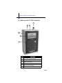
1
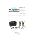
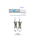
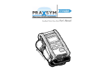
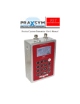
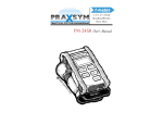
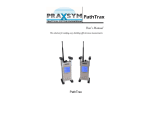
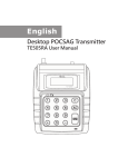
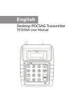
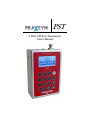
PST
2 Watt CW Test Transmitter
User’s Manual
2 WATT CW TEST TRANSMITTER
Praxsym Warranty Statement
PRAXSYM warrants that all items will be free from defects in material
and workmanship under use as specified in this guide for a period of
one year from date of delivery. PRAXSYM further agrees to repair or
replace, at its discretion, any failure which upon PRAXSYM's inspection appears to be a result of workmanship or material defect. In no
case, shall PRAXSYM's liability for breach of warranty exceed the purchase price of the items in question. PRAXSYM's liability on any claim
of any kind, for any loss connected with, or resulting from the use of,
performance or breach thereof, installation, inspection, operation or
use of any equipment furnished by PRAXSYM, shall in no case exceed
the purchase price of the goods which give rise to the claim.
www.praxsym.com
Praxsym, Inc.
P.O. Box 369
Fisher, IL 61843
Phone (217) 897-1744
Fax (217) 897-6388
[email protected]
Page i
PRAXSYM
Table of Contents
Powering The Transmitter Using the AC/DC Adapter
Keypad Definition
Page ii
2 WATT CW TEST TRANSMITTER
1.0 Introduction
1.1 Overview
The 2 Watt PST is a complete, portable CW test source capable of
transmitting test signals over the specified frequency band for
each model, listed on page 17. The output level can be adjusted
between +10 dBm and +33 dBm in 0.1 dB steps.
The transmitter frequency and output level can be set from the
touch keys on the front panel or from the touchscreen display.
The transmitter status can easily be monitored from the backlit
LCD display. The transmitter also contains a USB interface enabling the user to control the transmitter remotely.
The transmitter can be powered using the internal 6 AA rechargeable batteries for 2 hours of continuous operation at 1 W
output, or from the AC/DC wall adapter included.
1.2 Functional Description
The PST will power on to a splash screen with the Praxsym logo,
and immediately proceed to the main operation screen. The previous settings from the last use will be retained. The transmitter
will not power on transmitting RF energy, though it may have
been powered off previously while transmitting. The PST may
safely be powered off in any state using the ON/OFF button.
Never transmit without a load. Doing so may result in damage to
the PST.
Once the channel spacing is selected within the Channel Setup
menu, the step size may be adjusted from the main operation
screen. This function makes stepping across multiple channels
quick and easy during testing.
Page 1
2 WATT CW TEST TRANSMITTER
1.3 Items Supplied
E
A
D
C
B
Item
Description
A
2 Watt PST CW Transmitter
With 6 Internal NiMH AA Batteries
B
12V 5.0A AC/DC Supply
C
Power Cord
D
USB Cable
E
Flash Drive, Users Manual, Driver Software
Page 2
2 WATT CW TEST TRANSMITTER
1.4 Looking at the PST CW Transmitter
A
C
B
D
E
F
Item
Description
A
RF Output, N-Type Connector
B
Battery Charger Status LED
C
Battery Charge Jack
D
USB Port
E
LCD Touchscreen Display
F
Front Panel, Touch Keys
Page 3
PRAXSYM
2.0 Operation
2.1 Battery Charging
The PST transmitter is fully operational while the batteries are
being charged. Charging will occur whether or not the unit is
powered on.
When “batt low” appears in the battery icon, the battery life is
nearing its end. The transmitter will shut down soon. Connect
the AC/DC adapter (12 V /5.0 A) to the unit’s CHARGE jack. Plug
the adapter into a wall outlet. An internal battery charger will
control and terminate the charging of the 6 NiMH cells within
each unit. When beginning a charge cycle with batteries which
have been completely depleted, allow about two and a half
hours for a full charge to be restored. A top-off charge is recommended immediately before use for maximum battery life.
A flashing red LED indicates a pre-charge state. Usually it will
flash for a few moments and then enter a fast charge state, indicated by a solid red LED. The pre-charge state may last up to a
few hours with drained batteries and indefinitely if one or more
cells have failed. All cells must be replaced in the latter case.
When the LED turns green, the batteries are nearly full and enter
top-off mode. Continuing to charge when the LED turns green
for approximately an hour will give maximum battery life. Following top-off mode, the charger will enter trickle mode indefinitely. Fully charged batteries will give a minimum of two hours
of use at 1 W output level, and one hour at 2 W output. Also, the
battery icon on the display will be completely darkened. If the
AC/DC adapter is left connected to the PST, the charger will initiate a new charge cycle once the batteries have discharged. This
will occur continually. Unless the transmitter is in operation, it is
not recommended to leave the charger connected for more than
24 hours.
Page 4
2 WATT CW TEST TRANSMITTER
2.1 Battery Charging (Continued)
Though designed for many recharge cycles, the batteries are user
replaceable. Use only Energizer® NH15 AA NiMH rechargeable
batteries, as supplied originally. Other AA battery types such as
Alkaline or Lithium Ion may damage the transmitter. The internal
charge circuit will only work with NiMH rechargeable batteries.
Attempting to charge other AA battery types such as Alkaline or
Lithium Ion will result in damage to the transmitter.
Do not store the transmitter with discharged or failed batteries.
Discharged NiMH batteries can leak acid causing damage to the
transmitter.
2.2 Powering The Transmitter Using the AC/DC
Adapter
The PST transmitter is a battery operated portable transmitter.
However, when transmitting at 2 W, the batteries will discharge
in approximately one hour. When the AC/DC adapter is in use
while transmitting, the batteries will be charged to full capacity.
The charger will enter top-off mode, as the batteries begin to discharge. Once the battery voltage drops below the recharge
threshold, the charger will once again resume charging the batteries.
If an AC power source is available, and the PST will be transmitting at high power levels for long periods of time, the batteries
can be removed to allow the PST to use the AC/DC adapter as the
sole power source. After removing the batteries, move the short
to pins 1&2 on JP1 of the charger board. Plug the AC/DC adapter
into the charge jack and the transmitter is ready for operation. RF
performance will not change. Powering the transmitter from the
AC/DC adapter only will reduce the heat associated with the fast
charge and discharge of the NiMH batteries.
Note: Always move the short back to pins 2&3 before installing
the batteries. Failure to do so will result in damage to the batteries when a charge cycle is initiated.
Page 5
2 WATT CW TEST TRANSMITTER
2.3 Keypad Definition
ON/OFF—Turns unit on or off
Numerals 0-9—Enter a new frequency, amplitude level or step size,
select corresponding menu item choice where applicable
Numeral 1– From the main screen, pressing 1 will toggle the output between RF on and RF off.
SEL—Select. Toggles between frequency, amplitude and step size
on the main screen or chooses highlighted menu option in applicable screens.
UP/DOWN ARROWS—Adjust frequency, amplitude or step size in
the main screen by using the arrows. Adjustments to frequency
are made in the set step size. In applicable sub-menus, the arrows
control selection of menu options.
PLUS/MINUS SIGNS— Change to a positive or negative amplitude
value
LOCK/DECIMAL POINT–Locks the keypad from any unintentional
changes. Indication of lock status is on the display during the
main screen only. The keypad may be locked and unlocked from
the main operation screen only. The Decimal Point is for use
when numerically entering a new frequency, amplitude or step
size.
MENU—This brings up the Main Menu screen from the main operation screen, returns to main operation screen from Main Menu
and backtracks through menus within sub-menu screens.
Page 6
PRAXSYM
2.3 Keypad Definition (Continued)
A
C
B
D
F
Item
E
Description
A
On/Off
B
Numerals 0-9
C
Select
D
Up/Down Arrows, Plus/Minus Signs
E
Lock/Decimal
F
Menu
Page 7
2 WATT CW TEST TRANSMITTER
2.4 Display Definition
B
A
C
H
D
E
F
G
Item
Description
A
The transmitter maximum and minimum output power is displayed in the
upper right portion of the screen.
B
The transmitter maximum and minimum frequency is displayed in the
upper left portion of the screen.
C
Frequency, Amplitude, and Step size may be controlled using the SEL key
to change between the three, while the arrow keys make adjustments to
the values
D
Touch screen control of RF transmission
E
Lock status of the keypad is indicated by the padlock icon
F
Indicates setting which may be adjusted using the arrow keys
G
Battery level indicator
H
Animation will run when unit is transmitting
Note: The Battery Voltage indicator in the lower right corner of the display
shows the current battery voltage, not the remaining battery capacity.
When transmitting at 2 Watts using fully charged batteries, the display will
only be half filled due to the drop in battery voltage at high current loads.
Page 8
PRAXSYM
2.4 Display Definition (Continued)
To ensure proper care is taken of the touchscreen; avoid leaving
the screen exposed to direct sunlight for long periods of time,
clean with non-abrasive cloths (microfiber cloth), do not store in
temperatures lower than –20°C and higher than 70°C, avoid
touching the glass touchscreen with sharp or hard objects.
2.5 Menu Navigation
Pressing the MENU button from the main operation screen brings
up the Main Menu. All transmitter settings are available from this
menu. Pressing MENU again from this screen returns to the main
operation screen.
Using the arrow keys will change the highlighted menu option.
SEL chooses the highlighted menu option. Pressing the corresponding menu option on the keypad will also select menu options directly.
The Channel Setup options allow for setting of Frequency, Amplitude, and Step Size. Channel Information displaying minimum
and maximum values for frequency and RF power output are also
available.
Display Settings contains user-selectable parameters for the duration of Backlight Timeout and also Backlight Level brightness.
System Settings contains options to change Baud Rate or Disable/
Enable Transmitting when the Frequency is changed. If Disable
On New RF is ‘ON’, the PST will not transmit when a new frequency is entered. If a new step size does not require change of frequency, the PST will continue transmitting.
Pressing the MENU button while in any menu screen will backtrack through the menu hierarchy. On all screens where menu
choices may be made, an option to return directly to the main
operation screen is present.
Page 9
2 WATT CW TEST TRANSMITTER
2.6 Controlling the PST Remotely
The PST can be controlled by a PC or embedded controller via the
USB interface. Procedures in this section also describe control
with terminal emulation software on a PC or laptop computer.
Install the supplied cable between a USB port on the PC/
laptop and the USB port on the transmitter.
Start the terminal emulation software and setup with the following parameters.
Baud rate
9600, 38400, or 115200 (user selectable)
Data bits
8
Stop bits
1
Parity
none
Com port
assigned by PC operating system
Local echo
ON
Select line feed (LF) after carriage return (CR) when receiving
The settings may be found in various places depending on the
terminal emulation software used. Generally, check the Serial
Port and Terminal configuration menus.
Power up the Transmitter by depressing the ‘ON/OFF’ button.
The transmitter frequency is stored in non-volatile memory. When
power is applied to the transmitter, it will return to the last entered frequency.
Page 10
PRAXSYM
Set up the transmitter, following the recommended sequence:
Set the step size in MHz
ST=X.yyyy<CR>
Set the frequency in MHz
FR=XXXX.yyyy<CR>
Set the amplitude in dBm
AMP=+/-XX.y<CR>
Turn the RF output on
ON<CR>
See Section 3.3 for a complete listing of all error responses.
2.7 Installing the USB-Serial Driver
Plug the PST into an available USB port with the supplied
cable.
Click ‘Next
Page 11
2 WATT CW TEST TRANSMITTER
Put the supplied USB Flash Drive into the computer. Select ’Install
from a list or specific location (Advanced)’ Click ’Next’
Leave on the default setting and select ‘Include this location in
the search’ Direct the search path to the ‘FTDI VCP Drivers’ folder
located on the included USB Flash Drive. Click ‘Next’
Page 12
PRAXSYM
Click ‘Finish’
You can now go to the
‘Device Manager’ and
verify the driver was
installed successfully.
Also note the COM
number designated for
the USB drivers.
Page 13
2 WATT CW TEST TRANSMITTER
3.0 Serial Interface Operation
3.1 Configuring Tera Term Pro
Open the Terminal setup window from the Setup Menu. Select
CR+LF for Receive and CR for Transmit. Enable Local Echo. Also
within the Setup menu, choose the Serial Port option. Ensure parameters are matched to what settings were configured within
the transmitter for communication.
Tera Term must be closed and the USB cable removed before manually powering down the transmitter.
3.2 Commands
Commands may be sent in lower or upper case. <CR> represents
‘ENTER.’
SET COMMANDS
The response to successfully executed SET commands is the message OK <CR>.
FR = XXXX.yyy<CR>
Sets output frequency (in MHz). The inclusion of the decimal point
and digits to the right of the decimal are optional.
ON or OFF<CR> Enable/Disable output command. ON turns the
output on. OFF turns the output off.
AMP=+/-XX.y<CR>
Sets the output amplitude.
ST=X.yyy<CR>
Sets the channel spacing (in MHz). Example: ST=0.250 (250 kHz
Channel Spacing)
Page 14
PRAXSYM
QUERY COMMANDS
FR?<CR>
Returns the current frequency setting in the form
XXXX.yyyy (MHz).
Example: 2501.2500
MN?<CR>
Returns the lowest frequency that can be set in
the form XXXX.yyyy (in MHz).
See “FR?” for example.
MX?<CR>
Returns the highest frequency that can be set in
the form XXXX.yyyy (in MHz).
See “FR?” for example.
ST?<CR>
Returns the synthesizer step size setting in the
form X.yyyy (MHz).
Example: 0.2500
AMP?<CR>
Returns the current output amplitude in the form
+/- XX.y (dBm).
Example: +21.7
AMN?<CR>
Returns the minimum output amplitude in the
form +/- XX.y (dBm). See “AMP?” for example.
AMX?<CR>
Returns the maximum output amplitude in the
form +/- XX.y (dBm). See “AMP?” for example.
LD?<CR>
Returns “0” if the synthesizer is unlocked. Returns
“1” if the synthesizer is locked.
VR?<CR>
Returns software version of the receiver board in
the form X.yy.
Example: 3.01
VD?<CR>
Returns software version of the keypad/display
board in the form X.yy.
Example: 2.07
BV?<CR>
Returns the battery voltage level “BV=XX.y”.
Example: BV=08.0
Page 15
2 WATT CW TEST TRANSMITTER
3.3 Error Responses
Invalid commands will be acknowledged with an error response.
An error response will consist of 4 ASCII bytes followed by a carriage return. The error code consists of the two characters ER
followed by a two-character error status code.
ERIC<CR>
Invalid command
The command was not recognized because it was not in the
proper format.
ERIN<CR>
Invalid number or range
The data included in the previous command was invalid or out-ofrange.
Page 16
PRAXSYM
4.0 Specifications
4.1 Electrical Specifications
310-010129-001 (N-type)
Frequency
channel spacing
2495-2690 MHz
250 kHz, 1.00 MHz steps
Output Power
adjustable
+10 to +33 dBm
0.1 dBm
Harmonics
< -60dBc
310-010129-003 (N-type)
Frequency
channel spacing
1710-2170 MHz
30 kHz, 200kHz, 1.25 MHz steps
Output Power
adjustable
+10 to +33 dBm
0.1 dBm
Harmonics
< -60dBc
310-010129-004 (N-type)
Frequency
channel spacing
698-960 MHz
10, 12.5, 30, & 200kHz, 1.25 MHz
Output Power
adjustable
+10 to +33 dBm
0.1 dBm
Harmonics
< -50dBc
Page 17
2 WATT CW TEST TRANSMITTER
4.2 Environmental Specifications
Temp. Range:
0-50ºC
4.3 Mechanical Specifications
RF Connector:
N-type
Display:
Transflective 128x64 Black/White
White LED Backlight
Keypad:
Sixteen keys – see definition on page 3
Enclosure:
Aluminum
Power Source:
6 AA NiMH cells rechargeable
Size:
7” x 5” x 2.75” (excluding RF connector)
Weight:
4 lbs.
4.4 Shipping Settings
Baud Rate
9600
Disable On New RF
OFF
Backlight
100%
Backlight Timeout
1 minute
Page 18
PRAXSYM
Notes
Page 19
PRAXSYM
Version 052815
900-000011-002 Rev D