1
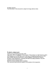
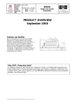
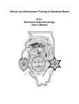
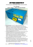
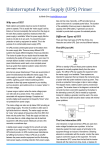
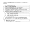
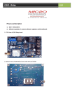
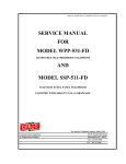
Power Quality paper #1
Causes of voltage dips & resulting problems
By: G J Coetzee
0
OVERVIEW
The smooth operation of industrial, manufacturing and mining plants (will be referred
to as a ‘plant’) are dependent on a steady power supply. Dips in the supply voltage
(depressions in supply voltage of short duration) can lead to unnecessary stoppage
of plant processes unless adequate measures have been taken in the design of the
electrical equipment.
The capital losses to a plant when process are interrupted varies significantly
depending on the type of plant. Production can be affected when normal operation
of a plant cannot be restored in a reasonable time. Further, some plants may require
capital outlay in order to restore normal operation. At some plants, the safety of
personal may be affected during the loss of operation.
In many cases, corrective measures can be taken on the electrical and control
equipment to prevent the loss of the process of a plant during voltage dips.
1
1.1
DEFINITIONS
VOLTAGE DIP WHEN DISCONNECTED FROM THE SUPPLY
A plant can be completely disconnected from its supply and be re-connected within
a few seconds. The supply voltage can be as low as zero during the time the plant
is disconnected.
1.2
VOLTAGE DIP WHILE CONNECTED TO THE SUPPLY SYSTEM
Voltage dips can occur while connected to the supply system. It is important to
distinguish between this type of voltage dip and the dips described in 1.1 above as
the performance of electrical plant during these two types of dip is different.
1.3
SYSTEMS AND SUBSYSTEMS
An industrial plant can consist of several systems, each performing a specific
function.These systems may have subsystems, serving a system. An example
would be a motor driven fan system supplying a draught to the plant process and a
lubricator-pump-subsystem supplying the bearings of the fan and/or motor.
1.4
INERTIA OF A SYSTEM
Systems or subsystems have various forms of inertia enabling them to withstand a
temporary loss of energy supplied from the electrical system before reaching a
critical stage where the process must be discontinued. As an example, a lubrication
oil pump may have a gravity fed conservator tank maintaining pressure while the
pump is temporary out of operation.
1.5
ESSENTIAL AND CRITICAL SYSTEMS
The operation of some system could be essential to maintain the plant process. Such
a system could be referred to as an ‘essential’ system from a voltage dip point of
view. However, the operation of some systems could be very sensitive to maintain
the process in the short term during supply interruptions. These are usually systems
that cannot be restarted by the operator in a reasonable time before the process must
be discontinued. These systems can be referred to as a ‘critical’ system in the plant
from a voltage dip point of view.
DIP-PROOFING
TECHNOLOGIES
INC.
DPI Binder Rev 1.0
Page 1
Power Quality paper #1
2
CAUSES OF VOLTAGE DIPS
2.1 TEMPORARY LOSS OF SUPPLY
The supply to a plant can be temporarily disconnected for a short duration and the
electrical plant can be controlled to resume operation immediately after the supply
recovers, maintaining operation of the process. Sources of this type of voltage dips
are usually Automatic Reclose (ARC) dead times and switch over from one supply
to another supply-source.
2.2
SHORT CIRCUITS
The supply voltage to a plant will dip when a short circuit occurs on the supply side
or within the plant distribution medium or low voltage system. The latter faults usually
are of concern as the depth of the voltage dip can be 100%, i.e. the supply voltage
could fall to zero. Also, the clearing times of faults on internal distribution systems are
normally longer than for faults on the supply side.
2.3
LOAD SWITCHING
Switching of load onto the supply can result in partial voltage dips. Major problems
could be experienced when large direct on line induction motors are being started.
A plant could be effected by switching taking place inside the plant or external to the
supply system.
2.4
NETWORK SWITCHING
Switching on either the supply system or the plant internal distribution network can
result in various types of voltage dips. Paralleling two supplies running at different
load angles will result in a fast transient voltage change followed by a dynamic
condition before settling at the new steady state load angle. The transient
changeover is usually fast and it is unlikely to have an effect on normal electrical
plant, unless the plant is very sensitive to voltage dips such as may be the case for
power electronic equipment.
2.5
POWER SWINGS
When the supply network is weakened by the loss of transmission lines or after
severe faults on the supply network, power swings between generating stations
lasting several seconds can occur on the network.
3
3.1
TYPICAL CHARACTERISTICS OF VOLTAGE DEPRESSIONS
SHORT CIRCUIT FOLLOWED BY A DYNAMIC CONDITION
The terminal voltage of a plant during a short circuit will depend on:
•
The impedance of the fault
•
The location of the fault
The terminal voltage, for faults of low impedance close to or at the plant, will be close
to zero. As the position of the fault moves away into a parallel supplied network, the
supplied voltage during the fault will increase.
Faults inside the distribution network of a plant will always result in a low terminal
voltage at the point of fault but may not necessarily affect the entire plant should the
fault occur at a point where the impedance between the point of fault and the point
of supply is high. Thus it is important to note that it is possible that only a part of a
Page 2
DIP-PROOFING
DPI Binder Rev 1.0
TECHNOLOGIES
INC.
Power Quality paper #1
plant may be subjected to a serious voltage dip.
1.2
11kV Board terminal voltage
1.1
Voltage (pu)
During the fault, induction motor drives will lose speed and have to re-accelerate after
the fault has cleared. On a relatively weak supply with large induction motor loads,
this current, may affect the terminal voltage as well as overload the supply system.
The current drawn by the motor during such a condition will depend on the load
torque, the inertia (rotating stored energy) of the drive, and the duration of the fault.
High inertia- drives (H > 6) after a fault of short duration (< 100 ms) will typically draw
a fraction of the starting current. As the fault duration increases, the currents drawn
by the motors will approach full starting current and the duration of the
re-acceleration currents will increase. Examples of voltage curves and starting
currents are shown in Fig 1 to Fig 6 for the system shown in Fig 7. The voltage during
the fault may not necessary remain the same as the impedance of the fault may vary.
1.0
0.9
Fault Duration:
50mS
100mS
0.8
150mS
200mS
0.0
0.2
0.4
0.6
0.8
1.0
1.2
1.4
1.6
1.8
0.7
2.0
Time
Fig 1
3.2
FAR END OF LINE TRIPPING DURING FAULT
DIP-PROOFING
TECHNOLOGIES
INC.
DPI Binder Rev 1.0
Page 3
1.2
11kV Board terminal voltage
1.1
Voltage (pu)
Power Quality paper #1
1.0
0.9
Fault Duration:
200mS
250mS
0.8
300mS
350mS
0.0
0.2
0.4
0.6
0.8
1.0
1.2
1.4
1.6
1.8
0.7
2.0
Time
1.2
11kV Board terminal voltage
1.1
Voltage (pu)
Fig 2
1.0
0.9
Fault Duration:
50mS
100mS
0.8
150mS
200mS
0.0
0.2
0.4
0.6
0.8
1.0
1.2
1.4
1.6
1.8
0.7
2.0
Time
Fig 3
Page 4
DIP-PROOFING
DPI Binder Rev 1.0
TECHNOLOGIES
INC.
Power Quality paper #1
25
MVA
MVA drawn by 11kV feeder
20
15
Fault Duration:
50mS
10
100mS
150mS
200mS
0.0
0.2
0.4
0.6
0.8
1.0
1.2
1.4
1.6
5
0
2.0
1.8
Time
Fig 4
25
MVA
MVA drawn by 11kV feeder
20
15
Fault Duration:
200mS
10
250mS
300mS
350mS
0.0
0.2
0.4
0.6
0.8
1.0
1.2
1.4
1.6
1.8
5
0
2.0
Time
Fig 5
DIP-PROOFING
TECHNOLOGIES
INC.
DPI Binder Rev 1.0
Page 5
Power Quality paper #1
25
MVA
MVA drawn by 11kV feeder
20
15
Fault Duration:
350mS
10
400mS
450mS
500mS
0.0
0.2
0.4
0.6
0.8
1.0
1.2
1.4
1.6
1.8
5
0
2.0
Time
Fig 6
Infinite busbar
XFL = 0.002 pu
(Supply fault level)
11kV Busbar
XTRFR = 0.04 pu
(Impedance of Trfr)
525V Busbar
6 off 270kw Motors
with H = 0.4sec
All impedances are at 525V & 6 x 270kw base
Fig 7
Case study network details
Page 6
DIP-PROOFING
DPI Binder Rev 1.0
TECHNOLOGIES
INC.
Power Quality paper #1
When a fault occurs on one of several parallel feeders supplying a plant, the time at
which the fault clears on the plant side of the line, and on the far end of the line, could
be different. Fig 8 shows a typical example of the terminal
voltage where the
far end of the line opens after the plant side, for a fault near the plant.
Voltage (pu)
1 pu
3.3
Re-acceleration of motors
Breaker opening at far end of line
Breaker opening at plant side
Time
Fig 8
Voltage during a severe short circuit close to the point of supply and cleared by
line protection.
BACK GENERATION OF MOTORS
When the supply to a plant is disconnected, the motors will back-generate and the
voltage will not instantaneously fall to zero. Motors with low inertias and high load
torques can stall within 150 ms and the back generated voltage will decay quickly due
to the rapid decay in shaft speed. On a plant where one or more large motors with
high inertias operates (such as fans) the terminal voltage will decay with a time
constant as long as 1.5 seconds. This slow decay in voltage will reduce the
deceleration of other small inertia low load torque motors connected to the same
busbar.
3.4
LOSS OF SUPPLY DUE TO ARC DEAD TIME
The dead time for a three phase automatic reclosure (ARC) network is normally
within 3 to 5 seconds. For a single phase trip, which is a partial loss of supply, the
ARC dead time is set as low a 1 second.
3.5
UNBALANCE OF SUPPLY
The magnitude of unbalance in the three phase supply voltage is as important as the
magnitude of a voltage dip. The torque of a three phase induction motor drive is
dependant on the positive phase sequence component of the supply voltage. The
presence of negative phase sequence components in the supply voltage will reduce
the motor applied torque. It is thus important that any form of busbar voltage condition
monitoring relay should not only sense the magnitude of the voltages, but also sense
the negative phase sequence component. Such a relay will verify that the supply
voltage is adequate to drive three phase motors: A high negative phase sequence
component can be present on the supply voltage, depending on the network
configuration, during the dead time of a single phase ARC.
3.6
POWER SWINGS
During a large power swing on the network, the terminal voltage at a plant can
oscillate at a frequency between 0.1 and 2 Hz with minimum values as low as 65 %.
Such power swings normally last only for a few seconds but under severe weak
interconnected network conditions, the oscillations may continue for several tens of
seconds. The electrical equipment of an industrial plant, if correctly designed, can
DIP-PROOFING
TECHNOLOGIES
INC.
DPI Binder Rev 1.0
Page 7
Power Quality paper #1
continue operation during such voltage dips. This type of voltage dip is unlikely to
occur on an industrial plant which is supplied from a strong point in the national
network.
3.7
SWITCHING OF LOADS
Voltage dips can be generated on a plant supplied by a relatively weak network,
when large direct on-line induction motors are started. The duration of these voltage
dips is dependant on the starting time of the motors.
4
4.1
EFFECTS OF VOLTAGE DIPS ON INDUSTRIAL PLANT
IMPACT ON THE PROCESS
When a voltage dip occurs on the supply of an industrial plant, various parts of the
plant process will rapidly approach a point where the process must be discontinued
in order to safeguard the plant. It is essential to know the time it takes from the
initiation of the voltage dip to the time when the process must be discontinued for a
plant, before any counter measures can be designed. It is also important to arrange
the electrical supply equipment in such a manner that its outage time is minimized
following a voltage dip. Unsuccessful ARC of transmission lines can result in a
second voltage dip. It is thus important to restore the plant process as soon as
possible after voltage restoration.
4.2
DROPOUT OF CONTACTORS
A common problem with Low Voltage (LV) switchgear is that the electrically held in
contactors fall out during voltage dips. The supply controlling the contactors is normally taken directly from the associated busbar supply voltage. When the control
voltage falls below 70% of its nominal value, the contactor may open and the seal-in
contact will open. LV drives may thus stop when a voltage dip occurs.
4.3
VARIABLE SPEED DRIVES
Smooth operation of Variable Speed Drives (VSD) following a voltage dip is not
possible on all types of VSD’s. The operation of firing circuits controlling power
electronics such as thyristors cannot be maintained when the voltage falls to a low
level and the drive must be stopped. On some types of VSDs it is possible to turn the
firing of thyristors off immediately when a large voltage dip is detected and then
carefully start the firing once the supply voltage has recovered.
Careful consideration should thus be given when selecting VSDs which will drive
loads essential to maintain the plant process. The control of VSDs during small
voltage dips of long duration should also be taken into account when selecting VSDs.
4.4
CONTROL EQUIPMENT SUPPLIES
The application of control equipment such as Programmable Logic Controllers (PLC)
in plants is very common. However, this type of control equipment requires a standby
supply. Care should be taken that the supply to such equipment is secure against
voltage dips. Alternatively, the outputs of a PLC can be switched off in the event of
a voltage dip of a magnitude and duration which can damage plant or the process.
4.5
PROTECTION
The setting of protection relays plays a major role in the smooth operation of a plant
during voltage dips. The incomer, transformer, MV switchgear and motor protection
relay settings must be correctly set in a coordinated manner.
Page 8
DIP-PROOFING
DPI Binder Rev 1.0
TECHNOLOGIES
INC.
Power Quality paper #1
The following points are of importance:
The co-ordination of electrical protection relay settings with the dynamic currents
which will flow when the voltage recovers after a voltage dip must be taken into
account.
The settings of all under voltage relays and their associated timers on the entire plant
should be coordinated to make maximum plant available during a voltage dip without
exceeding the capability of the equipment.
In many instances a sub contractor supplies a sub-system with its associated
protection incorporated in his scope of supply. It should be verified that all under
voltage protection relay settings are consistent throughout the plant.
Often protection equipment is set to trip for a condition without any time delay. An
example would be a lubrication oil pressure sensor tripping a system immediately
when the pressure falls below a preset value. It may be within the capability of the
plant to operate for a few seconds at a low pressure without damaging the plant. By
introducing time delays on protection trip signals with discretion, the operating range
of the plant can be increased to allow short interruptions.
5
CONCLUSIONS
Any electrical system is vulnerable to short circuits, although some more than others,
which will lead to voltage dips.
If the effect of voltage dips is taken into consideration during the design phase of a
plant, the best method can be implemented to ensure the smooth running of a plant.
This is not always considered during the design phase of the plant and action is taken
only when the problem reveals itself during the commissioning phase.
A great deal of information on the supply system and the plant process is required
before decisions can be made on appropriate counter measures to avoid loss of
production during voltage dips.
Paper: Causes of voltage dips & resulting problems
By: G J Coetzee - Senior Consultant, Eskom MW Park, Generation Technology
Department, PO Box 1092, Johannesburg, 2000
DIP-PROOFING
TECHNOLOGIES
INC.
DPI Binder Rev 1.0
Page 9