1
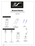
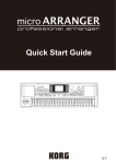
Ozone Systems
I nstallati o n & Mai ntenance Manual
PR-1300
Ultraviolet Ozone Generator
ClearWater Tech, LLC.
Integrated Ozone Systems
850-E Capitolio Way, San Luis Obispo, Ca 93401 • 805-549-9724 • Fax: 805-549-0306 • E-mail: [email protected] • www.cwtozone.com
Copyright © 2009 - ClearWater Tech, LLC • Reproduction of any kind is prohibited • LIT90 • REV52709
IMPORTANT SAFETY INSTRUCTIONS
When installing and using this electrical equipment, basic safety precautions should
always be followed, including the following:
1)
2)
3)
4)
Read and follow all instructions.
Save these instructions.
Al way s be s ur e t he unit is unpl ugged duri ng i nst all ati on or ser vice
pr ocedur es.
The ult r avi ol et li ght pr oduced by t he U V l am ps is har mful t o y our
ey es. Do not l ook dir ectly at the l am ps. S hould i t becom e necessary
to vi ew t he l amps, us e U V- pr ot ected s afet y gl ass es.
5)
All electrical connections should be made by a licensed or qualified electrician.
6)
Before attempting any electrical connections, be sure all power is off at the main circuit breaker.
7)
Install the ozone generator at least five feet from the tub water using non-metallic plumbing.
8)
Install the ozone generator no less than one foot above the maximum water level to prevent water from
contacting the electrical equipment.
9)
The electrical supply for this product must include a suitable rated switch or circuit breaker to open all
ungrounded supply conductors to comply with Section 422-20 of the National Electrical Code,
ANSI / NFPA 70-2008. The disconnecting means must be readily accessible to the occupant, but
installed at least five feet from the tub water.
2
PRODUCT DESCRIPTION
We recommend that you become familiar with the PR-1300 unit by studying this illustration. All components will be
referred to by the names below:
Air Supply
Power Supply
To UV Lamp
Mounting Bracket
UV Lamp
Holder
Reaction Chamber
Retaining Clip
And Screws
Indicator Light
Reaction Chamber
24 Hour Timer
Mounting Bracket
Ozone Outlet
Fitting
Grounded Electrical Cord
Grounding Lug
3
PLUMBING
There are two ways to plumb the PR-1300:
1.
2.
Using a tee in the air venturi line.
Using a di f fuser stone.
NOTE: All fittings, with the exception o f a tee, will be provided by ClearWater Tech.
AIR LINE - TEE INSTALLATION:
NOTE : Use the following instructions i f the venturi or air line o f the spa is accessible. The air line is the upper PVC
pipe, flex or rigid, o f the jet fittings. I f the venturi line is not accessible, the instructions for the dif fuser stone should be
followed.
For air line tee installation locations, see the installation schematic #T1 & #T2.
1.
Mount the PR-1300 using the four mounting brackets. The system is intended to be mounted five feet from the spa
or at the remote power pack site.
2
Determine the size of the venturi line, either 1/2", 3/4" or 1 1/2". Purchase a PVC tee the same size as your line, with
a 1/2" female threaded top.
3.
Turn the spa on high speed (blower not necessary). By having the spa on, water will evacuate this line. If
your selected plumbing location is in an area over the power pack, we recommend draining the spa.
4.
Cut the PVC pipe between the two lowest jets (if possible), this will give you the longest contact time. If the
low jets are not accessible, any location on this line will work.
5.
Cement the tee in place with the 1/2" threads opening up.
6.
Using Teflon tape, screw the provided tube fitting into 1/2" threads in the tee. Install one end of the ozone
delivery line on the tube fitting.
7.
Run the delivery line up from the tee to the highest point possible and cut the line here to install the check
valve. (See illustrations on installation schematic) NOTE: THE CHECK VALVE SHOULD BE MOUNTED
ABOVE THE WATER LINE. BE SURE THE FREE FLOW IS TOWARDS THE ELBOW OR AWAY FROM
THE OZONE UNIT.
8.
Continue running the delivery line back down and out to the ozone generator.
DIFFUSER STONE APPLICATION
1.
The diffuser stone is already connected to the end of the ozone tubing supplied by ClearWater Tech.
2.
Simply attach the open end of the tubing to the fitting at the bottom of the PR-1300, and drop the diffuser stone into the
spa. When the ozonator is operating you should see tiny bubbles being dispersed from the diffuser stone.
NOTE: FOR OPTIMAL RESULTS, USE THE DIFFUSER STONE SIMULTANEOUSLY WITH THE FILTRATION CYCLE.
NOTE: DIFFUSER STONES MAY BECOME CLOGGED AND RESULT IN AIR COMPRESSOR DAMAGE. TO PREVENT THIS
FROM HAPPENING, IT IS RECOMMENDED TO CLEAN YOUR DIFFUSER STONE ONCE A MONTH. THIS CAN BE DONE BY
SUBMERSING THE DIFFUSER STONE FOR A FEW HOURS IN A SOLUTION MADE OF 50% WATER AND 50% MURIATIC
ACID.
4
INSTALLATION SCHEMATIC
Air Control Valve
Check Valve mounted ABOVE the water level
(Must remain closed on air line installation)
Location T1
Spa Air Line
Location T2
Location IM 2
Water Line
Location IM 1
Ozone Delivery Line
5
ELECTRICAL WIRING:
Models with cords simply need to be plugged into a grounded 110V wall outlet. An overcurrent protector must be provided by
connecting to a branch circuit rated at 20 AMPS or less. NOTE: ALL LOCAL ELECTRICAL CODES MUST BE OBSERVED.
GFI (GROUND FAULT INTERRUPTER)
1.
To test the GFI push the black TEST button. Red RESET button should pop out from inner surface. This should result in power
being OFF at all outlets protected by the GFI. NOTE: If RESET button does not pop out DO NOT USE THIS
ELECTRICAL APPLIANCE. CALL A QUALIFIED ELECTRICIAN.
2.
If the GFI tests okay, restore power by pushing the RESET button in. The RESET button must be pushed firmly and fully into
place until it locks and remains depressed after pressure has been removed. IF THE GFI FAILS TO RESET
PROPERLY, DO NOT USE - CALL A QUALIFIED ELECTRICIAN.
3.
If GFI trips by itself at any time during or after installation, RESET it and perform test procedures 1 and 2 above. IF RESET
BUTTON DOES NOT POP OUT WHEN TEST BUTTON IS DEPRESSED, DO NOT USE GFI. CALL A QUALIFIED
ELECTRICIAN. NOTE: THE GFI SHOULD BE TESTED AT LEAST ONCE A MONTH.
O PE RAT I O N
After the installation has been completed, the spa will operate as before. Again, for best results run the timer of your PR-1300 simultaneously with the filtration cycle.
NOTE: If your PR-1300 is installed to your air line, it is important to remember to keep the air dial(s) closed when not using the spa.
The indicator light on the PR-1300 will be on if the unit is working, and you should smell a slight odor of ozone from the spa.
RUNNING TIME:
We suggest you start out with 4 hours of total running time. It is best to split this time up into at least two two-hour intervals; or four
one-hour intervals. We recommend you start with the longer periods and work your way down until you find the optimum running
time for your application.
Examples:
10-12 AM
or
12-1 AM and 12-1 PM
10-12 PM
or
6-7 AM and 6-7 PM
The bather load and frequency of use will differ from owner to owner, therefore, you can adjust the time to fit your own needs by
increasing or decreasing the hours on your time clock. NOTE: On commercial systems the filtration time will need to be increased.
Please consult your dealer.
6
PROGRAMMING INSTRUCTIONS:
To Set or Change the Time: To clear entire memory, press reset key. Hold down the CLOCK key while pressing either
the HOUR or MINUTE keys. Continue pressing until the desired number is shown. Then simply lift finger off the
CLOCK key to set.
To Set program (On/Off Times): Press TIMER key once to enter into program mode. Display will show "1 ON - - - -".
Press the HOUR key and then the MINUTE key to select the desired first ON time. Press TIMER key once. Display will
show "1 OFF - - - -". Repeat previous step to select the desired first OFF time. Repeat the entire sequence to complete up
to eight ON/OFF times as desired. When programming is done, press the CLOCK key then the SELECT key repeatedly
until the indicator bar is above the word "AUTO".
To Review Program: Press TIMER key repeatedly. When done, press the CLOCK key to return to the time of day.
To Cancel/Change Part of the Program: Press TIMER key repeatedly until the particular ON or OFF time appears. Set
new ON or OFF time. (See: to set programs)
To Override Automatic Operation: Press the SELECT key to move indicator bar to the desired ON or OFF position.
Note: Timer will not resume automatic operation until indicator bar is repositioned above the word AUTO.
To Override Timer Status (On or OFF): Press "OVR", key. Timer will resume automatic operation with the next
opposite set point.
7
U N DE RST AN DIN G YO U R W AT E R
If you are aware of a high concentration of any mineral in your water (like calcium or iron), it is necessary to treat your water
before starting the PR-1300 system. We suggest you take a sample of your water to a qualified pool and spa dealer for analysis.
They will make the proper recommendations of product(s) needed to remove these minerals from your water. You should only have
to do this when you drain and fill new water into the spa.
If your water is clean and clear, you can start the PR-1300 system right away. If the water is dirty or cloudy, we recommend that
you drain the water and thoroughly clean the filter(s) first.
CAUTION: It is not recommended that you drain an in-ground spa in the winter or after the first rain of the season. Instead, you
should use a shock treatment because by draining you could possibly float the spa out of the ground resulting in severe damage.
O ZO N E AN D BRO MIN E or CH LO RIN E
Ozone has a short half-life, or residual time, in your water. So there is a need to maintain a small residual of another product in the
spa or pool. We recommend that you use Bromine. This Bromine residual will act as a buffer when the ozone system is not operating.
The bromine needs to be maintained at ONLY 0.8 ppm (parts per million), so that the trace amount of product in the water will
not be noticed. Chlorine will work as a residual oxidizer, and may be used effectively in conjunction with the ozone system.
Prepare your Water
You should prepare your water by making the following adjustments and maintain these levels while using the PR-1300 system:
Bromine
1 to 8 ppm
Chlorine
1 to .5 ppm
PH
7.2-7.6
Total Alkalinity
80-150 ppm
Calcium Hardness
180-250
Note: If you experience any reaction with your water, such as coloring or unusual odor, please wait a few days to give the ozone and
filter system time to work. If the situation continues, consult your pool and spa dealer, possibly taking them a sample of the water.
S HO CK T RE AT ME NT
If the water becomes cloudy with excessive oils or other contaminates, or after an unusually high bather load, we recommend that
you use a Non-chlorine shock treatment to assist the ozone in cleaning the water. These Non-chlorine shock treatments are
available at your local pool or spa supply dealer, and are marketed under several different brand names, ask for assistance in
selecting the proper product.
FILT E R CLE AN ING
Ozone will keep your spa much cleaner than any other type of spa or pool purification system. The reason is that ozone neutralizes body
oils and soaps. After ozone kills the bacteria, the end product is oxygen, carbon dioxide and filterable solids. The filterable solids are
usually at a higher level than with conventional sterilization processes, so your filter has a bit more work to do. Keeping the filter clean
will make a definite difference in the clarity of the water. Please set up a regular cleaning program, or the end result will be poor flow
when the low speed of the pump comes on with the ozone system. This will have a direct effect on the amount of ozone that will get into
the water. An easy check you can do without removing the filter is to look for air bubbles through the jets (on air line installations) when
the spa system is on low speed (usually controlled by the timer). When the filter is clean you will see many bubbles, when it is dirty you
will hardly see any bubbles.
8
MAINTENANCE
Caution: Never look at the unshielded ozone lamp while operating the unit. This lamp can cause severe eye and skin damage. There
is an indicator light which will turn blue in color when the unit is operating. See product description for location of the indicator light.
Lam p
The PR-1300 lamp has an 9,000 hour life expectancy. That's about 5 years of life, running 4 hours per day, as recommended. On
commercial installations we recommend replacing the lamp every 12 to 18 months.
Repl aci ng t he Lam p
Lamps are available from your ClearWater Tech dealer should it need to be replaced. Disconnect the power to the unit and remove the
front cover retaining thumbscrew and front cover. Using a 9/64” Allen wrench, remove the two screws holding the reaction chamber
retaining clip in place and remove the clip. (See the illustration at the beginning of this manual.) Disconnect the plug on the end of the
ozone lamp and pull the top end of the reaction chamber up and out so that the ozone outlet fitting on the other end pulls free of its hole
in the enclosure. Once the chamber is free of the enclosure, loosen the lamp holder locking ring from around the top end of the lamp by
turning it counterclockwise and remove it. (See illustration below.) Remove lamp by grasping the rubber bushing around the end of the
lamp and pulling it straight out. Remove the rubber bushing from the lamp and install it on your new lamp making sure the outer edge
of the bushing is flush with the outer edge of the silver end cap on the lamp. Now, slide the lamp back into the reaction chamber.
Caution: Keep lamp free of fingerprints and dust particles by only handling the end caps on the lamp. You can clean the lamp with
rubbing alcohol and a soft cloth. A dirty lamp will not allow maximum ozone output. IMPORTANT! There is a
centering device inside at the other end of the chamber. Care must be taken to make sure the lamp is inserted into the hole in the
centering device before the lamp holder is tightened. The lamp holder may now be reinstalled and tightened. Reinsert the reaction
chamber into the enclosure and reconnect the plug onto the lamp. Reinstall the retaining clip and screws and the front cover and
thumbscrew. Reconnect power to the unit device inside at the other end of the chamber.
Rubber Bushing
Ozone Lamp
(Pt # LA20)
Electrical Plug
Lamp holder
locking Ring
(2 pieces)
9
Air Inlet
Handle Ozone Lamp
by end cap,
not by glass
Ozone Cell
TROUBLE SHOOTING
SITUATION: No indicator light
1.
Check GFI to see if it has tripped.
2.
Check lamp connection.
3.
Check for blown lamp.
4.
Check power supply.
SITUATION: Ozone not present in water
1.
Check for clean filter (a dirty filter will cause a low flow of ozone to spa).
2.
Make sure air dial is closed on air line installations.
3.
Make sure adjustable jets are all open and not loose.
4.
Check for clogged jet (debris in line).
5.
Check for kinked delivery line, blocked or reversed check valve.
6.
Check diffuser stone to see that it has not been fouled.
SITUATION: Cloudy water with ozone present
1.
Check pH balance.
2.
Clean filter.
3.
Check for other minerals in water.
4.
Use a spa shock treatment to rid water of excess body oils.
5.
Drain and clean spa and filtd thoroughly.
P R- 1300 S PE CIFICAT IO NS
Energy required: 115 VAC 0.6 AMPS, 65 watts
Rated up to: 1000 gallon spa or 2000 gallon pool
Average lamp life: 8500 hours
Compressor rating: 6 PSI
Size: 20" x 8 3/4" x 3 1/2"
Shipping Weight: 20 lbs.
10
ClearWater Tech, LL C L i mi t ed One-Year War ran ty
Summary of the Warranty
ClearWater Tech, LLC (“CWT”) makes every effort to assure that its products meet high quality and durability standards and warrants the products it manufactures
against defects in materials and workmanship for a period of one (1) year, commencing on the date of original shipment from CWT, with the following exceptions: 1)
The warranty period shall begin on the installation date if the installation is performed within 90 days of the original shipment from CWT; 2) The warranty period shall
begin on the date of the bill of sale to the end user if the installation date is more 90 days after the original shipment date. To validate the warranty, a warranty card,
accompanied by a copy of the bill of sale, must be returned to CWT and must include the following information:
• End user name
• Complete address, including telephone number
• Date installed • Complete model and serial number information
• Name of company from which the unit was purchased
Repairs and replacement parts provided under this warranty shall carry only the unexpired portion of this warranty or 90 days, whichever is longer.
Items Excluded from the Warranty
This warranty does not extend to any product and/or part from which the factory assigned serial number has been removed or which has been damaged or rendered
defective as a result of:
• an accident, misuse, alteration or abuse
• an act of God such as flood, earthquake, hurricane, lightning or other disaster resulting only from the forces of nature
• normal wear and tear
• operation outside the usage parameters stated in the product user’s manual
• check valve/solenoid valve failure
• use of parts not sold by CWT
• damage which may occur during shipping
• service or unit modification not authorized by CWT
• failure to meet service requirements as outlined in the I & O manual
Obtaining Service Under the Warranty
Any product and/or part not performing satisfactorily may be returned to CWT for evaluation. A Return Goods Authorization (RGA) number must first
be obtained by either calling or writing your local authorized dealer, distributor or CWT direct, prior to shipping the product. The problem experienced
with the product and/or part must be clearly described. The RGA number must appear prominently on the exterior of the shipped box(es). The product
and/or part must be packaged either in its original packing material or in comparable and suitable packing material, if the original is not available. You
are responsible for paying shipping charges to CWT and for any damages to the product and/or part that may occur during shipment. It is recommended
that you insure the shipment for the amount you originally paid for the product and/or part.
If, after the product and/or part is returned prepaid and evaluated by CWT, it proves to be defective while under warranty, CWT will, at its election,
either repair or replace the defective product and/or part and will return ship at lowest cost transportation prepaid to you except for shipments going
outside the 50 states of the United States of America. If upon inspection, it is determined that there is no defect or that the damage to the product
and/or part resulted from causes not within the scope of this limited warranty, then you must bear the cost of repair or replacement of damaged product
and/or part and all return freight charges. Any unauthorized attempt by the end user to repair CWT manufactured products without prior permission
shall void any and all warranties. For service, contact your authorized dealer or distributor or CWT direct at (805) 549-9724, extension 23.
Exclusive Warranty
There is no other expressed warranty on CWT products and/or parts. Neither this warranty, or any other warranty, expressed or implied, including any
implied warranties or merchantability of fitness, shall extend beyond the warranty period. Some states do not allow limitations on how long an implied
warranty lasts, so that the above limitation or exclusion may not apply to you.
Disclaimer of Incidental and Consequential Damages
No responsibility is assumed for any incidental or consequential damages; this includes any damage to another product or products resulting from such a defect. Some
states do not allow the exclusion or limitation of incidental or consequential damages, so that above limitation or exclusion may not apply to you.
Legal Remedies of Purchaser
This warranty gives you specific legal rights and you may also have other rights which vary from state to state.
THIS STATEMENT OF WARRANTY SUPERSEDES ALL OTHERS PROVIDED TO YOU AT ANY PRIOR TIME.
C learWater Tech, L LC .
850 Capitolio Way, Suite E, San Luis Obispo, California 93401 • (805) 549-9724 • Fax: (805) 549-0306
11