1
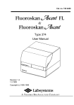
Fluoroskan Ascent®
Fluoroskan Ascent® FL & Fluoroskan Ascent®
User Manual
User Manual Rev. 2.4; Nov. 2008, Cat. no. 1506450
2
Fluoroskan Ascent® FL & Fluoroskan Ascent® User Manual
Table of Contents
Symbols and Markings ................................................................. 7
1.
Introduction............................................................................ 9
2.
Instrument Layout ................................................................ 13
3.
Installation ........................................................................... 19
4.
Operation ............................................................................. 31
5.
Maintenance ......................................................................... 61
6.
Troubleshooting Guide ......................................................... 71
7.
Frequently asked questions (FAQ) about the Fluoroskan
Ascent FL and Fluoroskan Ascent ........................................ 75
8.
Instrument Service ............................................................... 81
9.
Disposal of the Instrument and Materials ............................ 87
10. Ordering Information ........................................................... 89
11. Glossary and Abbreviations ............................................... 101
12. Literature ........................................................................... 105
13. Warranty Certificate........................................................... 107
14. Specifications .................................................................... 109
15. Index .................................................................................. 115
Appendix A. Brief User’s Guide ................................................ 119
Appendix B. Filter Order Form.................................................. 121
Appendix C. Addresses ............................................................ 123
Fluoroskan Ascent® FL & Fluoroskan Ascent® User Manual
3
Contents
Symbols and Markings..................................................................7
1.
Introduction .........................................................................9
1.1
Intended use .................................................................................... 10
1.2
Method descriptions ....................................................................... 11
1.2.1
Fluorometric measurement principle...................................... 11
1.2.2
Luminometric measurement principle (Fluoroskan Ascent FL)
11
2.
Instrument Layout .............................................................13
2.1
2.2
2.3
2.4
2.5
2.6
2.7
2.8
2.9
3.
Front view ........................................................................................ 13
Rear view ......................................................................................... 14
Internal view .................................................................................... 15
Optical system ................................................................................. 16
Control switches.............................................................................. 16
Incubator.......................................................................................... 17
Excitation beam selector................................................................. 17
Dispensers ....................................................................................... 17
Plate carrier...................................................................................... 18
Installation .........................................................................19
3.1
Upon delivery .................................................................................. 19
3.1.1
Unpacking................................................................................. 19
3.1.2
Checking delivery for completeness....................................... 20
3.1.3
Checking for damage during transport................................... 20
3.1.4
Environmental requirements and noise.................................. 21
3.1.5
Things to avoid......................................................................... 21
3.1.6
Technical prerequisites............................................................ 22
3.2
Releasing the transportation lock ................................................... 22
3.3
Power and computer connections ................................................. 23
3.4
Installation of dispensers ................................................................ 25
3.5
Installation of the drop plate ........................................................... 26
3.6
Plate adapters .................................................................................. 27
3.7
Adjusting the plate carrier............................................................... 29
3.8
Operational check............................................................................ 30
4.
Operation ...........................................................................31
4.1
4
Switching on.................................................................................... 31
Fluoroskan Ascent® FL & Fluoroskan Ascent® User Manual
4.2
Loading the microplate ................................................................... 32
4.3
Fluorometric measurement ............................................................ 33
4.3.1
Validation.................................................................................. 34
4.3.2
Scaling ...................................................................................... 35
4.3.3
Dynamic series test solutions ................................................. 36
4.4
Luminometric measurement .......................................................... 37
4.4.1
Luminometric scaling .............................................................. 38
4.5
Other functions................................................................................ 39
4.5.1
Orbital shaking ......................................................................... 39
4.5.2
Incubator .................................................................................. 42
4.5.3
Dispensers................................................................................ 42
4.5.4
Dispenser head height adjustment ......................................... 45
4.5.5
Chemical resistance of the dispenser ..................................... 47
4.5.6
Excitation light beam selector................................................. 50
4.5.7
Area measurements ................................................................ 51
4.6
Changing the measurement direction ........................................... 51
4.7
Installing or removing the light shield ........................................... 54
4.8
Installing the filters .......................................................................... 56
4.9
Shutdown ........................................................................................ 59
5.
Maintenance...................................................................... 61
5.1
Routine cleaning of the instrument ................................................ 61
5.2
Cleaning the optical system ........................................................... 62
5.2.1
Visual filter check ..................................................................... 62
5.3
Cleaning the plate carrier................................................................ 63
5.4
Replacing the halogen lamp ........................................................... 64
5.5
Routine maintenance of optional dispensers and main lens........ 65
5.5.1
Basic maintenance ................................................................... 65
5.5.2
Extended maintenance ............................................................ 65
5.5.2.1
5.5.2.2
5.5.2.3
Weak detergent or 10% bleach ..................................................... 65
Weak acid and base in sequence................................................... 66
Cleaning the main lens................................................................... 66
5.6
Periodic maintenance ..................................................................... 66
5.6.1
Replacing the dispenser tubings............................................. 67
5.6.2
Replacing the dispensing tip ................................................... 69
5.6.3
Replacing the dispenser syringe............................................. 70
6.
Troubleshooting Guide ...................................................... 71
6.1
6.2
Troubleshooting.............................................................................. 71
Error messages ............................................................................... 74
Fluoroskan Ascent® FL & Fluoroskan Ascent® User Manual
5
7.
Frequently asked questions (FAQ) about the Fluoroskan
Ascent FL and Fluoroskan Ascent...............................................75
8.
Instrument Service.............................................................81
8.1
8.2
8.3
8.4
8.5
9.
Service request protocol................................................................. 81
Decontamination procedure ........................................................... 81
Certificate of decontamination ....................................................... 83
Shipping the instrument (or items) ................................................ 85
Service contracts............................................................................. 85
Disposal of the Instrument and Materials..........................87
9.1
9.2
10.
10.1
10.2
10.3
10.4
Disposal of the instrument.............................................................. 87
Disposal of materials....................................................................... 87
Ordering Information .........................................................89
Product code numbers ................................................................ 89
List of recommended spare parts............................................... 96
Ordering filters ............................................................................. 96
Fluorochromes and corresponding filter pairs .......................... 99
11.
Glossary and Abbreviations .............................................101
12.
Literature .........................................................................105
13.
Warranty Certificate ........................................................107
13.1
14.
14.1
14.2
14.3
14.4
15.
Warranty limitations .................................................................. 108
Specifications ..................................................................109
General specifications ............................................................... 109
Safety specifications.................................................................. 111
In conformity with the requirements ........................................ 112
Performance specifications ....................................................... 113
Index ................................................................................115
Appendix A. Brief User’s Guide ................................................119
Appendix B. Filter Order Form ..................................................121
Appendix C. Addresses .............................................................123
6
Fluoroskan Ascent® FL & Fluoroskan Ascent® User Manual
Symbols and Markings
SYMBOLS USED IN THE FLUOROSKAN ASCENT FL AND FLUOROSKAN ASCENT
Power ON
Power OFF
Connection to the protective grounding system
WARNING MARKINGS USED ON THE INSTRUMENT
Caution: risk of electric shock.
Caution: risk of personal injury to the operator or a
safety hazard to the surrounding area. See the
accompanying documentation.
CE compliance mark
WEEE symbol This product is required to comply with
the European Union’s Waste Electrical & Electronic
Equipment (WEEE) Directive 2002/96/EC.
WARNING MARKINGS USED IN THE DOCUMENTATION
Caution: risk of electric shock.
Caution: risk of personal injury to the operator or a
safety hazard to the surrounding area.
Caution: risk of serious damage to the instrument, other
equipment or loss of performance or function in a
specific application.
Caution: biohazard risk.
Fluoroskan Ascent® FL & Fluoroskan Ascent® User Manual
7
Fluoroskan Ascent, Cat. no. 5210470 and 5210480 (with dispenser)
Fluoroskan Ascent FL, Cat. no. 5210450 and 5210460 (with dispenser)
User Manual Rev. 2.4; Nov. 2008, Cat. no. 1506450
Copyright
© 2008 Thermo Fisher Scientific Corporation. All rights reserved. First edition
published in 1995. Reproduction of the accompanying user documentation in
whole or in part is prohibited.
Patents
The Fluoroskan Ascent FL and Fluoroskan Ascent have national and international
patents and patents pending.
Trademarks (® and ™)
Ascent Software, Fluoroskan, Fluoroskan Ascent, Immulon, Luminoskan,
Luminoskan Ascent, Microfluor and Microtiter are registered trademarks of Thermo
Fisher Scientific. BioBind and Microlite are trademarks of Thermo Fisher Scientific.
alamarBlue is a trademark of AccuMed International, Inc.
AlexaFluor, PicoGreen and Texas Red are registered trademarks of Molecular
Probes.
OliGreen and RiboGreen are trademarks of Molecular Probes.
AttoPhos is a trademark of JBL Scientific.
Cy is a trademark of Amersham Biosciences.
StarBright Green is a trademark of Chromagen.
Virkon is a registered trademark of Antec International Ltd.
All other trademarks, registered trademarks and copyrights are the property of
their respective holders.
Disclaimer
Thermo Fisher Scientific reserves the right to change its products and services at
any time to incorporate technological developments. This manual is subject to
change without prior notice. Although this manual has been prepared with every
precaution to ensure accuracy, Thermo Fisher Scientific assumes no liability for
any errors or omissions, nor for any damages resulting from the application or use
of this information. This manual supersedes all previous editions.
No liability for consequential damages
Thermo Fisher Scientific shall not be liable for any damages whatsoever arising out
of the use or inability to use this product.
Contact information
Thermo Fisher Scientific Oy
Microplate Instrumentation
Ratastie 2, P.O. Box 100, FI-01621 Vantaa, Finland
Tel. +358-9-329 100, Fax +358-9-3291 0415
www.thermo.com
8
Fluoroskan Ascent® FL & Fluoroskan Ascent® User Manual
1.
Introduction
The Thermo Scientific Fluoroskan Ascent designed and made by Thermo
Fisher Scientific is a microplate fluorometer which offers versatility and
flexibility for even the most demanding fluorometric applications. The
extended Thermo Scientific Fluoroskan Ascent FL is equipped with both
fluorometric and luminometric detection technologies. As a combination
instrument it covers the full range of fluorometric as well as glow and flash
luminometric applications.
Fig. 1. Fluoroskan Ascent FL/Fluoroskan Ascent
Thermo Scientific Ascent Software controls all the reader functions and
provides the features for data handling and report formatting. The
software for the Fluoroskan Ascent is a dedicated software for fluorometric
applications, while the software for the Fluoroskan Ascent FL enables both
fluorometric and luminometric detection methods to be used, even during
a single session.
The advanced optical system based on direct illumination optics, produces
a sharply focused light beam for fluorometric measurements, prevents
crosstalk and ensures accurate readings. The choice of two beam diameter
settings allows optimal reading of 1 to 96 and 384 wells. High sensitivity is
one of the main benefits of fiberless optics and a critical feature for
luminometry.
Fluoroskan Ascent® FL & Fluoroskan Ascent® User Manual
9
The Fluoroskan Ascent FL can also be equipped with filters for
luminometric applications.
Up to three reagent dispensers can be fitted on-board, making the reagent
addition simple and highly accurate. The ability of the instrument to
dispense and measure simultaneously enables the detection of flash
luminescence reactions, fluorometric Ca2+ measurements and other rapid
kinetic applications. For assays requiring temperature control, these
instruments have an on-board incubator. Built-in orbital shaking speeds up
reaction times and ensures effective mixing.
Robotic integration is simple and effective with the Fluoroskan Ascent FL
and Fluoroskan Ascent. The plate carrier allows convenient access for the
robotic arm and Ascent Software is easy to integrate with robotic and
HIS/LIMS systems. The Fluoroskan Ascent FL and Fluoroskan Ascent are
also fully compatible with Thermo Scientific robotic plate handling
devices, expanding the measurement capacity. For further information,
contact your local Thermo Fisher Scientific representative.
1.1
Intended use
1. The Fluoroskan Ascent is a high-quality microplate fluorometer
intended for laboratory research use by professional personnel. The
Fluoroskan Ascent is used to measure fluorescence from suitable 1- to
384-well plates mentioned in this manual. It also has incubation,
shaking and reagent dispensing capabilities.
2. The Fluoroskan Ascent FL is a combined high-quality microplate
fluorometer and luminometer intended for laboratory research use by
professional personnel. The Fluoroskan Ascent FL is used to measure
fluorescence or luminescence from suitable 1- to 384-well plates
mentioned in this manual. It also has incubation, shaking and reagent
dispensing capabilities.
3. For verification of the entire system, it is recommended that Good
Laboratory Practices (GLP) be followed to guarantee reliable analyses.
4. Use for self-testing is excluded.
10
Fluoroskan Ascent® FL & Fluoroskan Ascent® User Manual
1.2
Method descriptions
1.2.1 Fluorometric measurement principle
Measurement with the Fluoroskan Ascent FL and Fluoroskan Ascent
occurs in a narrow angle. The source of the excitation light and the
detector of the emission light are both located on the same side of the
microplate. Filters are held in 8-position filter wheels. The Fluoroskan
Ascent FL/Fluoroskan Ascent can carry out both top and bottom reading.
The position of the whole optic unit is easily changed.
1.2.2 Luminometric measurement principle (Fluoroskan Ascent
FL)
A luminometric measurement uses the same optics as the fluorometric but
the lamp is switched off. The emission filter slots 7 and 8 are reserved only
for luminometric measurements. Filter slot 7 is empty for measurement
and filter slot 8 is blocked to enable measurement of the PMT
(photomultiplier tube) dark current. This feature is important to obtain
optimal sensitivity. The light path from the measurement well to the first
lens is protected by a light shield (Fig. 4.7a and Fig. 4.7b). The light shield
is required with 96- and 384-well plates to avoid crosstalk in luminometric
measurements. The light shield is not necessary, but does not interfere, in
fluorometric measurements. When plates are higher than 15 mm, the light
shield must be removed.
If the 384-well plate has a height of less than 15 mm, then an adapter must
be used below the plate to raise the plate to the proper height. This
adapter for low 384-well plates (Fig. 3.6:4) is included in the Fluoroskan
Ascent FL instrument and can also be ordered separately.
Caution: A luminometric measurement without a light shield may
cause extra crosstalk.
Caution: The light shield must be removed with higher plates.
Fluoroskan Ascent® FL & Fluoroskan Ascent® User Manual
11
Note: The emission filter slots 7 and 8 are reserved only for
luminometric measurements. Filter slot 7 is empty for measurement
and filter slot 8 is blocked to enable measurement of the PMT
(photomultiplier tube) dark current.
12
Fluoroskan Ascent® FL & Fluoroskan Ascent® User Manual
2.
Instrument Layout
2.1
Front view
1
2
5
3
4
1
Instrument housing
2
Dispenser and optics cover
3
Instrument chassis
4
Measurement chamber door
5
Power, busy and error indicator
Fig. 2.1 Fluoroskan Ascent FL/Fluoroskan Ascent front view
Fluoroskan Ascent® FL & Fluoroskan Ascent® User Manual
13
2.2
Rear view
5
2
3
6
4
1
1
Mains power supply socket
2
Power switch (ON/OFF)
3
Serial communication connector for the computer
4
Identification plate
5
Housing retaining screws, 4 pieces
6
Cooling-air outlet
Fig. 2.2 Fluoroskan Ascent FL/Fluoroskan Ascent rear view
14
Fluoroskan Ascent® FL & Fluoroskan Ascent® User Manual
2.3
Internal view
1
9
2
7
3
5
4
6
8
1
Light cover for the optical unit
2
Dispensers (opt.)
3
Dispensing head (opt.)
4
Leakage tray (opt.)
5
Dispensing head holder (opt.)
6
Dummy plug
7
Control switches in the Fluoroskan Ascent FL
8
Cover sensor in the Fluoroskan Ascent FL
9
Beam selector
Fig. 2.3 Fluoroskan Ascent FL/Fluoroskan Ascent internal view
Fluoroskan Ascent® FL & Fluoroskan Ascent® User Manual
15
2.4
Optical system
1
7
6
2
3
5
4
1
The light source is a quartz-halogen lamp.
2
The excitation filter in the excitation filter wheel.
3
The lamp reference detector.
4
The highly focused excitation light beam in the well to be measured. The
diameter of the normal beam in the sample is about 3 mm and that of the
small beam about 1.5 mm.
5
In the Fluoroskan Ascent FL, the emission light beam is also strictly limited
with a light shield to avoid crosstalk in luminometric measurements.
6
The emission filter in the emission filter wheel.
7
The photomultiplier tube detects the emission light.
Fig. 2.4 Principle of the optical system
2.5
Control switches
The control switch box (FL only) (Fig. 2.3:7) contains three rocker switches
for priming and emptying dispenser tubings, one rocker switch for driving
the plate carrier in or out, and a sensor (Fig. 2.3:8) to monitor that the
dispenser cover is in the closed position in luminometric measurements.
The priming control switches are only functional when the plate carrier is
located outside the instrument.
16
Fluoroskan Ascent® FL & Fluoroskan Ascent® User Manual
2.6
Incubator
The incubator contains two heating element plates in the measurement
chamber, one heating element plate under the microplate and another
above it. The incubator only heats, but does not cool.
2.7
Excitation beam selector
The excitation beam selector makes it possible to select the optimal beam
to measure different sizes of wells. The normal beam, diameter 3 mm, is
recommended for 96-well plates and larger wells. The small beam,
diameter 1.5 mm, is recommended, for example, for 384-well plates. The
beam selector is situated in the optics module (Fig. 2.3:9). A manually
operated knob changes the diameter of the light beam and the instrument
automatically detects the position of the knob.
2.8
Dispensers
The optional dispensers, 1 to 3 dispensers from left to right, are located
inside the instrument housing under the dispenser cover, as seen in
Fig. 2.3. The dispensers consist of modular digital pumps with valves,
syringes, tubing and dispensing heads. The dispensing heads have three
alternative dispensing positions, one of these dispenses into the well in the
measurement position.
Fluoroskan Ascent® FL & Fluoroskan Ascent® User Manual
17
2.9
Plate carrier
4
3
5
A1 corner of the
microplate
2
1
1
Positioning lever
2
Adjustable stoppers
3
Fluorescence reference chips
4
Waste strip holder (opt., 4 wells) for the tip priming during the measurement
session
5
Plate carrier door
Fig. 2.9 Plate carrier
18
Fluoroskan Ascent® FL & Fluoroskan Ascent® User Manual
3.
Installation
3.1
Upon delivery
3.1.1 Unpacking
The Fluoroskan Ascent FL or Fluoroskan Ascent is packed in a specially
designed shipping carton. Move the unpacked instrument to its site of
operation. To prevent condensation, the instrument should be left in its
protective plastic wrapping until the ambient temperature has been
reached. Unpack the Fluoroskan Ascent FL or Fluoroskan Ascent
instrument and accessories carefully with the arrows on the transport
package pointing upwards. Open the top of the package and lift the
Fluoroskan Ascent FL or Fluoroskan Ascent out of the shipping carton
(Fig. 3.1). The following notes and instructions are sent with the instrument
and are immediately available when you open the package:
•
the packing instructions
•
the packing list
•
the Warranty Certificate card
•
the performance test reports
•
the User Manual.
Caution: DO NOT touch or loosen any screws or parts other
than those specifically designated in the instructions. Doing so
might cause misalignment and will void the instrument
warranty.
Caution: The Fluoroskan Ascent FL or Fluoroskan Ascent
weighs approximately 21 kg (46 lbs.) without dispensers and
should be lifted with care. It is recommended that two persons
lift the instrument together, taking the proper precautions to
avoid injury.
Retain the original packing materials and shipping carton for future
transportation. Also retain all the documentation provided with the
instrument.
If you relocate your instrument or ship it for service, remember to:
1. Empty the dispenser (s) and remove the tube assembly.
Fluoroskan Ascent® FL & Fluoroskan Ascent® User Manual
19
2. Remove any loose items from the plate carrier, for example, adapters,
plates and priming vessels.
3. Remove the power cable as well as the serial cable.
4. Replace the transportation lock.
See Section 8.4 Shipping the instrument (or items) for further information.
Intended lifting
area
Fig. 3.1 Fluoroskan Ascent FL/Fluoroskan Ascent
3.1.2 Checking delivery for completeness
Check the enclosed packing list against order. If any parts are missing,
contact your local Thermo Fisher Scientific representative or Thermo
Fisher Scientific Oy.
3.1.3 Checking for damage during transport
Visually inspect the transport package, the instrument and the accessories
for any possible transport damage.
If the carton has been damaged in transit, it is particularly important that
you retain it for inspection by the carrier in case there has also been
damage to the instrument.
20
Fluoroskan Ascent® FL & Fluoroskan Ascent® User Manual
Visually check all interconnections in the basic instrument. Check that
there are no loose parts inside the instrument.
If any parts are damaged, contact your local Thermo Fisher Scientific
representative or Thermo Fisher Scientific Oy.
3.1.4 Environmental requirements and noise
When you set up your Fluoroskan Ascent FL or Fluoroskan Ascent, avoid
sites of operation with excess dust, vibrations, strong magnetic fields,
direct sunlight, draft, excessive moisture or large temperature fluctuations.
•
Make sure the working area is flat, dry, clean and vibration-proof and
leave additional room for cables, connections, controlling computer,
printer, etc.
•
Make sure the ambient air is clean and free of corrosive vapors, smoke
and dust.
•
Make sure the ambient temperature range is between +10°C (50°F)
and +40°C (104°F).
•
Make sure relative humidity is between 10% and 90% (noncondensing).
Leave sufficient space (at least 10 cm) at both sides of the instrument and
at the back of the unit to allow adequate air circulation. Make space for the
controlling computer on one side of the Fluoroskan Ascent FL or
Fluoroskan Ascent.
The Fluoroskan Ascent FL or Fluoroskan Ascent does not produce
operating noise at a level which could be harmful. No sound level
measurements are needed after installation.
Warning: DO NOT operate the instrument in an environment
where potentially damaging liquids or gases are present.
3.1.5 Things to avoid
DO NOT smoke, eat or drink while using the Fluoroskan Ascent FL or
Fluoroskan Ascent. Wash your hands thoroughly after handling test fluids.
Observe normal laboratory procedures for handling potentially dangerous
samples. Use proper protective clothing. Use disposable gloves. Be sure
the working area is well-ventilated.
Never spill fluids in or on the equipment.
Fluoroskan Ascent® FL & Fluoroskan Ascent® User Manual
21
3.1.6 Technical prerequisites
Place the instrument on a normal laboratory bench close to the mains
power supply socket. The net weight of the unit is approx. 21 kg (46 lbs.).
The instrument operates at voltages of 100 – 240 Vac. The frequency range
is 50/60 Hz.
3.2
Releasing the transportation lock
2
3
4
1
1
Cover retaining screws, 4 pieces
2
Dispenser and optics cover
3
Rear of the cover
4
Point to where cover lifted
Fig. 3.2a Removing the instrument cover
1. Remove the four cover retaining screws (Fig. 3.2a:1).
2. Open the dispenser and optics cover (Fig. 3.2a:2).
3. Lift the rear of the cover at first about 3 cm (Fig. 3.2a:3).
4. Lift the cover aside (Fig. 3.2a:4).
5. Undo the two screws (Fig. 3.2b:1) at the right rear corner of the
measurement chamber.
6. Turn the locking piece upside down (Fig. 3.2b:2).
22
Fluoroskan Ascent® FL & Fluoroskan Ascent® User Manual
7. Fit the locking piece back with the fitting screws (Fig. 3.2b:3).
8. Refit the cover by first fixing the front corners.
1
2
3
1
Connected locking piece with two screws
2
Disconnected locking piece turned upside down
3
Reconnected locking piece
Fig. 3.2b Removing the transportation lock
Caution: If the locking piece is not fitted into its place, light
may enter the measurement chamber and affect the results.
3.3
Power and computer connections
1. Ensure that the power switch (Fig. 3.3:1) is in the OFF position.
2. Connect the mains supply cable to the mains power supply socket (Fig.
3.3:2). The instrument box contains two different mains supply cables
with North American and European types of plugs. Select the correct
type used in your laboratory. If any other type of mains supply cable is
needed, use only cables certified by the local authorities.
3. Connect the instrument to a correctly installed line power outlet that
has a protective conductor also called ground or earth.
4. Connect the serial cable to the serial connector (Fig. 3.3:3) and secure it
with the locking screws. Connect the other end similarly to the
controlling computer.
Fluoroskan Ascent® FL & Fluoroskan Ascent® User Manual
23
3
1
Power switch (ON/OFF)
2
Mains power supply socket
3
Serial connector
2
1
Fig. 3.3 Power and computer connections
Warning: Always make sure the power switch on the
instrument is in the OFF position and remove the mains
power supply cable from the back of the instrument prior
to any installation or relocation of the instrument.
Warning: Never operate your instrument from a power
outlet that has no ground connection.
24
Fluoroskan Ascent® FL & Fluoroskan Ascent® User Manual
3.4
Installation of dispensers
The optional dispensers 1 to 3 are installed in number order from left to
right. The complete dispensing assemblies are packed with the
accessories. The aspirate tubing (Fig. 3.4:1) is factory installed into the left
hole of the valve. Ensure that the aspirate tubing is finger-tight. If
necessary, turn the fitting another quarter to half turn using a 7.9 mm (5/16
in.) wrench. The aspirate tubing is used to fill the syringe with reagent.
When using the dispensers, make sure that the aspiration tube end is
completely submerged in the reservoir and there is a sufficient volume of
the reagent in the reservoir (for all primings and actual dispensing).
Fit the complete dispensing tube assembly (Fig. 3.4:2) into the right hole of
the valve and tighten it finger-tight. Then turn the fitting another quarter to
half turn using a 7.9 mm (5/16 in.) wrench. The dispensing tube is used to
dispense reagent from the syringe into a microplate. Place the dispensing
heads in the dispensing head holder on the left-hand side of the
dispensers.
First push the plunger manually upwards into the upper position before
tightening the plunger lock screw (Fig. 3.4:5). Ensure that the plunger lock
screw is sufficiently tightened. Note that the plunger can be extremely stiff!
Fluoroskan Ascent® FL & Fluoroskan Ascent® User Manual
25
1
2
3
4
5
1
Aspirate tube assembly (incl. tubing and end weight)
2
Complete dispensing tube assembly
3
3-port valve
4
Dispensing syringe (1.0 ml) and plunger
5
Plunger lock screw
Fig. 3.4 Automatic dispenser unit
3.5
Installation of the drop plate
The instrument is supplied with a special drop plate (Fig. 3.5a). The drop
plate is used to protect the instrument from damage caused by accidental
dispensing without any microplate. If the user forgets to place a microplate
onto the plate carrier but has the drop plate in place, the reagent will be
dispensed into the drop plate, not inside the instrument. The drop plate is
placed like an adapter into the plate carrier (Fig. 3.5b) and the microplate is
placed onto the drop plate. The holding capacity of the drop plate is 19 ml
of liquid.
Note: The drop plate cannot be used for bottom reading.
26
Fluoroskan Ascent® FL & Fluoroskan Ascent® User Manual
Fig. 3.5a Drop plate
Fig. 3.5b Drop plate placed into the plate carrier
3.6
Plate adapters
Reading certain plate types with the Fluoroskan Ascent FL and Fluoroskan
Ascent instruments require special plate adapters (Fig. 3.6). These plate
adapters are required for the following reasons:
Fluoroskan Ascent® FL & Fluoroskan Ascent® User Manual
27
1.
Raising the 384-well plate with a height of less than 15 mm to the
proper height for luminometric measurement.
2.
If the 384-well plate height is less than 13.5 mm, an adapter must be
used to raise the plate for dispensing.
3.
Positioning of other sample vessel types than microplates (for
example, Petri dishes or Terasaki plates) onto the plate carrier for
measurement and dispensing.
4.
Supporting flexible PCR plates and tubes on the plate carrier for
measurement and dispensing.
When using any adapter, measure the height of the plate and the adapter
together and ensure that this value is correctly entered into the Ascent
Software plate template parameter file. Refer to the Thermo Scientific
Ascent Software User’s Guide for further information.
1
3
2
4
1
Adapter for Petri dish, 6 x 40 mm
2
Adapter for 96-well PCR plates
3
Adapter for Petri dish, 93 mm
4
Adapter for low 384-well plates
Fig. 3.6 Example of plate adapters
28
Fluoroskan Ascent® FL & Fluoroskan Ascent® User Manual
Note:
If the orientation of the plate adapter is important, the correct
orientation is printed on the adapter or the adapter has been
designed in such a way that only one orientation is possible.
When the adapter is needed, place it into the plate carrier. Then place the
sample vessel(s) on the corresponding adapter, select the correct plate
template (marked “with adapter”) from Ascent Software and run the
instrument normally.
Note: Always remember to remove the plate adapter before
using the instrument with any other plate types.
3.7
Adjusting the plate carrier
The plate carrier of the Fluoroskan Ascent FL and Fluoroskan Ascent has
been designed for plates with different footprints and to be robot
compatible. The plate carrier has two adjusting knobs with two different
orientations. These knobs have been set for standard plate types at the
factory. The setting is also valid for the robotic 384-adapter but
readjustment of the knobs will be needed with the plate types requiring
special adapters (see Section 3.6). Fig. 3.7 shows how the knobs should be
adjusted for special plate adapters. Both knobs should be rotated 90°
clockwise after which all special adapters fit into the plate carrier.
Rotate two knobs
90° clockwise
Fig. 3.7 Two plate carrier knobs rotated 90° clockwise for special plate
adapters
Fluoroskan Ascent® FL & Fluoroskan Ascent® User Manual
29
3.8
Operational check
Switch the instrument ON. The instrument automatically performs a
complete set of initialization tests or adjustments.
When the initialization tests and adjustments have been completed
successfully, the indicator LED turns from yellow to green.
If anything fails in the initialization tests or adjustments, the indicator LED
will turn red. In this case, switch the instrument OFF and ON again. If this
failure is repeated, contact authorized technical service.
The instrument is ready for operation.
The instrument also performs different kinds of additional runtime
hardware tests before each measurement run. Autocalibration (in
fluorometry) and automatic blanking (in luminometry) are performed.
Because of the relative nature of fluorometry and luminometry, we
recommend you use known samples or controls to verify instrument
operation.
30
Fluoroskan Ascent® FL & Fluoroskan Ascent® User Manual
4.
Operation
The Fluoroskan Ascent FL/Fluoroskan Ascent is fully computer-controlled.
Ascent Software controls the reader functions and provides complete data
handling and report formatting. For further details on how to use the
software, refer to the Ascent Software User’s Guide.
Warning: DO NOT use any other software than Thermo
Scientific software designed for this instrument. Use only valid
combinations of the PC software and the instrument’s internal
EEPROM.
Warning: The Fluoroskan Ascent FL/Fluoroskan Ascent
instruments do not verify the logic flow of the received
commands.
The instrument is equipped with a power switch (ON/OFF) and a threecolor LED indicator. When the instrument is switched ON, the color
indicates the state of the instrument:
Green
The instrument is ready and waiting for a command.
Orange
The instrument is busy, executing a command.
Red
The instrument has found an error, the error message is sent
to the computer and the computer has not acknowledged it.
4.1
Switching on
When switched on, the instrument performs the following initialization
tests and adjustments:
1. The measurement system is tested using an internal test signal, then
different gain steps are tested and adjusted.
2. Both filter selection systems are tested and the filters in position 1 are
selected.
3. X and Y movements of the plate carrier are tested and the carrier is
driven out.
Fluoroskan Ascent® FL & Fluoroskan Ascent® User Manual
31
4. When all the initialization tests and adjustments have been performed
successfully, the indicator LED turns green and the instrument is ready
to receive computer commands. The recommended warm-up time is
15 minutes, but the instrument will perform commands immediately
after the initialization period.
4.2
Loading the microplate
The microplate is loaded onto the instrument plate carrier for
measurement. The plate carrier is able to handle microplates of different
sizes, therefore the free space in the carrier is clearly larger than the
standard 96-well plate. The positioning lever in the plate carrier (Fig. 4.2)
will automatically position the plate correctly into the upper left corner of
the carrier when the plate is driven in.
A1 corner of the
microplate
Positioning lever
Fig. 4.2 Plate carrier
32
Fluoroskan Ascent® FL & Fluoroskan Ascent® User Manual
4.3
Fluorometric measurement
A measurement function has several phases:
1. The instrument switches on the halogen lamp and waits for 5 seconds
to balance the intensity if the lamp was off. The lamp is switched off if
the instrument is idle and has not received any commands from the
computer in 3 minutes.
2. The anode voltage of the PMT is selected according to the excitation
and emission wavelengths to compensate for the spectrum of the
halogen lamp and the spectral response of the photomultiplier tube.
3. Selected filters are driven to the measurement positions by rotating the
excitation and emission filter wheels.
4. The plate carrier is driven in and the reference chip corresponding to
the selected filter pair is driven to the measurement position.
5. In the autocalibration procedure the instrument reads the fluorescence
from the reference chip, compares it to the value in memory and sets a
factor to correct the reading. The original chip value is in memory and
due to the drift of the PMT and the drift of the lamp, the measured chip
value may differ slightly from the original one. This difference is used to
correct the reading in order to obtain the original signal levels. Also see
Section 4.3.1 Validation. In long measurement procedures
autocalibration is performed in a suitable phase without disturbing the
measurement timing. The time interval between autocalibrations is
5 minutes.
6. After autocalibration the wells are measured according to the selected
measurement parameters. The A/D converter has several gain steps,
but the instrument automatically selects the best gain in each
measurement.
7. The measurement is performed with a selected integration time. The
integration time can be from 20 to 1000 ms, which defines the length of
time used to obtain one measurement result. The minimum time is
20 ms (default) during which time the instrument sums 150 readings
from the A/D converter.
8. If the integration time is longer, the result is the mean value of the
number of 20 ms readings during the total integration time. Longer than
20 ms integration times can be used to reduce background noise if the
signal level of the sample is very low. With small Stokes shift values,
optical crosstalk of excitation and emission filters may dominate the
Fluoroskan Ascent® FL & Fluoroskan Ascent® User Manual
33
instrument background noise. In these cases an extended integration
time does not help. The plate carrier acceleration and maximum speed
are adjustable, see the Ascent Software User’s Guide: General
step|Settings.
Caution: When measuring large wells with low viscosity
samples, high speed and acceleration may cause splashing
and extra variation in the results. Use the default acceleration
2 for 48-well plates and the default acceleration 1 for
microplates with 24 or less wells.
Note: Ensure that there are no items preventing the closure of
the plate carrier door when measurement is started. DO NOT
open the plate carrier door during measurement.
4.3.1 Validation
1. In the validation procedure a new filter pair is introduced to the
autocalibration system. The Fluoroskan Ascent FL/Fluoroskan Ascent
has a special automatic gain selection to obtain the optimal dynamic
range without any adjustments. The automatic gain selection optimizes
the relation between the excitation and emission wavelengths and the
anode voltage of the photomultiplier tube to compensate for the
halogen lamp intensity spectra as well as PMT spectral response. The
validation procedure always uses the normal beam only. You can find
the filter pair validation procedure in Ascent Software. The menu
selection is Setup|Filters.
2. The instrument reads the fluorescence values of all the reference chips,
selects the chip for which the value is suitable, neither too low, nor too
high. The selected value is saved in memory for the autocalibration
procedure.
3. If the validation procedure does not find a suitable reference chip, the
program requests if the user still wants to use this filter pair. If the
answer is “Yes”, the pair can be used in measurements. The only
difference is that the autocalibration procedure cannot form a
correction factor to compensate for the drifts mentioned in the previous
section. Other compensations, such as the excitation intensity
compensation with the reference channel, remain in the autocalibration
procedure.
4. Ascent Software shows the validated filter pairs, and those pairs which
have not found a suitable chip are marked with “*”.
34
Fluoroskan Ascent® FL & Fluoroskan Ascent® User Manual
4.3.2 Scaling
The scaling factor is a value that multiplies all the readings from the
instrument. It is defined separately for each filter pair (fluorometry) or filter
position (luminometry). The scaling factor can be used to convert the
instrument reading to a desired level or to adjust several instruments to
give similar signal values.
1. The measured results are expressed as Relative Fluorescence Units
(RFU). Scaling is a way to convert readings to show desired values. The
normal beam and the small beam have separate scaling factors.
2. Prepare a scaling reference solution and a blank solution and pipette
several wells of blanks and the known concentration.
3. Measure the wells using the correct filter pair and beam.
4. Calculate the average values of the measured reference values and
blank values.
5. Calculate the scaling factor using calculated average values:
Factor = Known reference / (Measured reference - Measured blank)
Example
•
•
•
•
•
The known concentration is 500 pmol/well.
The calculated average of the measured reference wells is 1825 RFU.
The calculated average of the measured blank wells is 0.2 RFU.
Factor = 500 / (1825 - 0.2) = 0.274.
After scaling the measured result is: 0.274 x 1825 RFU =
500 pmol/well.
You can find the filter pair scaling entry in Ascent Software. The menu
selection is Setup|Filters. Select the corresponding filter pair and key in
the scaling factor.
The following filter pairs, if any of these are factory installed in the
instrument, are scaled as follows:
Fluoroskan Ascent® FL & Fluoroskan Ascent® User Manual
35
Filter pair
Scaling reference
Scaled
reading
(approx.)
Ex 355 nm, Em 460 nm
1000 pmol 4-Methylumbelliferone,
free acid (4-MeU), Sigma M-1381
1000
Ex 485 nm, Em 518 nm,
527 and 538 nm
10 pmol Fluorescein, Sodium salt,
Sigma F-6377
10
Ex 544 nm, Em 590 nm
625 pmol Tetramethylrhodamine
isothiocyanate (TRITC), Sigma T5646
625
Ex 584 nm, Em 612 nm
500 pmol Texas Red, Sigma S-3388
500
Ex = excitation filter; Em = emission filter
Note: The scaling factors used can be seen from the instrument status
report.
4.3.3 Dynamic series test solutions
Dynamic series for the Fluoroskan Ascent FL/Fluoroskan Ascent filter pair
excitation filter 485 nm/emission filter 538 nm.
Fluorescein (Sigma F-6377, M = 376.3 g/mol, store at amb. temp.).
Reagents
0.01 M PBS, pH 9.0 (dilution buffer):
K2HPO4·3 H2O (M = 228.23 g/mol)
2.28 g
NaCl
(M = 58.44 g/mol)
9.0 g
Distilled water
ad. 1000 ml
Adjust the pH if necessary with a few drops of 0.1 M NaOH to pH 9.0.
25 mmol/l Fluorescein (stock solution)
Fluorescein, Sodium salt
(Sigma F-6377, M = 376.3 g/mol)
Pure ethanol 94%
0.01 M PBS, pH 9.0
36
ad.
94 mg
3 ml
10 ml
Fluoroskan Ascent® FL & Fluoroskan Ascent® User Manual
Dilution series
No.
pmol/100 µl
Make the dilutions in 10 ml tubes as follows:
13
5000
100 µl Fluorescein (stock sol.)
ad. 50 ml 0.01 M PBS, pH 9.0
12
1000
2 ml dilution 13
ad. 10 ml
“
(+ 8 ml)
11
100
1 ml dilution 12
ad. 10 ml
"
(+ 9 ml)
10
50
3 ml dilution 11
ad. 6 ml
"
(+ 3 ml)
9
10
1 ml dilution 11
ad. 10 ml
"
(+ 9 ml)
8
5
3 ml dilution 9
ad. 6 ml
"
(+ 3 ml)
7
1
1 ml dilution 9
ad. 10 ml
"
(+ 9 ml)
6
0.5
3 ml dilution 7
ad. 6 ml
"
(+ 3 ml)
5
0.1
1 ml dilution 7
ad. 10 ml
"
(+ 9 ml)
4
0.05
3 ml dilution 5
ad. 6 ml
"
(+ 3 ml)
3
0.025
2 ml dilution 5
ad. 8 ml
"
(+ 6 ml)
2
0.01
1 ml dilution 5
ad. 10 ml
"
(+ 9 ml)
1
0.005
3 ml dilution 2
ad. 6 ml
"
(+ 3 ml)
BLANK
0.01 M PBS, pH 9.0
Pipetting
Use a Black Microtiter Strip plate (Cat. no. 95029450)
Blank:
100 µl/well in eight replicates into column 1
Dilutions: 100 µl/well dilutions 1 – 9 in eight replicates into columns 2 – 10
100 µl/well dilutions 10 – 13 in four replicates into columns 11 – 12.
4.4
Luminometric measurement
Only the Fluoroskan Ascent FL can measure luminometric labels.
Luminometric reading is optimized for 96- and 384-well plates and top
reading. To obtain the best sensitivity and the lowest crosstalk, a light
shield (Fig. 4.7a) between the optics and the plate must be used. The light
shield does not interfere in fluorometric measurements. In luminometric
measurements the dispenser cover must be closed.
Fluoroskan Ascent® FL & Fluoroskan Ascent® User Manual
37
Reading 1- to 48-well plates as well as bottom reading can cause increase
in background signal and effect sensitivity in luminometric measurements,
because the light shield cannot be used and most of these plates are
transparent, which enables light leakage from one well to another.
A measurement function has several phases:
1. The anode voltage of the PMT is set according to the selected value of
the software.
2. The excitation filter wheel is driven in between the two filter positions
and the excitation light is blocked even when the light is off. The
emission filter slot 8 (= block) is held in place until the plate door is
closed. The empty position/selected filter is then driven to the
measurement positions. The emission filter slot 8 is also used for the
blanking procedure to compensate for the possible PMT drift.
3. In the blanking procedure the instrument reads the PMT dark signal. If
the bottom value is drifting, the results are compensated. To obtain the
most accurate results, the measurement time of the dark must be as
long as the measurement time of the sample. The measurement time of
the dark is divided into two parts. The first half is measured before the
sample measurement and the second half after the sample
measurement. The time used for the instrument blanking procedure
can be selected from Ascent Software (refer to the Overview part of the
Ascent Software User’s Guide).
Note: Ensure that there are no items preventing the closure of
the plate carrier door when measurement is started. DO NOT
open the plate carrier door during measurement.
4.4.1 Luminometric scaling
The measured results are expressed as Relative Light Units (RLU). Scaling
is performed similarly as in fluorometric scaling, see Section 4.3.2 Scaling.
38
Fluoroskan Ascent® FL & Fluoroskan Ascent® User Manual
4.5
Other functions
4.5.1 Orbital shaking
The track movement system can perform the shaking action. The speed is
adjustable from 60 to 1200 rpm (revolutions per minute) and the diameter
of the orbital movement is adjustable from 1 to 50 mm.
Some combinations of speed and diameter would cause too high g-forces
inside the well area resulting in spills inside the measurement chamber.
Therefore, only certain combinations are available. When you use plates
with small wells, such as plates with 48 wells or more, you can select any
of these available speed and diameter combinations to serve your
application best (Table 4.5.1a).
The following tables (Table 4.5.1a – Table 4.5.1e) show the recommended
and the not recommended but available and unavailable speed and
diameter combinations with different plate types. These tables are based
on the liquid used being of low viscosity like water and the volumes being
appropriate (the wells are not full). The gray area in the tables show the
recommended (Recommended), the black area the not recommended
(Possible), and the white area the prevented speed and diameter
combinations (Not allowed).
Speed (rpm)
Table 4.5.1a
1200
1140
1080
1020
960
900
840
780
720
660
600
540
480
420
360
300
240
180
120
60
0
Shaking speeds for 48- (or more) well plates
Recommended
Not allowed
1 3 5 7 9 11 13 15 17 19 21 23 25 27 29 31 33 35 37 39 41 43 45 47 49
Diameter (mm)
Fluoroskan Ascent® FL & Fluoroskan Ascent® User Manual
39
Speed (rpm)
Table 4.5.1b
1200
1140
1080
1020
960
900
840
780
720
660
600
540
480
420
360
300
240
180
120
60
0
Shaking speeds for 24-well plates
Recommended
Possible
Not allowed
1 3 5 7 9 11 13 15 17 19 21 23 25 27 29 31 33 35 37 39 41 43 45 47 49
Diameter (mm)
Speed (rpm)
Table 4.5.1c
1200
1140
1080
1020
960
900
840
780
720
660
600
540
480
420
360
300
240
180
120
60
0
Shaking speeds for 12-well plates
Recommended
Possible
Not allowed
1 3 5 7 9 11 13 15 17 19 21 23 25 27 29 31 33 35 37 39 41 43 45 47 49
Diameter (mm)
40
Fluoroskan Ascent® FL & Fluoroskan Ascent® User Manual
Speed (rpm)
Table 4.5.1d
1200
1140
1080
1020
960
900
840
780
720
660
600
540
480
420
360
300
240
180
120
60
0
Shaking speeds for 6-well plates
Recommended
Possible
Not allowed
1 3 5 7 9 11 13 15 17 19 21 23 25 27 29 31 33 35 37 39 41 43 45 47 49
Diameter (mm)
Speed (rpm)
Table 4.5.1e
1200
1140
1080
1020
960
900
840
780
720
660
600
540
480
420
360
300
240
180
120
60
0
Shaking speeds for 95 mm Petri dish
Recommended
Possible
Not allowed
1 3 5 7 9 11 13 15 17 19 21 23 25 27 29 31 33 35 37 39 41 43 45 47 49
Diameter (mm)
Fluoroskan Ascent® FL & Fluoroskan Ascent® User Manual
41
4.5.2 Incubator
The incubator contains two heating element plates in the measurement
chamber, one heating element plate under the microplate and another
above it. Both heating element plates are temperature-controlled. The
upper plate is slightly warmer than the lower plate to avoid condensation
on the plate lid. The measurement chamber is large to adopt different plate
formats and therefore extensive evaporation may cause some variations in
the temperatures between the wells. Consequently, when using
incubations with extended periods of time in the instrument, a plate lid is
recommended.
If the incubation period is long without any other important functions, the
Fluoroskan Ascent FL/Fluoroskan Ascent automatically changes the place
of the plate within the measurement chamber to minimize temperature
differences between the wells.
4.5.3 Dispensers
The optional dispensers, 1 to 3 dispensers numbered from left to right, are
located inside the instrument housing under the dispenser cover
(Fig. 2.1:2). The dispensing heads have three alternative dispensing
positions, one of these dispenses into the well in the measurement
position (M). The positions are optimized for a 96-well plate (Fig. 4.5.3a).
When the dispensers are not in use, the dispensing heads may be stored
in the dispensing head holder, but the tip holes to the measurement
chamber must be closed with dummy plugs.
Note: Ensure that the tip position in the instrument
corresponds to that defined in Ascent Software.
42
Fluoroskan Ascent® FL & Fluoroskan Ascent® User Manual
1
2
2
1
3
Y
M
X
3
1
M position: Dispensing head directed in the measurement well position.
Dispensing into the well during the measurement step is possible with this
position.
2
Y position: Dispensing head directed in the well next to the measurement
position in the Y direction. When this position is used for dispensing, an extra
plate movement is carried out before the measurement step causing minor
time delays.
3
X position: Dispensing head directed in the well next to the measurement
position in the X direction. When this position is used for dispensing, an extra
plate movement is carried out before the measurement step causing minor
time delays.
Fig. 4.5.3a Dispenser tip positioning optimized for a 96-well plate
Before inserting the dispensing head into a dispensing position, prime the
syringe and tubing to an external priming vessel. The instrument has no
internal priming vessel for priming the syringe and tubing. You can find
the priming instructions in the Ascent Software User’s Guide. The
minimum priming volume needed is 700 µl and the recommended volume
is 2700 µl.
The Fluoroskan Ascent FL also has control switches for priming the
dispenser tubing. With these switches, priming can be carried out
alternatively by using an external priming vessel or by using an empty
microplate on the plate carrier as a priming vessel. When priming is
performed with the dispensing heads installed into the M, X or Y positions,
place the empty priming vessel into the plate carrier. Initiate priming by
pressing the corresponding switch when the plate carrier is located
outside the unit. Priming is carried out as long as the corresponding switch
is pressed.
Fluoroskan Ascent® FL & Fluoroskan Ascent® User Manual
43
Note: The priming control switches are functional only when
the plate carrier is located outside the instrument. DO NOT use
priming vessels higher than the actual plate intended to be
used in the assay. Notice the dispensing height adjustment.
Priming with Ascent Software must always be performed with
the dispensing heads removed from the M, X or Y dispensing
positions.
Note: Never use liquids that can cause any precipitation,
clotting or contain any mechanical particles with the automatic
dispensers.
The instrument has a Prime Tip feature. If this function is selected in the
Dispense or Dispense And Measure steps in Ascent Software, the
dispenser dispenses about 5 µl reagent into the tip priming vessels every
time the instrument fills the syringe. This makes the volume of the first well
equal to that of the others. We recommend you use the tip priming feature
when the dispensing volumes are small, for example, 5 – 20 µl.
1
A1 corner of the
microplate
Fig. 4.5.3b Tip priming vessel (1) is a piece of a breakable strip
44
Fluoroskan Ascent® FL & Fluoroskan Ascent® User Manual
The recommended tip priming vessel consists of four wells of a breakable
96-well plate strip (Fig. 4.5.3b). There is a holder for the tip priming vessel
in the right rear corner of the plate carrier. The four-well piece of a strip
should be exchanged after about 300 tip primings.
You may need to adjust the dispenser speed. The default setting is for a
water-based liquid. You can find the adjustments and selections in Ascent
Software.
When dispensing is started, the liquid volume in the well should be less
than half of the total well volume (for example, the volume should be less
than 200 µl in a typical 96-well plate).
4.5.4 Dispenser head height adjustment
Plate height 13.5 – 15.0 mm, Plate height 15.1 – 18.0 mm,
e.g., 48-well plate
e.g., 96-well plate
No adjustment collars
One adjustment collar
Plate height 18.1 – 21.0 mm,
e.g., 24- to 6-well plates
Two adjustment collars
Fig. 4.5.4a Dispenser head height
The correct dispenser head height (Fig. 4.5.4a) is very important to avoid
contaminating neighboring wells. The correct tip height is also important
to prevent damaging the tip or the plate.
Note: Ensure that the dispenser tips are always correctly
inserted sufficiently deep into their slots.
Fluoroskan Ascent® FL & Fluoroskan Ascent® User Manual
45
The plate height is one of the template parameters in Ascent Software and
it is defined as the height of the uncovered well from the bottom of the
plate, not the inside height of the well. The selected dispenser head height,
the used plate and the template selected in Ascent Software must match
to avoid problems. To see the heights of plates in Ascent Software, select
Setup and edit Plate Templates.
Some 384-well plates are lower than the standard 96-well plates. If the
plate height is less than 13.5 mm, an adapter must be used to raise the
plate. Measure the height of the plate and the adapter together and enter
this value to the plate template.
Caution: Plate manufacturers may change the dimensions of
plates without any prior notice or change in order numbers.
Check the dimensions when you start using plates from a new
box.
The dispenser head height is adjusted with red adjustment collars by
moving them from either side of the fixed stopper collar (Fig. 4.5.4b).
1
2
1
Dispenser head tube
2
Red adjustment collars
Fig. 4.5.4b Changing the position of the red adjustment collars
1. Remove the dispenser head tube (Fig. 4.5.4b:1) from the brass tube
lock.
2. The red adjustment collars (Fig. 4.5.4b:2) should be moved from one
side of the fixed collar to the other to select the correct dispenser head
height.
3. Fit the dispenser head tube back into place.
46
Fluoroskan Ascent® FL & Fluoroskan Ascent® User Manual
4.5.5 Chemical resistance of the dispenser
The following table (Table 4.5.5) is intended to provide guidelines for
compatibility with materials used in the fluid path of the dispensers.
Compatibility information is based on charts provided by the material
manufacturer. It is recommended that each laboratory determines
compatibility for their respective applications.
Caution: Failure to determine compatibility of chemicals used
in individual applications with the dispenser, may result in
damage to the dispenser and/or test results.
Plastic materials used in dispensers:
Polysulfone: Cross Flow Manifold Assembly in the aspirate syringe
Teflon (PTFE, TFE, FEP): tubing; valve plug, and seal
Kel F: valve body
Polypropylene: fittings for tubing, and dispensing tip
Note: Also take into account the chemical resistance of
microplates.
Classification in the table:
–
0
1
2
3
No data available
No effect – excellent
Minor effect – good
Moderate effect – fair
Severe effect – not recommended
Fluoroskan Ascent® FL & Fluoroskan Ascent® User Manual
47
Table 4.5.5 Compatibility chart of materials suitable with the dispenser
Solvent
Polysulfone
Acetaldehyde
Acetates
Acetic Acid
Acetic Anhydride
Acetone
Acetyl Bromide
Ammonia
Ammonium Acetate
Ammonium Hydroxide
Ammonium Phosphate
Ammonium Sulfate
Amyl Acetate
Aniline
Benzene
Benzyl Alcohol
Boric Acid
Bromide
Butyl Alcohol
Butyl Acetate
Carbon Sulfide
Carbon Tetrachloride
Chloroacetic Acid
Chlorine
Chlorobenzene
Chloroform
Chromic Acid
Cresol
Cyclohexane
Dimethyl Sulfoxide (DMSO)
Ethers
Ethyl Acetate
Ethyl Alcohol
Ethyl Chromide
–
–
0
–
3
–
0
–
–
–
–
–
–
3
–
–
–
2
3
–
0
–
–
3
3
3
–
0
0
–
3
0
–
Teflon
0
–
0
–
0
0
0
0
0
–
–
0
0
0
0
0
0
0
0
0
0
0
0
–
0
0
0
0
0
0
0
0
0
Kel F
0
0
0
0
0
–
–
–
0
0
0
–
0
3
0
0
0
0
–
–
1
0
1
–
–
0
–
–
0
–
–
–
1
Polypropylene
0
0
0
–
0
–
0
–
0
0
0
3
0
*
0
0
*
1
*
*
3
–
3
3
3
–
*
3
0
**
0
0
3
Continued
48
Fluoroskan Ascent® FL & Fluoroskan Ascent® User Manual
Cont.
Solvent
Polysulfone
Formaldehyde
Formic Acid
Freon
Gasoline
Glycerine
Hydrochloric Acid
Hydrochloric Acid (conc.)
Hydrofluoric Acid
Hydrogen Peroxide
Hydrogen Peroxide (conc.)
Hydrogen Sulfide
Kerosene
Methyl Ethyl Ketone (MEK)
Methyl Alcohol
Methylene Chloride
Naphtha
Nitric Acid
Nitric Acid (conc.)
Nitrobenzene
Phenol
Pyridine
Silver Nitrate
Soap Solutions
Stearic Acid
Sulfuric Acid
Sulfuric Acid (conc.)
Sulfurous Acid
Tannic Acid
Tannin Extracts
Tartaric Acid
Toluene
Trichloroethylene
Turpentine
Water
Xylene
0
–
2
2
0
0
0
2
–
–
–
2
3
0
3
0
0
3
–
–
3
–
–
–
0
3
–
–
–
–
3
3
2
0
3
Teflon
0
0
0
0
0
0
0
0
0
0
0
0
0
0
0
0
0
0
0
0
0
0
0
0
0
0
0
0
–
0
0
0
0
0
0
Kel F
0
0
2
0
0
0
0
0
0
0
0
0
–
–
0
1
0
0
–
–
–
–
–
–
0
0
0
0
–
–
1
3
0
0
0
Polypropylene
0
0
0
3
0
0
0
*
0
0
0
0
0
0
3
0
0
–
**
0
–
0
0
*
0
–
0
0
–
–
**
3
**
0
*
* Polypropylene – satisfactory to 22°C (72°F), ** Polypropylene – satisfactory to 49°C (120°F)
Fluoroskan Ascent® FL & Fluoroskan Ascent® User Manual
49
4.5.6 Excitation light beam selector
Excitation beam selection means a possibility to select the normal beam,
with a diameter of 3 mm in the measurement well, or the small beam, with
a diameter of 1.5 mm. The small beam is required to measure, for
example, 384-well plates. If the normal beam is used with 384-well plates,
the light beam also excitates the walls of the well, and the result is not
optimal. Measurement of larger wells with the small beam is possible and
depends on the application.
Fig. 4.5.6a Beam selection when carrying out top reading
The selection lever of the beam is on the front panel of the optical unit.
When the optical unit is above the plate, the selection knob can be seen
through the hole in the light cover of the optical unit (Fig. 4.5.6a).
When the optical unit is below the plate, the measurement chamber must
be lifted up to reach the selection knob (see Section 4.6 Changing the
measurement direction points 1 – 6). The position of the selection knob in
the optical unit is shown in Fig. 4.5.6b.
Push (Normal beam)/Pull (Small beam)
(a pointer shows which beam is on)
Fig. 4.5.6b Beam selection when carrying out bottom reading
50
Fluoroskan Ascent® FL & Fluoroskan Ascent® User Manual
To select the normal beam, push the button firmly. To select the small
beam, pull the button firmly.
Caution: DO NOT leave the button in a middle position. The
pointer on the knob also shows the position of the selection.
4.5.7 Area measurements
In area measurements (Fig. 4.5.7), when there is more than one
measurement point in a well, we recommend you use the normal beam.
The distance between two measurement positions is 1.5 mm. When you
use the normal beam (Ø 3 mm), the measurement areas overlap and the
whole area is measured. If you use the small beam (Ø 1.5 mm), the small
areas between the measurement points are not measured at all.
Area measurement with the normal
beam. The whole area is measured.
This is the recommended way.
Area measurement with the small
beam. The black area between the
measurement points is not measured
at all.
Fig. 4.5.7 Area measurements
4.6
Changing the measurement direction
The measurement direction can be changed by moving the whole optical
unit from above the measurement chamber to below the measurement
chamber, or vice versa.
1.
Switch off the instrument and disconnect the mains power supply
cable (Fig. 3.3:2). There are anode voltages inside the mains power
supply box and the optical unit if the power is on.
2.
Remove the instrument cover as described in Section 3.2 Releasing
the transportation lock.
Fluoroskan Ascent® FL & Fluoroskan Ascent® User Manual
51
3.
4.
Undo the four finger nuts (Fig. 4.6a:2) to release the light cover
(Fig. 4.6a:1).
2
Remove the light cover.
1
2
1
Light cover
2
Finger nuts, 4 pieces
Fig. 4.6a Removing the light cover of the optical unit
5.
Undo the six screws, three screws on each side of the instrument
(Fig. 4.6b:1), fixing the measurement chamber to the chassis.
6.
Lift the measurement chamber into the upper position from the
handle (Fig. 4.6b:2). There are hinges in the rear and a gas spring
(Fig. 4.6c:3) holds the chamber in the upper position.
Caution: The measurement chamber is very heavy. DO NOT
leave your fingers between the measurement chamber and
the bottom case.
7.
52
Remove the three short finger nuts holding the cover (Fig. 4.6c:2).
Then remove the cover plate (Fig. 4.6c:1) from the opposite position
of the optical unit under the measurement chamber.
Fluoroskan Ascent® FL & Fluoroskan Ascent® User Manual
4
3
2
1
1
Six screws, three screws on each side of the instrument
2
Handle
3
Flat cable
4
Long finger nuts, 3 pieces
Fig. 4.6b Removing the optical unit
2
1
3
1
Cover plate
2
Short finger nuts, 3 pieces
3
Gas spring
Fig. 4.6c Cover plate
Fluoroskan Ascent® FL & Fluoroskan Ascent® User Manual
53
8.
Lower the measurement chamber back into the down position from
the handle.
9.
Unplug the flat cable (Fig. 4.6b:3) and the lamp cable located beside
the flat cable from the optical unit. DO NOT remove any other parts
from the optical unit.
10. Undo the three long finger nuts (Fig. 4.6b:4) and remove the optical
unit.
11. Lift the measurement chamber into the upper position from the
handle.
12. Place the optical unit into the position where you removed the cover
plate (Fig. 4.6c:1). Fix it with the long finger nuts and plug in the cable
connectors, the flat cable and the lamp cable. No adjustments are
needed.
13. Lower the measurement chamber back into the down position.
14. Place the cover plate instead of the removed optical unit and fix it
with the short finger nuts.
15. Fit the six screws back to hold the measurement chamber and replace
the instrument cover. The unfitted cover may increase stray light and
harm the measurement.
16. To change the measurement direction, the optical unit and the cover
plate are interchangeable.
4.7
Installing or removing the light shield
The light shield is only present in the Fluoroskan Ascent FL.
54
Fluoroskan Ascent® FL & Fluoroskan Ascent® User Manual
Light shield
Positioning
guide
Fig. 4.7a Installing the light shield
1. Switch off the instrument and disconnect the mains power supply cable
(Fig. 3.3:2).
2. Remove the instrument cover as described in Section 3.2 Releasing the
transportation lock.
3. Undo the four finger nuts (Fig. 4.6a:2) and remove the light cover
(Fig. 4.6a:1).
4. Undo the three long finger nuts (Fig. 4.6b:4) and remove the optical unit
or, if the optical unit is below the measurement chamber, remove the
cover plate (Fig. 4.6c:1).
5. When removing the light shield, use your little finger to lift the light
shield up. When installing the light shield, ensure that the positioning
guide is placed towards the front of the instrument against the
corresponding guide in the holder (Fig. 4.7a and Fig. 4.7b). If the light
Fluoroskan Ascent® FL & Fluoroskan Ascent® User Manual
55
shield is not positioned correctly, the optical unit does not slot down
into its correct place but stays swinging.
Caution: Mispositioning of the light shield will cause
discrepancies in the measurement results or may cause the
instrument not to work.
Positioning
guide
Fig. 4.7b Top view of the light shield
6.
4.8
Fit the optical unit, light cover and the instrument cover back into
their places.
Installing the filters
1.
Switch off the instrument and disconnect the mains power supply
cable (Fig. 3.3).
2.
Remove the instrument covers as described in Section 3.2 Releasing
the transportation lock points 1 – 4.
3.
If the optical unit is above the measurement chamber, undo the four
finger nuts (Fig. 4.6a:2) and remove the light cover (Fig. 4.6a:1). You
can find more detailed instructions in Section 4.6 Changing the
measurement direction.
4.
If the optical unit is below the measurement chamber, undo the six
screws (Fig. 4.6b:1) fixing the measurement chamber to the chassis.
Lift the measurement chamber into the upper position. There are
hinges in the rear and a gas spring (Fig. 4.6c:3) holds the chamber in
the upper position.
56
Fluoroskan Ascent® FL & Fluoroskan Ascent® User Manual
Caution: The measurement chamber is very heavy. DO NOT
leave your fingers between the measurement chamber and
the bottom case.
5. Unplug the flat cable (Fig. 4.6b:3) and the lamp cable located beside
the flat cable from the optical unit. Undo the three long finger nuts
(Fig. 4.6b:4) and remove the optical unit and place it on a table.
6. The excitation filter wheel (Fig. 4.8a) can be removed by undoing the
fitting screw (Fig. 4.8a:1). DO NOT touch the filter surfaces.
7. The emission filter wheel (Fig. 4.8a) can be removed by undoing the
fitting screw (Fig. 4.8a:2). DO NOT touch the filter surfaces.
8. Select the filter wheel into which you want to install a filter. Normally
the filters are factory installed in ascending wavelength order starting
from position 1. Select the first free filter slot.
2
1
Emission filter wheel
Excitation filter wheel
1
Fitting screw holding the excitation filter wheel in place
2
Fitting screw holding the emission filter wheel in place
Fig. 4.8a Filter wheels in the optical unit
9.
Undo the fitting screws (Fig. 4.8b:1).
Fluoroskan Ascent® FL & Fluoroskan Ascent® User Manual
57
10. Remove the spring wheel (Fig. 4.8b:2).
11. Remove the spacer collar (Fig. 4.8b:3).
12. Remove the dummy filter or previously installed filter used
(Fig. 4.8b:4). Install a new filter so that the small arrow on the filter rim
points away from the filter wheel. The arrow shows the direction of
the light flow.
13. Fit the spacer collar, spring wheel and the fitting screws. Fit the filter
wheel back into place.
4
3
2
1
1
Fitting screw(s)
2
Spring wheel
3
Spacer collar
4
Dummy filter or previous filter used
Fig. 4.8b Filters in a filter wheel
14. Replace the optical unit, connect the flat cable and lamp cable. Lower
the measurement chamber and replace the instrument cover.
15. Validate the changed filter pairs, refer to the instructions in Section
4.3.1 Validation and the Ascent Software User’s Guide.
58
Fluoroskan Ascent® FL & Fluoroskan Ascent® User Manual
4.9
Shutdown
• Remove any microplates left on the plate carrier or breakable strips
from the tip priming vessel. Dispose of all microplates and strips as
biohazardous waste.
• Flush the pump(s) out thoroughly with distilled water. Empty all the
tubings.
• Place the dispensing tips into the tip holder (Fig. 2.3:5).
• Switch off the Fluoroskan Ascent FL/Fluoroskan Ascent by pressing the
power switch on the left-hand side of the instrument into the OFF
position.
• Wipe the plate carrier surface and the external surfaces of the
instrument with a soft cloth or tissue paper moistened with distilled
water or a mild detergent solution.
• Push the plate carrier manually in.
• If you have spilt infectious agents on the plate carrier, disinfect with
70% pure ethanol in distilled water or some other disinfectant. See
Section 8.2 Decontamination procedure.
• If you are not using the Fluoroskan Ascent FL/Fluoroskan Ascent for an
extended period of time, always clean the external surfaces of the
instrument.
• Finally put the dust cover on.
Fluoroskan Ascent® FL & Fluoroskan Ascent® User Manual
59
60
Fluoroskan Ascent® FL & Fluoroskan Ascent® User Manual
5.
Maintenance
Note: Follow normal laboratory safety procedures with regard
to biohazardous, infectious, radiologic or toxic materials when
maintaining the instrument.
5.1
Routine cleaning of the instrument
For reliable operation keep the instrument free of dust and spills of liquids.
We recommend you clean the case of the instrument periodically. A soft
cloth dampened in mild detergent is sufficient. We recommend you
service the instrument at least yearly.
If you believe liquid has entered the fluorometer, switch the instrument off
and contact your local Thermo Fisher Scientific representative or Thermo
Fisher Scientific Oy for technical service (see Sections 8.1 Service request
protocol and 8.4 Shipping the instrument (or items). If any surfaces have
been contaminated with biohazardous material, a sterilizing solution must
be used.
The prescribed decontamination procedure (see Section 8.2
Decontamination procedure), or similar routine, must be performed before
returning the instrument to the supplier for service or repair. All
instruments must be accompanied by a completed and signed Certificate
of Decontamination securely attached to the exterior of the packaging (see
Section 8.3 Certificate of Decontamination).
Fluoroskan Ascent® FL & Fluoroskan Ascent® User Manual
61
5.2
Cleaning the optical system
Main lens
Fig. 5.2 Cleaning the optical unit
1. Switch off the instrument and disconnect the mains power supply
cable. Locate the optical unit and remove it according to the
instructions in Sections 3.2 Releasing the transportation lock and 4.6
Changing the measurement direction.
2. Clean the main lens (Fig. 5.2), the filters and the light shield (Fig. 4.7a)
with a cloth dampened with 96% pure ethanol and afterwards with a
lint-free cloth or a lens tissue.
DO NOT use any other liquids to clean the optical unit.
Avoid any harsh treatment.
3. Replace all the removed parts and reconnect the instrument to the
mains power supply.
5.2.1 Visual filter check
The useful life of a filter depends on environmental factors, such as dust,
humidity and temperature. Filters have a one year warranty.
Carry out the visual check in the following way:
Visually check the filter(s) by holding it (them) against an even light source.
If the color of the filter is even, then the filter is suitable for use. On the
other hand, if the filter appears to be mottled or discolored, discard the
filter since it is either damaged or defective.
The best alternative is to measure the filters with a spectrophotometer.
62
Fluoroskan Ascent® FL & Fluoroskan Ascent® User Manual
5.3
Cleaning the plate carrier
2
3
1
1
Plate carrier
2
Reference chip protection glass
3
A1 corner of the microplate
Fig. 5.3 Plate carrier
1. Clean the plate carrier (Fig. 5.3) with a cloth dampened with distilled
water. In case of any spills of infectious agents, clean the plate carrier
with disposable towels dampened with a disinfectant solution
containing 2% glutaraldehyde. Always use disposable gloves. Place the
disposable towels and gloves in a biohazardous waste container.
2. Clean the reference chip protection glass with a cloth dampened with
96% pure ethanol in distilled water and afterwards with a lint-free cloth
or lens tissue.
Fluoroskan Ascent® FL & Fluoroskan Ascent® User Manual
63
5.4
Replacing the halogen lamp
1. Switch off the Fluoroskan Ascent FL/Fluoroskan Ascent and disconnect
the mains power supply cable (Fig. 5.4:1). Remove the instrument
cover according to the instructions in Section 4.6 Changing the
measurement direction points 1 – 4. Locate the lamp (Fig. 5.5:4) on top
of the optical unit (Fig. 5.5:1).
2. Open the two screws of the lamp connector (Fig. 5.5:2) and remove the
connector.
3. Open the two screws of the lamp holder (Fig. 5.5:3) to release the lamp.
4. Replace the faulty lamp (Fig. 5.5:4) with the spare provided with the
accessories. Contact your local Thermo Fisher Scientific representative
if a spare lamp is required.
Caution: DO NOT touch the glass bulb with your bare
fingertips. Note that the lamp is not symmetrical. The guide
in the rim should point to the right.
5. Refit the lamp connector.
6. Replace both the light cover and the instrument cover.
7. Reconnect the instrument to the mains power supply.
1
4
3
2
1
Optical unit
2
Lamp connector
3
Lamp holder
4
Lamp
Fig. 5.4 Replacing the halogen lamp
64
Fluoroskan Ascent® FL & Fluoroskan Ascent® User Manual
5.5
Routine maintenance of optional dispensers and
main lens
To obtain optimum performance and maximum useful life from the
dispensers, it is important that the recommended cleaning maintenance
instructions are followed.
Both fluorometry and luminometry are very sensitive detection
technologies. Therefore, take special care to avoid any contamination of
any parts of the dispenser tubings and follow all GLP (Good Laboratory
Practice) recommendations.
5.5.1 Basic maintenance
1. The basic maintenance procedure should be performed regularly to
ensure proper dispenser operation.
2. Rinse the dispenser tubings out thoroughly with distilled water after
each use.
3. DO NOT allow the dispensers to run dry for more than a few cycles.
4. Inspect the dispensers for leaks and rectify any problems immediately.
5. Wipe up all spills on and around the dispensers immediately.
5.5.2 Extended maintenance
Clean the fluid path thoroughly using one of the procedures outlined
below. There are three ways that the dispensers may be cleaned:
•
•
•
5.5.2.1
Weak detergent
10% bleach
Weak acid and base
Weak detergent or 10% bleach
Remove the dispensing heads from the dispensing positions and DO NOT
let any cleaning fluids enter the measurement chamber. Use external
containers.
1. Prime the dispensers with a weak detergent or 10% bleach solution and
leave it in the dispensers with the syringes full for 30 minutes.
2. After the 30-minute period, remove the aspirate tubing from the
detergent or bleach solution and remove all the fluid from the syringes
and tubing into a waste container.
Fluoroskan Ascent® FL & Fluoroskan Ascent® User Manual
65
3. Flush the dispenser a minimum of 10 cycles with distilled water.
5.5.2.2
Weak acid and base in sequence
Remove the dispensing heads from the dispensing positions and DO NOT
let any cleaning fluids enter the measurement chamber. Use external
containers.
1. Prime the dispensers with 0.1 M NaOH and leave the solution in the
dispensers for 10 minutes with the syringes full.
Note: DO NOT spill any 0.1 M NaOH onto any instrument
surfaces to avoid damage of the instrument. If needed, use
suitable protection covering.
2. Flush the dispensers with distilled water.
3. Prime the dispensers with 0.1 M HCl and leave the solution in the
dispensers for 10 minutes with the syringes full.
4. After the 10-minute period, remove the aspirate tubing from the 0.1 M
HCl solution and remove all the fluid from the syringes and tubing into
a waste container.
5. Flush the dispensers a minimum of 10 cycles with distilled water.
5.5.2.3
Cleaning the main lens
It is recommended that you check the main lens of the optical unit weekly.
1. Remove the optical unit if it is above the measurement chamber, or the
cover plate if the optical unit is below the measurement chamber, as
described in Section 4.6 Changing the measurement direction.
2. If needed, clean the main lens according to the instructions in Sections
5.2 Cleaning the optical system.
5.6
Periodic maintenance
There are three items which require periodic maintenance: tubing; syringe
seals, and valves. If they become worn out, the symptoms are:
•
•
•
•
66
Poor precision and accuracy
A variable or moving air gap
Leakage
Drops and spills
Fluoroskan Ascent® FL & Fluoroskan Ascent® User Manual
The frequency of replacement will depend on the duty cycle, fluids used
and instrument maintenance.
If any of these symptoms occur and it is not obvious which component is
causing the problem, the easiest and most economical way is to replace
one component at a time in the following order: (1) dispensing or aspirate
tubings and/or dispensing tip, and (2) syringe.
5.6.1 Replacing the dispenser tubings
1.
To remove either the dispensing tube or the aspirate tube assembly
from the valve, gently loosen the fittings either manually or using a
7.9 mm (5/16 in.) wrench. Unscrew the fittings and remove the tubing.
2.
We recommend you replace the complete assemblies always when
replacement is necessary. Alternatively, only some parts of the
assemblies can also be replaced. If only the dispensing tubing is
changed, first remove the complete dispensing tube assembly from
the dispenser unit.
7
6
4
5
3
2
1
Dispensing head tube
1
2
Dispensing tip
3
Silicone tubing
4
Internal dispenser head tube
5
Brass tube holder
6
Brass locking ring
7
Dispensing tubing
Fig. 5.6.1 Structure of the complete dispensing tube assembly
Fluoroskan Ascent® FL & Fluoroskan Ascent® User Manual
67
3.
Remove the dispensing head tube (Fig. 5.6.1:1) from the brass tube
holder (Fig. 5.6.1:5).
4.
Loosen the brass locking ring (Fig. 5.6.1:6).
5.
Remove the dispensing tip (Fig. 5.6.1:2) and the connecting piece of
silicone tubing (Fig. 5.6.1:3).
6.
Remove the internal dispenser head tube (Fig. 5.6.1:4), the brass tube
holder and the brass locking ring.
7.
Insert the new dispensing tubing into the brass tube holder/locking
ring and the internal dispenser head tube.
8.
Connect the dispensing tip with the connecting piece of silicone
tubing into the new dispensing tubing.
9.
Fit the dispensing tip and tubing into the dispenser head tube. When
you push the dispensing tubing gently towards the tip, the internal
dispenser head tube should be visible about 1 mm. This can be
adjusted through the length of the connecting piece of silicone tubing.
10. First screw the brass tube holder onto the dispenser head tube.
Gently tighten the tubing and ensure that the tube end stays in the
silicone tubing. Then tighten the brass locking ring.
11. To fit a new tubing, insert the fitting into the valve and tighten it
finger-tight. Using a 7.9 mm (5/16 in.) wrench, turn the fitting another
quarter to half turn.
68
Fluoroskan Ascent® FL & Fluoroskan Ascent® User Manual
5.6.2 Replacing the dispensing tip
3
1
2
1
Dispensing head tube
2
Dispensing tip
3
Brass tube holder
Fig. 5.6.2 Replacing the dispensing tip
1. Remove the dispensing head tube (Fig. 5.6.2:1) from the brass tube
holder (Fig. 5.6.2:3).
2. Replace the dispensing tip (Fig. 5.6.2:2) connected with a small piece of
silicone tubing in the dispensing tube.
3. Replace the dispensing head tube.
Fluoroskan Ascent® FL & Fluoroskan Ascent® User Manual
69
5.6.3 Replacing the dispenser syringe
1
1
4
2
1
2
3
4
3
Aspirate and complete dispensing tube assemblies
Plunger lock screw
Plunger holder arm
Dispenser syringe (1.0 ml) and plunger
Fig. 5.6.3 Replacing the dispenser syringe
1. Remove the liquid from the dispenser syringe (Fig. 5.6.3:4) and from
the tubings.
2. Switch off the power from the instrument.
3. Push the plunger manually into the upper position.
4. Loosen the plunger lock screw (Fig. 5.6.3:2) approximately three full
turns.
5. Pull the plunger holder arm (Fig. 5.6.3:3) firmly down.
6. Unscrew the syringe from the valve.
7. To fit the new dispenser syringe, screw the syringe into the valve, pull
the syringe plunger down to the plunger holder arm and screw it into
place. Make sure the plunger lock screw is securely tightened.
70
Fluoroskan Ascent® FL & Fluoroskan Ascent® User Manual
6.
Troubleshooting Guide
Note: DO NOT use the instrument if it appears that it does
not function properly.
6.1
Troubleshooting
Problem
Cause
Action
Instrument does not
turn on correctly
No power connection
Check the power cable
No connection between
instrument and PC
Incorrect software type
Check that the software is
installed for the correct
instrument model
Loose serial cable
connections
Check the cable
connections
Software in simulation
mode
Switch the connection to
the instrument
No liquid in the well
Always use some liquid in
the blank wells
Unclean plate
Use a disposable plate
only once
Contaminated reagents
Replace the reagents
used
Microplate material
Check if the plate
manufacturer or material
has changed
Unsuitable filter pair
Ensure that the filters
used are suitable for the
fluorochrome
Contaminated tubing
Replace/clean the tubing
Phosphorescence from
the plastic
Use only plastics
designed for
fluorometry/luminometry
without phosphorescence
Too high background
Continued
Fluoroskan Ascent® FL & Fluoroskan Ascent® User Manual
71
Problem
Cause
Action
Too low/high signal
Changed scaling factor
Check the scaling factor
used
Microplate material
Check if the plate
manufacturer or
material has changed
Unsuitable filter pair
Ensure that the correct
filter pair is used
Unsuitable filter pair
Ensure that the filters
used are suitable for the
fluorochrome
Bottom reading of nontransparent plate
Use top reading
Bottom reading when
drop plate in its place
Remove the drop plate
Unclean plate
Use a disposable plate
only once
Dust or dirt in the wells
Keep the plates
protected before use
Foaming in the sample
Use a lower dispensing
or shaking speed
Even, low signal level
for the whole plate
Too large deviation
between replicates
Cont.
Use correct pipetting
techniques (reverse)
Illogical results
Plate inserted with
incorrect orientation
Rotate the plate with the
A1 well facing towards
the upper left corner
Too low or variable
volume from dispenser
Inadequate priming
Reprime the dispenser
Use tip priming during
the session
Incorrect dispensing
height
Check that the dispenser
heads are positioned at
the correct height
Continued
72
Fluoroskan Ascent® FL & Fluoroskan Ascent® User Manual
Problem
Cause
Action
Too low or variable
volume from dispenser
Incorrect dispensing
height
Check that the dispenser
head positions in the
instrument and in the
software settings are
identical
Cont.
Use plate adapters with
low 384-well plates
Loose syringe, plunger
or tubings
Check all the
connections in the
dispenser
Aspiration tube not in
the liquid
Ensure that there is a
sufficient volume of
liquid in the vial
Ensure that the
aspiration tube end
weight is at the bottom
of the vial and attach it
firmly, if necessary
Liquid droplets outside
the wells after dispensing
Noise from the
instrument
Incorrect plate template
used
Check the plate type
used in the software
Too high total volume
used
Use smaller volumes
Lid used with the plate
DO NOT use plate lids
with the dispensers
Damaged dispensing tip
Replace the tip
Incorrect installation of
the dispensing head
Check that the
dispensing head is
inserted deep enough
Incorrectly adjusted
dispenser head
assembly
Contact authorized
technical service
Light shield not
removed when using
high plates
Remove the light shield
(FL only)
Fluoroskan Ascent® FL & Fluoroskan Ascent® User Manual
Continued
73
Problem
Cause
Action
Noise from the
instrument
Lid left on the plate
Remove the light shield or
the lid
Dispenser head
installed to the
incorrect height
Check the dispenser/plate
height
Filter wheel too tight
Loosen the filter wheel
screw
Transportation lock
not removed
Remove the
transportation lock
Plate adapter for low
384-well plates left
under a 96-well plate
Remove the adapter when
using 96-well plates
Plate carrier moves
incorrectly
Foreign object, e.g., a
tip priming strip,
obstructs the plate
carrier movement
Ensure that there are no
loose objects inside the
instrument
“Too high background
drift” message
Dirty measurement
window or reference
chip protection glass
Clean the measurement
window and the reference
chip protection glass
Accidental dispensing
into the instrument
6.2
Cont.
Contact authorized
technical service
Error messages
Error messages issued by the instrument are listed in the Reference part of
the Ascent Software User’s Guide in the chapter on warning and error
messages.
74
Fluoroskan Ascent® FL & Fluoroskan Ascent® User Manual
7.
Frequently asked questions (FAQ) about
the Fluoroskan Ascent FL and Fluoroskan
Ascent
Q: Can Fluoroskan Ascent be upgraded for luminometric applications?
A: It is not possible to add the luminometric option to the Fluoroskan
Ascent. Only the Fluoroskan Ascent FL can measure both fluorescence and
luminescence.
Q: Is the wavelength marked on each Fluoroskan Ascent FL and
Fluoroskan Ascent filter?
A: Wavelength as well as date information is printed on each Fluoroskan
filter frame. On some filters the half-bandwidth (HBW) is also printed.
Q: Are Petri dish adapters standard accessories that come with the
Fluoroskan Ascent FL and Fluoroskan Ascent?
A: Petri dish adapters are not standard accessories that come with the
reader and thus they should be ordered separately.
Q: When is the adapter for low 384-well plates needed?
A: The adapter for low 384-well plates is needed when you dispense into
low 384-well plates (Fluoroskan Ascent FL and Fluoroskan Ascent). If the
plate height is less than 13.5 mm, an adapter must be used to raise the
plate. In luminometry it is also needed for the measurement of low 384well plates (Fluoroskan Ascent FL).
Q: What is the wide wavelength range option for the Fluoroskan Ascent
FL?
A: The Fluoroskan Ascent FL photomultiplier tube (PMT) provides good
sensitivity in both fluorometry and luminometry. With this PMT the
emission wavelength range for the Fluoroskan Ascent FL ranges from 360
to 670 nm. If the “Wide Wavelength Range Option” is selected, the PMT of
the Fluoroskan Ascent is installed into the FL. The emission wavelength
range which can then be measured, ranges from 360 to 800 nm. However,
the luminometric sensitivity is decreased about one decade. The
fluorometric sensitivity is the same with both types of PMTs.
Fluoroskan Ascent® FL & Fluoroskan Ascent® User Manual
75
FAQs about the Fluoroskan Ascent FL & Fluoroskan Ascent Cont.
Q: How do the fluorescence reference chips work, which are installed
into the Fluoroskan Ascent FL and Fluoroskan Ascent plate carrier?
A: The fluorescent chips are installed into the unit to keep the instrument
signal level stable. When a filter pair is validated, the instrument measures
all the four chips in the plate carrier and then automatically selects the
most suitable chip. The chip measurement value is stored in the
instrument memory. When the measurement is started, autocalibration is
performed. The instrument measures this chip during the autocalibration
process and compares it with the value in memory. The correction factor is
calculated and all further measurement values are multiplied by this factor.
Q: How is the scaling factor in Ascent Software used?
A: The scaling factor is a constant that multiplies all the readings from the
instrument. It is defined separately for each filter pair and beam size
(fluorometry) or filter position (luminometry). The scaling factor can be
used to convert the instrument reading to a desired level or to adjust
several instruments to give similar signal values.
Q: What plate colors can be used for fluorescence?
A: Best sensitivity is generally obtained with black plates, which also have
the lowest background fluorescence. However, with some fluorochromes,
white plates can also be used for obtaining a slightly better sensitivity.
Transparent plates can be used, but the sensitivity is slightly lower and the
difference is dependent on the filter pair used. When you carry out bottom
reading, only transparent or transparent bottomed plates can be used.
Q: When can I use white plates in fluorometry?
A: In assays such as DNA quantitation with PicoGreen, white plates can be
used as the obtained fluorescent signal level is not very high. The
sensitivity is also slightly better when using white plates. White plates can
also be used in, for example, GFP quantitation; however, white plates
should not be used when the signal level is very high.
76
Fluoroskan Ascent® FL & Fluoroskan Ascent® User Manual
FAQs about the Fluoroskan Ascent FL & Fluoroskan Ascent Cont.
Q: What plate colors can be used for luminescence?
A: White plates are generally used for luminometric measurements to
enhance the signal and to avoid possible crosstalk from high signals in
neighboring wells.
Q: Can dispensing be performed into 864-well plates?
A: No, dispensing into 864-well plates is not possible.
Q: Can the light shield be removed from the Fluoroskan Ascent FL while
carrying out fluorometric measurements?
A: Yes, as the light shield is only needed with luminometric
measurements.
Q: When is the light shield needed with the Fluoroskan Ascent FL?
A: The light shield is needed in luminometric measurements and does not
interfere with fluorometric measurements. The light shield should be used
with 96- and 384-well plates. If the plates are higher than 15 mm, the light
shield must be removed.
Q: How many filters can be installed into the Fluoroskan Ascent FL and
Fluoroskan Ascent?
A: Both excitation and emission filter wheels in the Fluoroskan Ascent can
hold a maximum of eight filters. The Fluoroskan Ascent FL excitation filter
wheel can hold a maximum of eight filters and the emission wheel a
maximum of six filters.
Q: What plate types can be measured with the Fluoroskan Ascent?
A: The Fluoroskan Ascent FL and Fluoroskan Ascent can measure plate
formats from 1 to 864. Customized plates with maximum dimensions of
90 mm x 143 mm x 25 mm can be used.
Fluoroskan Ascent® FL & Fluoroskan Ascent® User Manual
77
FAQs about the Fluoroskan Ascent FL & Fluoroskan Ascent Cont.
Q: Does the Fluoroskan Ascent have different beams for different plate
types?
A: The Fluoroskan Ascent FL and Fluoroskan Ascent have two beam
diameter settings. The normal beam with a diameter of 3 mm is generally
recommended for 96-well plates and larger wells. The small beam with a
diameter of 1.5 mm is recommended for 384-well plates.
Q: Is it possible to measure 96-well PCR plates with the Fluoroskan
Ascent FL and Fluoroskan Ascent?
A: Yes, and you can use the Fluoroskan Ascent FL and Fluoroskan Ascent
for measuring both PCR plates and 0.2 ml PCR tubes but you need a
special adapter. This adapter is suitable for, for example, Hybaid
Omniplates, Robbins Cycloplates and Axygen PCR microplates or tubes
from Greiner or Sarstedt.
Q: Do I have to make any modifications to the instrument if I want to
measure fluorescence and luminescence from the same well?
A: No, you must only select separate measurement steps in the software,
which means that you can use both measurement technologies in one
session for measuring the same wells.
Q: What kind of plates are best to use with the Fluoroskan Ascent FL
(luminometric measurements) when you have to reduce the crosstalk as
much as possible and minimize the background?
A: There are clearly two options. You should use either white Microlite 1+
plates (Cat. no. 7571) or white universal binding plates (Cat. no. 9502887).
78
Fluoroskan Ascent® FL & Fluoroskan Ascent® User Manual
FAQs about the Fluoroskan Ascent FL & Fluoroskan Ascent Cont.
Q: What kind of plate adapters are available for the Fluoroskan Ascent
FL and Fluoroskan Ascent?
A: The adapters listed below are available. Other adapters are available on
request.
5210310
Adapter for Petri dish 2 x ø 59 mm
5210300
Adapter for Costar Petri dish ø 95 mm
5210380
Adapter for Falcon/Greiner Petri dish ø 93 mm
5210330
Adapter for Petri dish 6 x ø 40 mm
5210320
Adapter for low 384-well plates
5210390
Robotic 384-adapter
5210340
Adapter for Terasaki plates
5210630
Adapter for PCR tubes and 96-well PCR plates
Fluoroskan Ascent® FL & Fluoroskan Ascent® User Manual
79
80
Fluoroskan Ascent® FL & Fluoroskan Ascent® User Manual
8.
Instrument Service
8.1
Service request protocol
If the Fluoroskan Ascent FL or Fluoroskan Ascent requires service, contact
your local Thermo Fisher Scientific representative or the Thermo Fisher
Scientific technical service department. DO NOT under any circumstances
send the instrument for service without any prior contact. It is imperative
to indicate the fault and nature of the required service. This will ensure a
faster return of the instrument to the customer.
The Thermo Fisher Scientific representative or distributor takes care of
sending the Thermo Fisher Scientific technical service department a
Feedback Form (i.e., the Complaint-Order), which contains a more detailed
description of the fault, symptom or condition. Give all the necessary
information to the distributor, who will fill out and forward the Feedback
Form to the technical service department.
Check Section 8.4 Shipping the instrument (or items). You will find
instructions on how to proceed before shipping the instrument for service.
Check that any necessary decontamination procedure has been carried out
before packing. See Sections 8.2 Decontamination procedure and 8.3
Certificate on Decontamination. Ensure that the Certificate of
Decontamination is sent with the instrument.
The Thermo Fisher Scientific technical service department will keep you
up to date with the progress of service and provide you with any further
details you might need, for example, on maintenance, serviceability,
troubleshooting and replacement.
8.2
Decontamination procedure
Decontamination should be performed in accordance with normal
laboratory procedures. Any decontamination instructions provided with
the reagents used should be followed.
A decontamination procedure is only recommended when infectious
substances have been in direct contact with any part(s) of the instrument.
Fluoroskan Ascent® FL & Fluoroskan Ascent® User Manual
81
If there is any risk of contamination with biohazardous material, the
procedure recommended below or some other corresponding
decontamination procedure must be performed.
We strongly recommend that the complete decontamination procedure is
performed before relocating the instrument from one laboratory to
another.
Example of disinfectants
•
•
•
•
•
Formaldehyde solution 10%
Pure ethanol 70% (in distilled water)
Virkon solution 1 – 3%
Glutaraldehyde solution 4%
Chloramine T
Caution: Always use disposable gloves and protective clothing
and operate in a well-ventilated area.
1.
Prepare the disinfectant: 200 ml 10% formaldehyde solution or 200
ml 4% glutaraldehyde solution (or another agent recommended by
your safety officer).
2.
Empty the plate carrier.
3.
Switch off the power and disconnect the mains power supply cable
and the computer cable.
4.
Disinfect the outside of the instrument using a cloth dampened with
70% pure ethanol in distilled water.
5.
Place the instrument in a large plastic bag. Ensure that all the lids are
open.
6.
Place a cloth soaked in the prepared solution into the bag. Ensure that
the cloth does not make contact with the instrument.
7.
Close the bag firmly and leave the instrument in the bag for at least
24 hours.
8.
Remove the instrument from the bag.
9.
Clean the instrument using a mild detergent.
10. Remove any stains using 70% pure ethanol in distilled water.
82
Fluoroskan Ascent® FL & Fluoroskan Ascent® User Manual
11. After performing this decontamination procedure, label the
instrument with a signed and dated Certificate of Decontamination.
8.3
Certificate of decontamination
The decontamination procedure is required prior to shipping the
instrument to Thermo Fisher Scientific Oy, for example, for repair. If, for
any reason, the instrument is shipped back to Thermo Fisher Scientific Oy,
it must be accompanied by a dated and signed Certificate of
Decontamination which must be attached to the outside of the package
containing the instrument. See Section 8.2 Decontamination procedure.
Failure to confirm decontamination will incur additional labor charges or at
worst the items will be returned for proper cleaning.
Before returning any instrument(s) or items, ensure that they are fully
decontaminated. Confirm A or B status (see below).
Fluoroskan Ascent® FL & Fluoroskan Ascent® User Manual
83
Certificate of Decontamination
Name:
____________________________________________________________
Address:
____________________________________________________________
Tel./Fax:
____________________________________________________________
Instrument:
_________________________
Serial no.: ____________________
A) I confirm that the returned items have not been contaminated by body fluids,
toxic, carcinogenic or radioactive materials or any other hazardous materials.
B) I confirm that the returned items have been decontaminated and can be handled
without exposing the personnel to health hazards.
Materials used in the unit:
*)
Chemicals +
Biological •
Radioactive
Specific information
about contaminants:
__________________________________________________
__________________________________________________
_______________________________________________
Decontamination
procedure:
__________________________________________________
__________________________________________________
_______________________________________________
Date and place:
_________________________________________________
Signature:
_________________________________________________
Name (block capitals):
_________________________________________________
*) The signature of a Radiation Safety Officer is also required when the unit has
been used with radioactive materials.
This unit is certified by the undersigned to be free of radioactive contamination.
Date and place:
_________________________________________________
Signature:
_________________________________________________
Name (block capitals):
_________________________________________________
84
Fluoroskan Ascent® FL & Fluoroskan Ascent® User Manual
8.4
Shipping the instrument (or items)
When you ship the instrument for service remember to:
1. Empty the dispenser (s) and remove the tube assembly.
2. Remove any loose items from the plate carrier, for example, adapters,
plates and priming vessels.
3. Remove the power cable as well as the serial cable.
4. Decontaminate the instrument beforehand.
5. Fit the transportation lock.
6. Pack the instrument according to the enclosed packing instructions.
7. Use the original packaging to ensure that no damage will occur to the
instrument during shipping. Any damage will incur additional labor
charges.
8. Inform about the use of hazardous materials.
9. Enclose a dated and signed Certificate of Decontamination (see
Section 8.3 Certificate of Decontamination) both inside and attached to
the outside of the box in which you will return your instrument or other
items.
10. Indicate the fault after you have been in touch with your local Thermo
Fisher Scientific representative or the Thermo Fisher Scientific
technical service department.
11. Enclose the return authorization number (RGA) given by the Thermo
Fisher Scientific representative.
See Section 14.1 General specifications for details on storage and
transportation temperatures.
8.5
Service contracts
We strongly recommend that you maintain and service the instrument
every twelve months on a contract basis by the manufacturer’s trained
service engineers. This will ensure that the product is properly maintained
and gives trouble-free service. Contact authorized technical service for
further details.
Fluoroskan Ascent® FL & Fluoroskan Ascent® User Manual
85
86
Fluoroskan Ascent® FL & Fluoroskan Ascent® User Manual
9.
Disposal of the Instrument and Materials
9.1
Disposal of the instrument
For the disposal of the instrument do the following:
• Decontaminate the instrument prior to disposal. See
Sections 8.2 Decontamination procedure and 8.3
Certificate of Decontamination.
• Dispose of the instrument according to the
legislation stipulated by the local authorities
concerning take-back of electronic equipment and
waste. The proposals for the procedures vary by
country.
Thermo Fisher Scientific has contracted with one or
more recycling/disposal companies in each EU
Member State (European Country), and this product
should be disposed of or recycled through them.
Further information on Thermo Fisher Scientific’s
compliance with these Directives, the recyclers in
your country, and information on Thermo Scientific
products which may assist the detection of
substances subject to the RoHS Directive are
available at www.thermo.com/WEEERoHS.
• Regarding the original packaging and packing
materials, use the recycling operators known to you.
• For further information, contact your local Thermo
Fisher Scientific representative.
9.2
Disposal of materials
Refer to local regulations for the disposal of infectious material.
The samples can be potentially infectious. Dispose of all used
microplates, PCR tubes, disposable gloves, syringes,
disposable tips, etc. as biohazardous waste.
Fluoroskan Ascent® FL & Fluoroskan Ascent® User Manual
87
88
Fluoroskan Ascent® FL & Fluoroskan Ascent® User Manual
10. Ordering Information
10.1 Product code numbers
Microplate Fluorometers
Cat. no.
5210470
5210480
5210450
5210460
Instrument
Fluoroskan Ascent
Fluoroskan Ascent with dispenser
Fluoroskan Ascent FL
Fluoroskan Ascent FL with dispenser
Fluorometric Filters
Cat. no.
1423202
1423552
1423902
142430210
142440210
1424442
1424852
1425302
1425442
142578206
1425842
1426462
Item
Excitation filter 320 nm
Excitation filter 355 nm
Excitation filter 390 nm
Excitation filter 430 nm
Excitation filter 440 nm *
Excitation filter 444 nm *
Excitation filter 485 nm *
Excitation filter 530 nm
Excitation filter 544 nm
Excitation filter 578 nm
Excitation filter 584 nm
Excitation filter 646 nm
HBW
40 nm
38 nm
20 nm
10 nm
10 nm
12 nm
14 nm
10 nm
15 nm
7 nm
16 nm
10 nm
* Specified to be used as either excitation or emission filter
Fluoroskan Ascent® FL & Fluoroskan Ascent® User Manual
89
Fluorometric Filters Cont.
Cat. no.
Item
HBW
1424052
1424602
1424852
1425102
1425182
1425202
1425272
1425382
1425552
1425902
1426042
1426122
1426202
142678210
1426802
Emission filter 405 nm
Emission filter 460 nm *
Emission filter 485 nm *
Emission filter 510 nm *
Emission filter 518 nm
Emission filter 520 nm *
Emission filter 527 nm
Emission filter 538 nm
Emission filter 555 nm
Emission filter 590 nm
Emission filter 604 nm
Emission filter 612 nm
Emission filter 620 nm *
Emission filter 678 nm
Emission filter 680 nm
50 nm
24 nm
14 nm
10 nm
12 nm
10 nm
15 nm
25 nm
25 nm
14 nm
10 nm
6 nm
10 nm
10 nm
20 nm
* Specified to be used as either excitation or emission filter
Other wavelengths available on request, see Section 10.3 Ordering filters.
Upgrade Kits for Fluoroskan Ascent
Item
Cat. no.
1st Dispenser Kit
Additional Dispenser Kit
2805620
2805630
Upgrade Kits for Fluoroskan Ascent FL
Item
1st Dispenser Kit
Additional Dispenser Kit
Wide Wavelength Range Kit (PMT)
90
Cat. no.
2805621
2805630
2805760
Fluoroskan Ascent® FL & Fluoroskan Ascent® User Manual
Accessories
Item
Adapter for Costar Petri dish ∅ 95 mm
Adapter for Falcon/Greiner Petri dish ∅ 93 mm
Adapter for Petri dish 2 x ∅ 59 mm
Adapter for low 384-well plates
Robotic 384-adapter
Adapter for Petri dish 6 x ∅ 40 mm
Adapter for Terasaki plate
Adapter for PCR tubes and 96-well PCR plates
Drop plate
Halogen lamp
Light shield
Dispensing tip
Complete dispensing tube assembly (Fig. 3.4:2 and Fig. 5.7.1)
Dispensing tubing (Fig. 5.7.1:7)
Dispensing tip (Fig. 5.7.1:2) (10 pieces min. order)
Aspirate tube assembly (Fig. 3.4:1), incl. tubing and end weight
Dispenser syringe (1.0 ml) and plunger (Fig. 3.4:4)
Syringe seal
3-port valve
Leakage tray (Fig. 2.3:4)
Red adjustment collar (Fig. 4.5.4b:2)
RS-232C interface cable D9 Female/D25 Female
Dust cover
Fluoroskan Ascent and FL upgrade
Fluoroskan Ascent® FL & Fluoroskan Ascent® User Manual
Cat. no.
5210300
5210380
5210310
5210320
5210390
5210330
5210340
5210630
2805880
1410130
1006470
1047661
24071580
24071500
1047661
2805690
24071490
2805600
2805610
10478030
1002820
2305290
1610460
2805660CD
91
Thermo Scientific Microtiter Plates
Cat. no.
Microtiter Plates for Immunoassay
3355
Immulon 1B Plate
3555
Immulon 1B Plate
3455
Immulon 2 HB Plate
3655
Immulon 2 HB Plate
3855
Immulon 4 HBX Plate
9502227
96 Well Plate UB
95029330
96 Well Plate EB
95029780
96 Well Plate Sterile
Description
Bottom
Qty
Flat
U
Flat
U
Flat
Flat
Flat
Flat
50/box
50/box
50/box
50/box
50/box
50/box
50/box
40/box
Cat. no.
Bottom
Qty
Description
Microtiter Plates for Immunoassay, Strips and Assemblies
6310
Immulon 1 B 1x12 Strip assembled
Flat
6301
Immulon 1 B 1x12 Strip
Flat
6381
Immulon 1 B 1x8 Strip assembled
C
6505
Immulon 1 B 2x8 Strip assembled
Flat
6521
Immulon 1 B 2x8 Strip assembled
C
6309
Immulon 2 HB 1x12 Strip assembled
Flat
6302
Immulon 2 HB 1x12 Strip
Flat
6382
Immulon 2 HB 1x8 Strip assembled
C
6506
Immulon 2 HB 2x8 Strip assembled
Flat
6522
Immulon 2 HB 2x8 Strip assembled
C
6405
Immulon 4 HBX 1x12 Strip assembled
Flat
6404
Immulon 4 HBX 1x12 Strip
Flat
6484
Immulon 4 HBX 1x8 Strip assembled
C
6508
Immulon 4 HBX 2x8 Strip assembled
Flat
6524
Immulon 4 HBX 2x8 Strip assembled
C
95029350
Strip 1x8 assembled UB
Flat
95029100
Strip 1x8 assembled EB
Flat
95029440
Strip 1x8 assembled UB
Round
95029370
Strip 1x12 assembled UB
Flat
95029140
Strip 1x12 assembled EB
Flat
95029390
Breakable Strip 1x8 Assembled UB
Flat
95029180
Breakable Strip 1x8 Assembled EB
Flat
95029430
Breakable Strip 1x8 Assembled EB
Round
92
100/box
320/box
100/box
100/box
100/box
100/box
320/box
100/box
100/box
100/box
100/box
320/box
100/box
100/box
100/box
50/box
50/box
50/box
50/box
50/box
50/box
50/box
50/box
Fluoroskan Ascent® FL & Fluoroskan Ascent® User Manual
Thermo Scientific Microtiter Plates Cont.
Cat. no.
Description
Microtiter Plates for Luminescence
7416
Microlite 1 Plate
7417
Microlite 2 Plate
7418
Microlite TCT Plate, sterile
7571
Microlite 1+ Plate
7572
Microlite 2+ Plate
7521
Microlite 1+ Plate
7522
Microlite 2+ Plate
9502887
White 96 Well Plate UB
95029580
White 96 Well Plate EB
95029770
White 96 Well Plate Sterile
Cat. no.
Description
Microtiter Plates for Luminescence, Strips and Assemblies
7421
Microlite 1 1x12 Strip assembled
7403
Microlite 1 1x12 Strip
7400
Microlite 2 1x12 Strip assembled
7410
Microlite 2 1x12 Strip
7561
Microlite 1+ 1x12 Strip assembled
7566
Microlite 1+ 1x12 Strip
7562
Microlite 2+ 1x12 Strip assembled
7567
Microlite 2+ 1x12 Strip
95029510
White Strip 1x8 assembled UB
95029530
White Strip 1x12 assembled UB
95029660
White Breakable Strip 1x8 Assembled UB
Fluoroskan Ascent® FL & Fluoroskan Ascent® User Manual
Bottom
Flat
Flat
Flat
Flat
Flat
U
U
RE
RE
RE
Bottom
Flat
Flat
Flat
Flat
Flat
Flat
Flat
Flat
Flat
Flat
Flat
Qty
50/box
50/box
50/box
50/box
50/box
50/box
50/box
50/box
50/box
40/box
Qty
100/box
320/box
100/box
320/box
100/box
320/box
100/box
320/box
50/box
50/box
50/box
93
Thermo Scientific Microtiter Plates Cont.
Cat. no.
Microtiter Plates for Fluorescence
7605
Microfluor 1 Black Plate
7005
Microfluor 1 Black Plate
7805
Microfluor 2 Black Plate
7205
Microfluor 2 Black Plate
7705
Microfluor 1 White Plate
6905
Microfluor 1 White Plate
7905
Microfluor 2 White Plate
7105
Microfluor 2 White Plate
9502867
Black 96 Well Plate UB
95029120
Black 96 Well Plate EB
95029840
Black 96 Well Plate Sterile
Description
Bottom
Qty
Flat
U
Flat
U
Flat
U
Flat
U
Flat
Flat
Flat
50/box
50/box
50/box
50/box
50/box
50/box
50/box
50/box
50/box
50/box
40/box
Cat. no.
Bottom
Qty
Flat
Flat
Flat
Flat
Flat
50/box
50/box
50/box
50/box
50/box
Description
Microtiter Plates for Fluorescence, Strips and Assemblies
95029450
Black Strip 1x8 assembled UB
95029490
Black Strip 1x8 assembled EB
95029470
Black Strip 1x12 assembled UB
95029500
Black Strip 1x12 assembled EB
95029800
Black Breakable Strip 1x8 Assembled UB
Cat. no.
Description
Microtiter 384 Well Plates
95040000
384 Round Well Plate
95040010
White 384 Round Well Plate
95040020
Black 384 Round Well Plate
95040130
384 Round Well Plate Sterile with lid
95040230
White 384 Round Well Plate Sterile with lid
95040330
Black 384 Round Well Plate Sterile with lid
94
Qty
50/box
50/box
50/box
40/box
40/box
40/box
Fluoroskan Ascent® FL & Fluoroskan Ascent® User Manual
Thermo Scientific Microtiter Plates Cont.
Cat. no.
Description
Microtiter Streptavidin-Coated Plates
95029263
BioBind Strip 1x8 Assembled
95029293
BioBind Breakable Strip 1x8 assembled
95029273
White BioBind Strip 1x8 Assembled
95029303
White BioBind Br. Strip 1x8 Assembled
95029283
Black BioBind Strip 1x8 Assembled
Cat. no.
Description
Microtiter Plate Accessories
5500 1)
Universal Polystyrene Lid, Sterile
5550 1)
Styrene Individually Wrapped Lid, Sterile
9503210 2)
Microplate Lid, 96-well
9503220 2)
Microplate Lid
6305
Vinyl Lid for 1x12 strip assembly
6604 1)
Holder for 1x12 strip assembly
6000 1)
Workstation 1x12 strip assembly
1)
Accessories for ex-Dynex products
2)
Accessories for ex-Thermo Scientific products
Fluoroskan Ascent® FL & Fluoroskan Ascent® User Manual
Bottom
Qty
Flat
Flat
Flat
Flat
Flat
5/box
5/box
5/box
5/box
5/box
Qty
100/box
50/box
15/box
15/box
100/box
10/box
1/box
95
10.2 List of recommended spare parts
Cat. no.
Item
1410130
24071580
Halogen lamp 12V/30W
Complete dispensing tube
assembly
Dispensing tubing
Dispensing tip
Aspirate tube assembly
Dispenser syringe
(1.0
ml) and plunger
Light shield
Red adjustment collar
24071500
1047661
2805690
24071490
1006470
1002820
1–2 unit(s)/year
10 units/year
1
1
10
5
2
4
1
1
8
20
5
5
1
2
3
10
10.3 Ordering filters
Filters play an essential role in fluorometric measurements. When ordering
special filters, the better information you provide, the better the
measurement results will be.
A special filter order should include the following details:
1.
2.
3.
4.
Name of the application
Excitation and emission spectra
Peak or center wavelengths of the excitation and emission spectra
Reference article
The peak or center wavelengths of both filters are not enough for
optimizing the filters. If you only want to order an excitation or emission
filter, you also have to tell which filter is used as the pair.
The excitation and emission spectra are the best and easiest way to design
the best possible filter pair for the user. If you have a reference article in
addition to the name of your application, the order will be perfect.
Enclosed you can find the filter ordering form (see Appendix B).
96
Fluoroskan Ascent® FL & Fluoroskan Ascent® User Manual
Fluorescent materials absorb light energy of some characteristic
wavelength band, undergo an atomic change, and instantaneously emit
light of some longer wavelength band. The most common fluorescent
materials have well-characterized excitation and emission spectra.
Fig. 10.3a shows the excitation and emission spectra for a fluorescent
material. The excitation and emission bands are each fairly broad with a
half-bandwidth of approximately 40 nm, and the wavelength difference
(Stokes shift) between the excitation and emission maximums is small, just
32 nm.
1
Relative intensity
Wavelenght difference
Excitation
Emission
0.5
0
Half bandwidth
450
500
550
600 nm
Fig. 10.3a Excitation and emission spectra
The requirement for any fluorometric system is to excite the fluorescent
material with monochromatic light and permit observation of the
subsequent emission. Because the intensity of stray, non-absorbed,
excitated light is usually many tens of thousands of times greater than that
of the emission light, some type of spectral separation is necessary to
produce the contrast required for observation. Fig. 10.3b shows the
excitation and emission spectra for an optimized pair of excitation and
emission filters.
Fluoroskan Ascent® FL & Fluoroskan Ascent® User Manual
97
1
Relative intensity
Excitation
Emission
0.5
0
Half bandwidth
450
500
550
600 nm
Fig. 10.3b An optimized pair of excitation and emission filters
In Fig. 10.3c the same spectral situation is shown, but transmission is on a
logarithmic scale. Each filter deeply blocks the other, providing a pure
emission signal.
1
10-2
Excitation
Emission
10-4
Crossover point
10-6
Crosstalk area
10-8
450
500
550
600 nm
Fig. 10.3c Excitation and emission spectra on a logarithmic scale
This example shows that the center wavelengths of the filters are not
necessarily the same as those of the fluorescent material’s excitation and
emission spectra. In this way the final result is better. If the crossover point
is located too high, the background signal is high and the measurement
sensitivity poor.
98
Fluoroskan Ascent® FL & Fluoroskan Ascent® User Manual
10.4 Fluorochromes and corresponding filter pairs
Fluorochrome
Ex/Em
Filters (Cat. no.)
Notes
Acridine Orange
485/538
1424852/1425382
+ DNA
alamarBlue
544/590
1425442/1425902
AlexaFluor 488
485/518 or 538
1424852/1425182 or
1425382
6-Aminoquinoline
355/544
1423552/1425442
AFC
390/510
1423902/1425102
AttoPhos
444/555
1424442/1425552
Calcein
485/538
or 518
1424852/1425382
or 1425182
Chlorophyll
444/680
1424442/1426802
Cy3
544/590
1425442/1425902
Cy5
646/678
1426462/142678210
DAPI
355/460
1423552/1424602
EGFP
485/520
or /527
1424852/1425202
or 1425272
EYFP
485/527
1424852/1425272
FAM
485/518
1424852/1425182
FITC
485/538 or 518
or 527
1424852/1425382
or 1425182 or 1425272
Fluo 3
485/538
or 527
1424852/1425382
or 1425272
Fluo 4
485/518
1424852/1425182
Fluorescein
485/538 or 518
or 527
1424852/1425382 or
1425182 or 1425272
Ex = Excitation filter; Em = Emission filter
Fluoroskan Ascent® FL & Fluoroskan Ascent® User Manual
+ DNA
Continued
99
Cont.
Fluorochrome
Ex/Em
Filters (Cat. no.)
Fluorescein diacetate
485/538
1424852/1425382
Fura 2
340 and
380/510
1423402 and
1423802/1425102
Hoechst dyes 33258 and
33348
355/460
1423552/1424602
HPPA
320/405
1423202/1424052
4-Methylumbelliferone
355/460
1423552/1424602
OliGreen
485/538
1424852/1425382
PhenylalanineNinhydrin reaction
390/485
1423902/1424852
R-Phycoerythrin
544/590
1425442/1425902
PicoGreen
485/518
or 538
14248852/1425182 or
1425382
Resorufin
544/590
1425442/1425902
Rhodamine 110
485/518
1424852/1425182
RiboGreen
485/538
1424852/1425382
Rox
578/604
142578206/1426042
StarBright Green
444/510
1424442/1425102
Sulforhodamine 101
584/612
1425842/1426122
Tamra
544/590
1425442/1425902
Texas Red
584/612
1425842/1426122
TRITC
544/590
1425442/1425902
wtGFP
390/510
1423902/1425102
Notes
Only slow
Ca+2 flux
Ex = Excitation filter; Em = Emission filter
100
Fluoroskan Ascent® FL & Fluoroskan Ascent® User Manual
11. Glossary and Abbreviations
ATP
Adenosine triphosphate, a biological molecule
that is commonly used as a reference chemical
for luminometric sensitivity.
Chassis
The framework of the instrument.
Chemiluminescence
A compound that emits light following a
chemical
reaction
is
said
to
be
chemiluminescent.
Crossover point
The point where the excitation and emission
spectra meet.
Crosstalk
Interfering signal from neighboring wells.
Crosstalk area
The common area for excitation and emission
filters used.
Decade
Order of magnitude. A logarithmic value that is
used for presentation of dynamic range.
Decontamination
Removal or neutralization
bacteriological,
chemical
contamination.
of
or
radiologic,
other
Disinfection
The destruction of pathogenic bacteria, usually
with an antiseptic chemical or disinfectant.
Dynamic range
Dynamic range refers to the range of signals an
instrument can read, from the minimum to the
maximum detectable. For example, dynamic
range of seven decades means that the
difference between the lowest and highest
signals that can be measured is 107.
Emission
The release of light from a fluorochrome when
an electron falls from an excited state to a lower
energy state of the molecule.
Error message
Indication that an error has been detected.
Excitation
The absorption of light energy by a
fluorochrome, during which electrons in the
fluorochrome molecule are boosted to a higher
energy level.
Fluoroskan Ascent® FL & Fluoroskan Ascent® User Manual
101
Filter validation
Procedure in which a new filter pair is
introduced to the autocalibration system. The
instrument reads the fluorescence of all the
reference chips and selects the chip for which
the value is most suitable. The selected value is
then saved in memory for the autocalibration
procedure.
Fluorescein
An example of a fluorescent dye emitting green
fluorescence.
Fluorescence
The emission of light from a fluorochrome, the
wavelength of the light generally being of
longer wavelength than that of the absorbed
light.
Fluorochrome
(Fluorophore)
A molecule or chemical group which emits
fluorescence.
Fluorometer
Instrument used for measuring the intensity of
fluorescent
radiation.
Also
known
as
fluorimeter.
Fluorometry
Fluorometry
fluorescence.
HBW
Half-bandwidth of filters.
Initialization
Initialization tests are so-called self-tests, which
are carried out prior to operation to ascertain
that the necessary instrument adjustments have
been carried out.
LED
Light-emitting diode.
Luminescence
Emission of light (other than from thermal
energy causes) such as bioluminescence.
Luminometer
An instrument used for measuring the intensity
of luminescent radiation.
Luminophore
A substance which emits light at room
temperature. A group of atoms that can make a
compound luminescent.
Photomultiplier tube
(PMT)
A photoelectric cell that converts light into
electric current and amplifies the current.
102
Fluoroskan Ascent® FL & Fluoroskan Ascent® User Manual
is
the
measurement
of
Reference chip
A filter pair is validated against a reference chip
in Ascent Software. If a filter pair does not have
a suitable reference chip, the asterisk “*” will
appear after the filter wavelengths given.
RFU or rfu
Relative Fluorescence/Fluorometric Units. The
arbitrary units in which fluorescence intensity is
reported.
RH
Relative humidity.
RLU or rlu
Relative
Luminescence/Luminometric/Light
Units. The arbitrary units in which luminescence
intensity is reported.
rpm
Revolutions per minute.
Scaling
The measured values are expressed as RFU or
RLU. Scaling is a way to convert readings to
show desired values. In fluorometry, the normal
beam and the small beam have separate scaling
factors. A user-defined scaling factor can be set
to the indicated filter pair in Ascent Software
(see Procedure Desktop|Setup|Filters). The
measured values are then multiplied by this
factor.
Self-tests
Initialization tests and adjustments that the
instrument performs prior to operation as well
as autocalibration.
Stokes shift
The difference between the wavelengths of the
excitation and emission peaks.
Fluoroskan Ascent® FL & Fluoroskan Ascent® User Manual
103
104
Fluoroskan Ascent® FL & Fluoroskan Ascent® User Manual
12. Literature
Practical Fluorescence (1990). Guilbault G. G. (ed.). Second edition, Marcel
Dekker.
Molecular Probes. Handbook of Fluorescent Probes and Research
Products (2001). Haugland R. P. (ed.). Eighth edition, Molecular Probes
(CD-ROM).
Principles of Fluorescence Spectroscopy (1999). Lakowicz J. R. (ed.).
Second edition, Plenum Pub Corp.
Fluorescent and Luminescent Probes for Biological Activity. A Practical
Guide to Technology for Quantitative Real-Time Analysis (1999). Mason
W. T. (ed.). Second edition, Biological Techniques Series, Academic Press.
Bioluminescence and chemiluminescence: Part B - Methods in
Enzymology, Vol. 133 (1986). DeLuca M. A. and McElroy W. D. (eds.).
Academic Press, Orlando; 649 pages.
Chemiluminescence: Principles and Applications in Biology and Medicine
(1988). Campbell, A. K. (ed.). Horwood, Chichester, U.K.; 608 pages.
Nonradioactive labeling and detection of biomolecules (1992). Kessler C.
(ed.). Springer-Verlag, Berlin; 436 pages.
Bioluminescence Methods and Protocols (1998). LaRossa R. A. (ed.).
Methods in Molecular Biology, Vol. 102. Humana Press., Totowa, New
Jersey; 310 pages.
Bioluminescence and chemiluminescence: Perspectives for the 21st
century (1999). Roda A., Pazzagli M., Kricka L. J. and Stanley P. E. (eds.).
John Wiley & Sons, Chichester, U.K.; 625 pages.
Bioluminescence and Chemiluminescence: Part C - Methods in
Enzymology, Vol. 305. (2000). Ziegler M. M. and Baldwin T. O. (eds.).
Academic Press, San Diego; 732 pages.
Bioluminescence & Chemiluminescence (2001). Case J. F., Herring P. J.,
Robison B. H., Haddock S. H .D., Kricka L. J. and Stanley P. E. (eds.). World
Scientific Publishing Co. Pte. Ltd., Singapore; 517 pages.
Fluoroskan Ascent® FL & Fluoroskan Ascent® User Manual
105
106
Fluoroskan Ascent® FL & Fluoroskan Ascent® User Manual
13. Warranty Certificate
Thermo Fisher Scientific Microplate Instrumentation Business products are
fully guaranteed against defective parts and materials, including defects
caused by poor workmanship, for a period of one year from the date of
delivery.
Thermo Fisher Scientific will repair or replace defective parts or materials
during the term of warranty at no extra charge for materials and labor
provided that the products were used and maintained in accordance with
Thermo Fisher Scientific’s instructions. The warranty is invalid if products
have been misused or abused.
For the warranty to be effective, the product must have been purchased
either directly from Thermo Fisher Scientific or from an authorized Thermo
Fisher Scientific distributor. The guarantee is not transferable to a third
party without prior written approval from Thermo Fisher Scientific.
This guarantee is subject to the following exclusions:
•
Any defects caused by normal wear and tear.
•
Defects caused by fire, lightning, flood, earthquake, explosion,
sabotage, war, riot, or any other occurrence of the type listed
above.
•
Refurbished products that are subject to different warranty
conditions.
THIS WARRANTY IS IN LIEU OF ALL OTHER EXPRESSED OR IMPLIED
WARRANTIES, INCLUDING BUT NOT LIMITED TO ANY IMPLIED
WARRANTIES OF MERCHANTABILITY OR FITNESS FOR A PARTICULAR
PURPOSE. The seller is not liable for any loss or damage arising out of or
in connection with the use of the product or other indirect damages.
These warranty terms and conditions can be obtained from your local
Thermo Fisher Scientific dealer.
This card acts as a warranty certificate.
Fluoroskan Ascent® FL & Fluoroskan Ascent® User Manual
107
13.1 Warranty limitations
The following items are not included in the warranty:
• Consumables
• Software programs
• Lamps.
108
Fluoroskan Ascent® FL & Fluoroskan Ascent® User Manual
14. Specifications
Thermo Fisher Scientific reserves the right to change any specifications
without prior notice as part of our continuous product development
program.
14.1 General specifications
Weight
Overall dimensions
Basic unit 21 kg (46 lbs.).
3 optional dispensers add 3.5 kg to the weight.
420 mm (16.5 in.) (W) x 420 mm (16.5 in.) (D) x
340 mm (13.4 in.) (H), options included.
Operating conditions
(indoor use)
+10°C – +40°C, RH 90% max.
Tested according to IEC 60068-2-1 test Ab, (Cold).
IEC 60068-2-2 test Bb, (Dry heat).
IEC 60068-2-3 test Ca, (Damp heat).
Transportation conditions
-40°C – +70°C, packed in transportation packaging.
Tested according to IEC 60068-2-1 test Ab, (Cold).
IEC 60068-2-2 test Bb, (Dry heat).
Storage conditions
-25°C – +50°C, packed in transportation packaging.
Tested according to IEC 60068-2-1 test Ab, (Cold).
IEC 60068-2-2 test Bb, (Dry heat).
Mains power supply
100 – 240 Vac, 50/60 Hz, nominal
Power consumption
200 VA max., 32 VA standby.
Heat dissipation
683 BTU max.
Computer interface
Serial RS-232C port. Baud rate 9600. Character
format 1 start bit, 8 data bits, 1 stop bit, no parity.
Flow control XON/XOFF.
Light source
Quartz-halogen lamp. Power consumption
30 W.
Continued
Fluoroskan Ascent® FL & Fluoroskan Ascent® User Manual
109
General specifications Cont.
Detector
Photomultiplier tube.
Fluorescence reference
Lisa KL 3-9402 Polymethylmethacrylate.
Filters for fluorometric
measurements
Both the excitation and emission filter wheels can
comprise max. eight selectable filters (Fluoroskan
Ascent). However, in the Fluoroskan Ascent FL,
eight excitation and six emission filters can be
installed into the filter wheels, since the emission
filter slots 7 and 8 are always reserved for
luminometric measurements.
Transmittance 30 – 100%, half-bandwidth
6 – 50 nm, depending on the wavelength.
Filters included in the
instrument
Excitation filters: 355 nm, and 485 nm.
Emission filters: 460 nm, and 538 nm.
Filters for luminometric
measurements
Filters can be used. Luminometric filters and
fluorometric emission filters are situated in the
same filter wheel, maximum 6 filters.
Plate types
1- to 384-well plates. Can also be programmed for
nonstandard configurations. Maximum dimensions
90 mm x 134 mm x 25 mm.
Shaker
Built-in orbital shaker with adjustable speed and
diameter.
Incubator
Temperature range from RT (25°C) +3°C to 45°C,
when the ambient temperature is 25°C. The
temperature is selected using Ascent Software.
Dispensers
1 – 3 optional dispensers. Syringe volumes 1000 µl.
Dead volume 600 µl. Metal-free fluid path.
Exchangeable valve, syringe, tubing and tip.
Autoclavable tubing and tip.
110
Fluoroskan Ascent® FL & Fluoroskan Ascent® User Manual
14.2 Safety specifications
The Fluoroskan Ascent FL/Fluoroskan Ascent FL fulfils the following
requirements:
EN 61010-1:2001
EN 61010-2-101:2002
including CA/US National Differences
CSA C22.2 No. 1010.1 M1992
The safety specifications are also met under the following environmental
conditions in addition to or in excess of those stated in the operating
conditions:
Altitude
Up to 2000 m
Temperature
+5°C – +40°C
Mains supply
fluctuations
± 10% (if larger than specified above)
Installation category
(overvoltage category)
II according to IEC 60664-1 (see Note 1)
Pollution degree
2 according to IEC 60664-1 (see Note 2)
Notes
1) The installation category (overvoltage category) defines the level of
transient overvoltage which the instrument is designed to withstand safely.
It depends on the nature of the electricity supply and its overvoltage
protection means. For example, in CAT II which is the category used for
instruments in installations supplied from a supply comparable to public
mains, such as hospital and research laboratories and most industrial
laboratories, the expected transient overvoltage is 2500 V for a 230 V
supply and 1500 V for a 120 V supply.
2) The pollution degree describes the amount of conductive pollution
present in the operating environment. Pollution degree 2 assumes that
normally only nonconductive pollution, such as dust, occurs with the
exception of occasional conductivity caused by condensation.
Both of these affect the size of the electrical dimensioning within the
instrument.
Fluoroskan Ascent® FL & Fluoroskan Ascent® User Manual
111
14.3 In conformity with the requirements
Fluoroskan Ascent FL/Fluoroskan Ascent bears the following markings:
Type 374
100 – 240 Vac 50/60 Hz, 200 VA
CE mark
CSA monogram with US designator
Fluoroskan Ascent FL/Fluoroskan Ascent conforms to the following
requirements:
2006/95/EC (Low Voltage Directive)
2004/108/EC (Electromagnetic Compatibility Directive, EMC)
FCC Part 15, Subpart B/Class B (July 2004)
2002/96/EC (Waste of Electrical and Electronic Equipment)
Safety performance:
EN 61010-1:2001
EMC performance:
EN 61000-6-3:2001
EN 61000-6-1:2001
EN 61326-1:1997 + A1:1998 +
A2 (2001) + A3 (2003)
Test standards
EN 55022:1998
Generic emission standard. Residential,
commercial and light industry.
Generic immunity standard. Residential,
commercial and light industry.
Product family standard.
Performance limits
Class B, 150 kHz – 1 GHz
EN 61000-3-2:2000
EN 61000-3-3:1995 + A1 (2001)
ANSI C63.4:2003
Class A
EN 61000-4-2:1995 + A1:1998,
A2 (2001)
EN 61000-4-3:2002 + A1 (2002)
EN 61000-4-4:2004
EN 61000-4-5:1995 + A1 (2001)
EN 61000-4-6:1996 + A1 (2001)
EN 61000-4-8:1993 + A1 (2001)
EN 61000-4-11:1994 + A1 (2001)
4 kV CD, 8 kV AD, Criteria B
112
Class B, 450 kHz – 1 GHz; 30 MHz – 1000 MHz
3 V/m, 80 MHz – 2 GHz, Criteria A
1 kV, Criteria B
2 kV line to ground, 1 kV line to line, Criteria B
3 Vrms, 150 kHz – 80 MHz, Criteria A
3 A/m, Criteria A
30%/10 ms, Criteria B
60%/100 ms, Criteria C
> 95%/5 s, Criteria C
100%/20 ms, Criteria B
Fluoroskan Ascent® FL & Fluoroskan Ascent® User Manual
14.4 Performance specifications
Warm-up time
< 15 min to rated accuracy.
Measuring speed
Depends on the plate type and the measurement
type. The minimum kinetic interval time is 15 s for a
96-well plate (from well A1 back to the same well
A1).
Excitation wavelengths
320 – 700 nm
Fluorometric measurement
range
Up to approx. 5000 Relative Fluorescence Units
(RFU)
Emission wavelengths
Fluoroskan Ascent FL 360 – 670 nm,
optional 360 – 800 nm
Fluoroskan Ascent 360 – 800 nm
Fluorometric sensitivity
2 fmol Fluorescein in a black 96-well plate, normal
beam
Fluorometric dynamic
range
> 6 decades Fluorescein in a black Thermo
Scientific 96-well strip plate
Luminometric spectral
range
270 – 670 nm
Luminometric
measurement range
Up to approx. 5000 Relative Light Units (RLU)
Luminometric sensitivity
in FL only
40 amol ATP/well using flash reaction, white 384well plate
Luminometric dynamic
range in FL only
> 9 decades over whole gain setting area
Shaker
Orbital method, speed 60 – 1200 rpm,
∅ 1 – 50 mm
Continued
Fluoroskan Ascent® FL & Fluoroskan Ascent® User Manual
113
Performance specifications Cont.
Incubator
Heaters:
Warm-up time from RT (25°C) to 37°C, 15 min.
Liquid in the well:
Ambient temperature 23°C, covered 96-well plate,
200 µl/well.
Temperature accuracy:
Mean temperature of the wells ± 1°C
Uniformity: ≤ 1°C
Warm-up speed 1 h from 23°C to 37°C on an average
90% of the set value and the ambient temperature.
Dispensers
114
Dispensing volume 1 – 1000 µl in 1 µl increments.
Accuracy ± 3 µl avg. for volumes 5 µl and above
Precision 5 – 19 µl < 5%
20 – 1000 µl < 2%
Minimum dispensing speed 25 s, 96-well plate, 5 µl/well.
The dispenser specifications are given for distilled water
at RT.
Fluoroskan Ascent® FL & Fluoroskan Ascent® User Manual
15. Index
A
A/D converter............................................................................................. 33
Abbreviations........................................................................................... 101
Accessories............................................................ 19, 20, 25, 64, 75, 91, 95
Adapter................................................. 11, 26, 28, 29, 46, 74, 75, 78, 79, 91
Application ....................................................... 7, 8, 9, 10, 39, 47, 50, 75, 96
Autocalibration ........................................................ 30, 33, 34, 76, 102, 103
B
Beam selector ............................................................................................ 17
Blanking................................................................................................ 30, 38
Blanks ........................................................................................... 35, 71, 119
Bottom reading ............................................................ 11, 26, 38, 50, 72, 76
Brass tube holder................................................................................. 68, 69
Brief User’s Guide.................................................................................... 119
C
Chassis ................................................................................... 13, 52, 56, 101
Chemical resistance................................................................................... 47
Clean optical system ................................................................................. 62
Consumables ........................................................................................... 108
Control switches ...................................................................... 15, 16, 43, 44
Controls.................................................................................... 9, 30, 31, 119
Cover sensor.............................................................................................. 15
Crossover ........................................................................................... 98, 101
Crosstalk........................................................... 9, 11, 16, 33, 37, 77, 78, 101
D
Decontamination ................................................. 61, 81, 83, 84, 85, 87, 101
Certificate of ............................................................. 61, 81, 83, 84, 85, 87
Detector........................................................................................ 11, 16, 110
Dimensions .......................................................................... 46, 77, 109, 110
Directives ................................................................................................. 112
Disinfection .......................................................... 59, 61, 81, 82, 83, 87, 101
procedure ............................................................................. 61, 81, 82, 83
Fluoroskan Ascent® FL & Fluoroskan Ascent® User Manual
115
Dispenser
head tube..........................................................................................46, 68
syringe ........................................................................................70, 91, 96
tubing ..................................................................................16, 43, 65, 119
Dispensing head ............................15, 17, 25, 42, 43, 44, 65, 66, 68, 69, 73
holder..........................................................................................15, 25, 42
Dispensing tip ..................................................47, 59, 67, 68, 69, 73, 91, 96
Dispensing tubing ....................................................................67, 68, 91, 96
Drift .................................................................................................33, 38, 74
Drop plate.................................................................................26, 27, 72, 91
Dummy filter ..............................................................................................58
Dummy plug.........................................................................................15, 42
E
End weight .....................................................................................26, 73, 91
Environmental requirements.............................................................21, 119
Error message..............................................................................31, 74, 101
F
Feedback Form ..........................................................................................81
Filter
check .......................................................................................................62
order........................................................................................................96
order form...............................................................................96, 121, 122
wheel.....................................................11, 16, 33, 38, 57, 58, 74, 77, 110
Fluorescein .............................................................36, 37, 99, 100, 102, 113
Fluorochrome.........................................71, 72, 99, 100, 101, 102, 121, 122
Fluorometer..............................................................................9, 10, 61, 102
G
Gain.........................................................................................31, 33, 34, 113
H
Half-bandwidth.........................................................75, 89, 90, 97, 102, 110
I
Incubator ........................................................................10, 17, 42, 110, 114
Initialization ....................................................................30, 31, 32, 102, 103
Instrument layout.......................................................................................13
Integration time..........................................................................................33
Intended use...............................................................................................10
116
Fluoroskan Ascent® FL & Fluoroskan Ascent® User Manual
Interval time ............................................................................................. 113
L
Lamp................................................... 11, 16, 33, 34, 54, 57, 64, 91, 96, 109
Leakage tray......................................................................................... 15, 91
LED ......................................................................................... 30, 31, 32, 102
Locking piece ....................................................................................... 22, 23
Locking ring ............................................................................................... 68
M
Maintenance ................................................................ 61, 65, 66, 67, 81, 85
N
Noise ........................................................................................ 21, 33, 73, 74
O
Operational check...................................................................................... 30
Ordering information................................................................................. 89
P
Packing ............................................................................... 19, 20, 81, 85, 87
instructions....................................................................................... 19, 85
list...................................................................................................... 19, 20
materials ........................................................................................... 19, 87
PCR ..................................................................................... 28, 78, 79, 87, 91
Photomultiplier tube........................ 11, 12, 16, 33, 34, 38, 75, 90, 102, 110
Plate adapter ................................................................ 27, 28, 29, 73, 74, 79
Plunger ......................................................................... 25, 26, 70, 73, 91, 96
Positioning lever .................................................................................. 18, 32
Prime Tip .................................................................................................... 44
R
Reference chip ............................................. 18, 33, 34, 63, 74, 76, 102, 103
Replace....................................................... 20, 54, 62, 64, 67, 69, 71, 73, 81
lamp ........................................................................................................ 64
RFU ............................................................................................. 35, 103, 113
S
Scaling........................................................................ 35, 36, 38, 72, 76, 103
factor............................................................................. 35, 36, 72, 76, 103
Self-tests .................................................................................... 10, 102, 103
Fluoroskan Ascent® FL & Fluoroskan Ascent® User Manual
117
Service....................................................................19, 30, 61, 73, 74, 81, 85
Shaker.............................................................................10, 39, 72, 110, 113
Shutdown .........................................................51, 55, 56, 59, 62, 64, 70, 82
Signal..........................................................................................................72
Spacer collar ..............................................................................................58
Specifications.............................................................85, 109, 110, 111, 114
safety.....................................................................................................111
Spring wheel ..............................................................................................58
Stokes shift...................................................................................33, 97, 103
Stopper.......................................................................................................46
Switching on ..................................................................................24, 31, 59
T
Tip priming ...................................................................18, 44, 45, 59, 72, 74
Top reading ....................................................................................37, 50, 72
Transport ....................................................................................................20
Transportation lock..........................................................20, 23, 74, 85, 119
Troubleshooting.........................................................................................81
guide .......................................................................................................71
U
Unpacking ..........................................................................................19, 119
V
Validation................................................................................33, 34, 58, 102
W
Warnings ........................................................................7, 21, 24, 29, 31, 74
Warranty.......................................................................................19, 62, 108
118
Fluoroskan Ascent® FL & Fluoroskan Ascent® User Manual
Appendix A. Brief User’s Guide
•
Unpack the instrument (p. 19).
•
Check delivery for completeness (p. 20).
•
Check for damage during transport (p. 20).
•
Place the instrument according to environmental requirements
(p. 21).
•
Release the transportation lock (p. 22).
•
Install the dispenser tubings if equipped with dispensers (p. 25).
•
Plug in the instrument (p. 23).
•
Switch the instrument ON and ensure that the green light is lit
(p. 31).
•
Install Ascent Software (p. 31).
•
Create an Ascent Software session (see Ascent Software User’s
Guide: Procedure Desktop|Session|New).
•
We recommend you perform a dummy run first with an empty
plate when you have created a new session and then a run with
known samples or controls.
•
Load the microplate with prepared samples, blanks and controls.
Place the microplate onto the plate carrier of the instrument so
that the A1 well is located in the upper left corner of the plate
carrier (p. 32).
•
Start the session by pressing the START button on the
Procedure Desktop toolbar of Ascent Software.
•
Follow the instructions provided by the software.
•
Switch the instrument OFF after routine operation (p. 59).
•
Maintain the Fluoroskan Ascent FL or Fluoroskan Ascent
instrument on a regular basis (p. 61).
Fluoroskan Ascent® FL & Fluoroskan Ascent® User Manual
119
120
Fluoroskan Ascent® FL & Fluoroskan Ascent® User Manual
Appendix B. Filter Order Form
Filter Order Form
PO #___________
Filter pairs
Excitation filter
Emission filter
Fluorochrome
(fluorescent dye)
[nm]
[nm]
Specify the wavelength to the nearest 5 nm.
Provide the excitation and emission spectra of the Fluorochrome, if possible.
Only excitation filter
For single filter order, also specify the emission filter to be used.
Excitation filter
Emission filter
Fluorochrome
(fluorescent dye)
[nm]
[nm]
Specify the wavelength to the nearest 5 nm.
Provide the excitation and emission spectra of the Fluorochrome, if possible.
Fluoroskan Ascent® FL & Fluoroskan Ascent® User Manual
121
Filter Order Form Cont.
Only emission filter
For single filter order, also specify the emission filter to be used.
Excitation filter
Emission filter
Fluorochrome
(fluorescent dye)
[nm]
[nm]
Specify the wavelength to the nearest 5 nm.
Provide the excitation and emission spectra of the Fluorochrome, if possible.
List of standard fluorometric filters:
Excitation: 320 nm, 355 nm. 390 nm, 430 nm, 440 nm, 444 nm, 485 nm,
530 nm, 544 nm, 578 nm, 584 nm, 646 nm
Emission: 405 nm, 440 nm, 460 nm, 485 nm, 510 nm, 518 nm, 520 nm,
527 nm, 538 nm, 555 nm, 590 nm, 604 nm, 612 nm, 620 nm, 678 nm,
680 nm
Thermo Fisher Scientific contact information:
e-mail to your sales representative or fax to +358-9-3291 0580
122
Fluoroskan Ascent® FL & Fluoroskan Ascent® User Manual
Appendix C. Addresses
For the latest information on products and services, visit our websites at:
http://www.thermo.com
Manufactured for:
Distributed by:
Thermo Fisher Scientific Oy
Ratastie 2, P.O. Box 100
FI-01621 Vantaa
Finland
Tel. +358-9-329 100, Fax +358-9-3291 0415
www.thermo.com
Fluoroskan Ascent® FL & Fluoroskan Ascent® User Manual
123
124
Fluoroskan Ascent® FL & Fluoroskan Ascent® User Manual
Fluoroskan Ascent® FL & Fluoroskan Ascent® User Manual
125
126
Fluoroskan Ascent® FL & Fluoroskan Ascent® User Manual