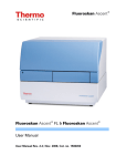
Download Fluoroskan Ascent FL User Manual
Transcript
Cat. no. 150 6450 Type 374 User Manual Revision 1.4 1.3.1999 Copyright (c) 1995-1999 SYMBOLS AND MARKINGS SYMBOLS USED IN THE FLUOROSKAN ASCENT AND THE FLUOROSKAN ASCENT FL Power ON Power OFF Connection to the protective earthing system WARNING MARKINGS USED ON THE INSTRUMENT Caution: risk of electric shock. Caution: risk of personal injury to the operator or a safety hazard to the surrounding area. See the accompanying documentation. WARNING MARKINGS USED IN THE DOCUMENTATION Caution: risk of electric shock. Caution: risk of personal injury to the operator or a safety hazard to the surrounding area. Caution: risk of serious damage to the instrument, other equipment or loss of performance or function in a specific application. 2 Fluoroskan Ascent FL & Fluoroskan Ascent User Manual CONTENTS SYMBOLS AND MARKINGS........................................................................2 1. INTRODUCTION.......................................................................................... 5 2. INSTRUMENT LAYOUT ............................................................................. 7 2.1 2.2 2.3 VIEW 2.4 2.5 2.6 2.7 2.8 3. METHOD DESCRIPTIONS....................................................................... 12 3.1 3.2 3.3 4. UNPACKING......................................................................................... 14 ENVIRONMENTAL REQUIREMENTS AND NOISE........................... 14 RELEASING THE TRANSPORTATION LOCK .................................. 15 POWER AND COMPUTER CONNECTIONS ....................................... 16 DISPENSERS......................................................................................... 17 SPECIFICATIONS ...................................................................................... 19 5.1 5.2 5.3 5.4 6. FLUOROMETRIC MEASUREMENT PRINCIPLE................................ 12 OPTICAL SYSTEM............................................................................... 12 LUMINOMETRIC MEASUREMENT PRINCIPLE................................ 13 INSTALLATION ......................................................................................... 14 4.1 4.2 4.3 4.4 4.5 5. FLUOROSKAN ASCENT/FLUOROSKAN ASCENT FL FRONT VIEW 7 FLUOROSKAN ASCENT/FLUOROSKAN ASCENT FL REAR VIEW... 8 FLUOROSKAN ASCENT/FLUOROSKAN ASCENT FL INTERNAL 9 CONTROL SWITCHES ........................................................................... 9 INCUBATOR......................................................................................... 10 EXCITATION BEAM SELECTOR........................................................ 10 DISPENSERS......................................................................................... 10 PLATE CARRIAGE............................................................................... 11 GENERAL SPECIFICATIONS .............................................................. 19 SAFETY SPECIFICATIONS ................................................................. 20 IN CONFORMITY WITH THE EU DIRECTIVES................................. 21 PERFORMANCE SPECIFICATIONS.................................................... 22 OPERATION............................................................................................ 24 6.1 SWITCHING ON ................................................................................... 24 6.2 FLUOROMETRIC MEASUREMENT.................................................... 24 6.2.2 Scaling............................................................................................ 26 6.2.3 Dynamic Series Test Solutions ........................................................ 27 6.3 LUMINOMETRIC MEASUREMENT.................................................... 29 Fluoroskan Ascent FL & Fluoroskan Ascent User Manual 3 6.3.1 Luminometric Scaling..................................................................... 30 6.4 OTHER FUNCTIONS............................................................................ 30 6.4.1 Orbital Shaking .............................................................................. 30 6.4.2 Incubator ........................................................................................ 33 6.4.3 Dispensers ...................................................................................... 33 6.4.4 Dispenser Tip Height Adjustment ................................................... 35 6.4.5 Chemical Resistance of the Dispenser ............................................ 36 6.4.6 Excitation Light Beam Selector....................................................... 39 6.4.7 Area Measurements ........................................................................ 40 6.5 CHANGING THE MEASUREMENT DIRECTION............................... 40 6.6 INSTALLING OR REMOVING THE LIGHT SHIELD.......................... 43 6.7 INSTALLING THE FILTERS ................................................................ 44 7. MAINTENANCE ......................................................................................... 46 7.1 ROUTINE CLEANING OF THE INSTRUMENT .................................. 46 7.2 CLEANING THE OPTICAL SYSTEM.................................................. 47 7.3 CLEANING THE MEASUREMENT CHAMBER.................................. 47 7.4 CLEANING THE PLATE CARRIAGE.................................................. 49 7.5 DISINFECTION PROCEDURE ............................................................. 50 7.6 REPLACING THE FUSES..................................................................... 51 7.7 REPLACING THE HALOGEN LAMP .................................................. 51 7.8 ROUTINE MAINTENANCE OF OPTIONAL DISPENSERS ............... 52 7.8.1 Daily Maintenance.......................................................................... 52 7.8.2 Weekly Maintenance....................................................................... 53 7.9 PERIODIC MAINTENANCE ................................................................ 54 7.9.1 Replacing the Dispenser Tubing...................................................... 54 7.9.2 Replacing the Dispensing Tip ......................................................... 56 7.9.3 Replacing the Dispenser Syringe..................................................... 56 7.9.4 Replacing the Dispenser Syringe Seal ............................................. 57 7.9.5 Replacing the Dispenser Valve........................................................ 58 7.10 WARRANTY STATEMENT ................................................................. 59 7.10.1 Conditions and Exclusions.............................................................. 59 8. DECONTAMINATION............................................................................... 60 8.1 8.2 9. ORDERING INFORMATION .................................................................... 62 9.1 9.2 9.3 4 CERTIFICATE OF DECONTAMINATION .......................................... 60 SHIPPING THE INSTRUMENT (OR ITEMS) ........................................ 61 ORDERING FILTERS ........................................................................... 65 WHY THE ORDERING INFORMATION IS SO IMPORTANT ............ 67 FILTER PAIR AND APPLICATION ..................................................... 69 Fluoroskan Ascent FL & Fluoroskan Ascent User Manual APPENDIX 1.................................................................................................... 70 1. INTRODUCTION The Fluoroskan Ascent from Labsystems is a microplate fluorometer which offers versatility and flexibility for even the most demanding fluorometric applications. The extended Fluoroskan Ascent FL is equipped with both fluorometric and luminometric detection technologies. As a combination instrument it covers the full range of fluorometric as well as glow and flash luminometric applications. Figure 1. The Fluoroskan Ascent by Labsystems Ascent Software controls all the reader functions and provides easy assay optimization, flexible data handling and convenient report formatting. The software for the Fluoroskan Ascent is a dedicated software for fluorometric applications, while the software for the Fluoroskan Ascent FL enables both fluorometric and luminometric detection methods to be used, even during a single session. The advanced optical system based on direct illumination optics, with a highly focused light beam for fluorometric measurements, prevents crosstalk and ensures accurate readings. The choice of two beam diameter settings allows optimal reading of 1 to 96 and 384 wells. High sensitivity is one of the main benefits of fiberless optics and a critical feature for luminometry. The Fluoroskan Ascent FL & Fluoroskan Ascent User Manual 5 Fluoroskan Ascent FL can also be equipped with filters for luminometric applications. Up to three reagent dispensers can be fitted on-board, making the reagent addition simple and highly accurate. The ability of the instrument to dispense and measure simultaneously enables the detection of flash luminescence 2+ reactions, fluorometric Ca measurements and other rapid kinetic applications. For assays requiring temperature control, these instruments have an on-board incubator. Built-in orbital shaking speeds up reaction times and ensures effective mixing. Robotic integration is simple and effective with the Fluoroskan Ascent and the Fluoroskan Ascent FL. The plate carrier allows convenient access for the robotic arm and Ascent Software is easy to integrate with robotic and HIS/LIMS systems. The Fluoroskan Ascent and Fluoroskan Ascent FL are also fully compatible with the Labsystems Assist Plate Handling Device, expanding the measurement capacity up to over 100 pieces of 384-well plates without manual operation. For further information about the Assist, contact your local Labsystems representative. 6 Fluoroskan Ascent FL & Fluoroskan Ascent User Manual 2. INSTRUMENT LAYOUT 2.1 VIEW FLUOROSKAN ASCENT/FLUOROSKAN ASCENT FL FRONT 1 2 5 4 3 Figure 2.1 Front view 1. Instrument housing 2. Dispenser and optics cover 3. Instrument chassis 4. Measurement chamber door 5. Power, busy and error indicator Fluoroskan Ascent FL & Fluoroskan Ascent User Manual 7 2.2 FLUOROSKAN ASCENT/FLUOROSKAN ASCENT FL REAR VIEW 6 7 5 3 4 1 2 Figure 2.2 Rear view 1. Mains power socket 2. Power ON/OFF switch 3. Power fuses 4. Serial communication connector for the computer 5. Identification plate 6. Housing retaining screws 7. Cooling-air outlet 8 Fluoroskan Ascent FL & Fluoroskan Ascent User Manual 2.3 VIEW FLUOROSKAN ASCENT/FLUOROSKAN ASCENT FL INTERNAL 1 2 7 3 5 4 6 Figure 2.3 Internal view 1. Light cover for the optical unit 2. Optional dispensers 3. Optional dispensing tips 4. Optional leakage tray 5. Optional dispensing tip holder 6. Dummy tip 7. Control switches in the Fluoroskan Ascent FL 2.4 CONTROL SWITCHES The control switch box (FL only) contains three rocker switches for priming and emptying dispenser tubings, one rocker switch for driving the plate carrier in or out, and a limit switch to secure the dispenser cover closed position in luminometric measurements. Fluoroskan Ascent FL & Fluoroskan Ascent User Manual 9 2.5 INCUBATOR The incubator contains two heating element plates in the measurement chamber, one heating element plate under the microplate and another above it. The incubator only heats, but does not cool. 2.6 EXCITATION BEAM SELECTOR The excitation beam selector makes it possible to select the optimal beam to measure different sizes of wells. The normal beam, diameter 3 mm, is recommended for 96-well plates and larger wells. The small beam, diameter 1.5 mm, is recommended e.g. for 384-well plates. The beam selector is situated in the optics module. A manually operated knob changes the diameter of the light beam and the instrument automatically detects the position of the knob. 2.7 DISPENSERS The dispensers, 1 to 3 pieces from left to right, are located inside the instrument housing under the dispenser cover, as seen in Figure 2.3 Internal view. The dispensers consist of modular digital pumps with valves, syringes, tubing and dispensing tips. The dispensing tips have three alternative dispensing positions, one of these dispenses into the well in the measurement position. 10 Fluoroskan Ascent FL & Fluoroskan Ascent User Manual 2.8 PLATE CARRIAGE 4 3 2 1 Figure 2.5 The plate carriage 1. Positioning lever 2. Removable stoppers 3. Fluorescence reference chips 4. Optional waste strip holder (4 wells) for the prime tip function Fluoroskan Ascent FL & Fluoroskan Ascent User Manual 11 3. 3.1 METHOD DESCRIPTIONS FLUOROMETRIC MEASUREMENT PRINCIPLE Measurement with the Fluoroskan Ascent occurs in a narrow angle. The source of the excitation light and the detector of the emission light are both located on the same side of the microplate. Filters are held in 8-position filter wheels. Excitation and emission wavelengths of common fluorochromes fall into the measurement range of the Fluoroskan Ascent. The Fluoroskan Ascent can read from above or below the plate. The position of the whole optic unit is easily changed. 3.2 OPTICAL SYSTEM 1 7 6 2 3 5 4 Figure 3.2 The principle of the optical system 1. The light source is a quartz-halogen lamp. 2. Excitation filter in the excitation filter wheel. 3. Lamp reference detector. 4. The highly focused excitation light beam in the well to be measured. The diameter of the normal beam in the sample is about 3 mm and that of the optional small beam about 1.5 mm. 5. In the Fluoroskan Ascent FL, the emission light beam is also strictly limited with a light shield to avoid crosstalk in luminometric measurements. 12 Fluoroskan Ascent FL & Fluoroskan Ascent User Manual 6. Emission filter in the emission filter wheel. 7. The photomultiplier tube detects the emission light. 1 3.3 LUMINOMETRIC MEASUREMENT PRINCIPLE A luminometric measurement uses the same optics as the fluorometric but the lamp is switched off. The emission filter slots 7 and 8 are reserved only for luminometric measurements. Filter slot 7 is empty for measurement and filter slot 8 is blocked to enable measurement of the PMT (photomultiplier tube) dark current. This feature is important to obtain the optimal sensitivity. The light path from the measurement well to the first lens is protected by a light shield. The light shield is necessary to avoid crosstalk in luminometric measurements. The standard light shield is for 96-well plates. 384-well plates can also be measured if the plate height is about 15 mm. An adapter must be used with lower plates in order to raise the plate. The light shield is necessary in luminometric measurements and does not interfere with fluorometric measurements. When plates are higher than 15 mm, the standard light shield must be removed. Caution: A luminometric measurement without a light shield may cause extra crosstalk. Caution: The light shield must be removed with higher plates. 1 Only in the Fluoroskan Ascent FL. Fluoroskan Ascent FL & Fluoroskan Ascent User Manual 13 4. INSTALLATION 4.1 UNPACKING The Fluoroskan Ascent/ Fluoroskan Ascent FL is packed in a single box. Place the box on the floor and open it carefully. Examine the contents for any damage that may have occurred during transportation. Compare the contents to the included packing list. If any parts are damaged or missing, contact your local Labsystems representative. Retain the original packaging for future transportations. Intended lifting area Figure 4.1 The Fluoroskan Ascent 4.2 ENVIRONMENTAL REQUIREMENTS AND NOISE Locate the Fluoroskan Ascent/Fluoroskan Ascent FL in such a place to avoid exposure to dust, vibrations, strong magnetic fields, direct sunlight, drafts, large temperature variations and excessive moisture. A normal laboratory bench close to the mains supply socket is suitable. Leave sufficient clearance at both sides of the instrument and at the back of the unit to allow adequate air circulation. Also reserve a space for the controlling computer on one side of the Fluoroskan Ascent/Fluoroskan Ascent FL. 14 Fluoroskan Ascent FL & Fluoroskan Ascent User Manual The Fluoroskan Ascent/Fluoroskan Ascent FL does not produce operating noise at a level which could cause a hazard. No sound level measurements are needed after installation. 4.3 RELEASING THE TRANSPORTATION LOCK 2 3 4 Figure 4.3a Removing the instrument cover 1 1. Remove the cover retaining screws, 4 pcs. 2. Open the dispenser and optics cover. 3. Lift the rear of the cover at first about 3 cm. 4. Lift the cover aside. 5. Undo the two screws at the right rear corner of the measurement chamber. 6. Turn the locking piece upside down. 7. Fit the locking piece back with the fitting screws. 8. Refit the cover by first fixing the front corners. 5 6 7 Fluoroskan Ascent FL & Fluoroskan Ascent User Manual 15 Figure 4.3b Removing the transportation lock Caution: If the locking piece is not fitted into its place, light may enter the measurement chamber and affect the results. 4.4 POWER AND COMPUTER CONNECTIONS 4 2 1 Figure 4.4 Power and computer connections 1. Ensure the mains switch is in the OFF position. 2. Connect the mains supply cord to the mains power socket. The instrument box contains two different mains supply cords with North American and European types of plugs. Select the correct type used in your laboratory. If any other type of mains supply cord is needed, use only cords certified by the local authorities. The power supply has an automatic 100-120/200-240 VAC range selection. 3. Connect the instrument to a correctly installed line power outlet that has a protective conductor also called earth or ground. 16 Fluoroskan Ascent FL & Fluoroskan Ascent User Manual Caution: Interruption of the protective conductor inside or outside the instrument or disconnection of the protective conductor terminal may make the instrument dangerous. 4. Connect the serial cable to the serial connector and secure it with the locking screws. Connect the other end similarly to the controlling computer. If the serial connector of the computer is of a 25 pin type, you will need a new cable (see chapter 9). 4.5 DISPENSERS The dispensers 1 to 3 are installed in number order from left to right. The 1 tubing and the dispensing tip are packed with the accessories. Fit the aspirate tubing into the left hole of the valve and tighten it finger-tight. Using a 7.9 mm (5/16”) wrench, turn the fitting another quarter to half turn. The aspirate tubing is used to fill the syringe with reagent. Fit the dispensing tube assembly into the right hole of the valve and tighten it finger-tight. Using a 7.9 mm (5/16”) wrench, turn the fitting another quarter to half turn. The dispensing tube is used to dispense reagent from the syringe into a microplate. Place the dispensing tip in the tip holder on the left side of the dispensers. 1 Instructions concerning the pump are reproduced from CAVRO XP3000 Modular Digital Pump Operators Manual made by Cavro Scientific Instruments, Inc., USA, 1994. Fluoroskan Ascent FL & Fluoroskan Ascent User Manual 17 1 2 3 4 5 Figure 4.5 Dispenser tubing 1. Aspirate tubing 2. Dispensing tube assembly 3. Valve 4. Syringe and plunger 5. Plunger lock screw 18 Fluoroskan Ascent FL & Fluoroskan Ascent User Manual 5. SPECIFICATIONS Labsystems reserves the right to change any specifications without prior notice as part of our continuous product development program. 5.1 GENERAL SPECIFICATIONS Weight Basic unit 21 kg. 3 optional dispensers add 3.5 kg to the weight. Overall dimensions 420 mm (W) x 420 mm (D) x 340 mm (H), options included. Operating conditions (indoor use) +10°C - +40°C, RH 90% max. Tested according to IEC 68-2-1 test Ab, (Cold). IEC 68-2-2 test Bb, (Dry heat). IEC 68-2-3 test Ca, (Damp heat). Transportation conditions -40°C - +70°C, packed in transportation packaging. Tested according to IEC 68-2-1 test Ab, (Cold). IEC 68-2-2 test Bb, (Dry heat). Storage conditions -25°C - +50°C, packed in transportation packaging. Tested according to IEC 68-2-1 test Ab, (Cold). IEC 68-2-2 test Bb, (Dry heat). Mains power supply 100-120 VAC, 50/60 Hz, nominal (operating range 90-136 V), or 200-240 VAC, 50/60 Hz, nominal (operating range 180-256 V) (see mains supply fluctuations below). An automatic range selection. Fuses 2 x 3.5 A/250 V, UL 198G Time Delay, 5 x 20 mm. Power consumption 200 VA max., 32 VA standby. Computer interface Serial RS-232C port. Baud rate 9600. Character format 1 start bit, 8 data bits, 1 stop bit, no parity. Flow control XON/XOFF. Light source Quartz-halogen lamp. Power consumption 30W. Detector Photomultiplier tube. Fluoroskan Ascent FL & Fluoroskan Ascent User Manual 19 Fluorescence reference Lisa KL 3-9402 Polymethylmethacrylate. Filters for fluorometric measurements High-quality wideband interference filters. Both excitation and emission filter wheels comprise max. eight selectable filters. Transmittance 30 65%, half-bandwidth 14 - 50 nm, depending on the wavelength. In the Fluoroskan Ascent FL the emission filter slots 7 and 8 are reserved for luminometric measurements. Filters for luminometric measurements Filters can be used. Luminometric filters and fluorometric emission filters are situated in the same filter wheel, altogether 6 pcs. Plate types 1-, 6-, 12-, 24-, 48-, 96-, and 384-well plates. Can also be programmed for non-standard configurations. Maximum dimensions 90 mm x 134 mm x 25 mm. Shaker Built-in orbital shaker with adjustable speed and diameter. Incubator Temperature range from ambient temperature +3°C to +45°C. The temperature is selected using Ascent Software. Dispensers 1 - 3 optional dispensers. Syringe volumes 1000 µl. Dead volume 600 µl. Metal-free fluid path. Exchangeable valve, syringe, tubing and tip. Autoclavable tubing and tip. 5.2 SAFETY SPECIFICATIONS The Fluoroskan Ascent/ IEC 1010-1 including Amendments 1 and 2. CSA C22.2 No 1010.1 (file LR 62464-C). Fluoroskan Ascent FL fulfils the following requirements: The safety specifications are also met under the following environmental conditions in addition or in excess to those stated in the operating conditions: 20 Fluoroskan Ascent FL & Fluoroskan Ascent User Manual Altitude up to 2000 m. Temperature +5°C - +40°C. Mains supply fluctuations ± 10% (if larger than specified above). Installation category (overvoltage category) II according to IEC 664-1 (note 1). Pollution degree 2 according to IEC 664-1 (note 2). Notes 1) The installation category (overvoltage category) defines the level of transient overvoltage which the instrument is designed to withstand safely. It depends on the nature of the electricity supply and its overvoltage protection means. For example, in CAT II which is the category used for instruments in installations supplied from a supply comparable to public mains, such as hospital and research laboratories and most industrial laboratories, the expected transient overvoltage is 2500 V for a 230 V supply and 1500 V for a 120 V supply. 2) The pollution degree describes the amount of conductive pollution present in the operating environment. Pollution degree 2 assumes that normally only nonconductive pollution, such as dust, occurs with the exception of occasional conductivity caused by condensation. Both of these affect the dimensioning of the electrical insulation within the instrument. 5.3 IN CONFORMITY WITH THE EU DIRECTIVES The Fluoroskan Ascent/ 89/336/EEC (as amended by 92/31/EEC) relating to Electromagnetic Compatibility. Fluoroskan Ascent FL 73/23/EEC (Low Voltage Directive). bearing the CE mark conforms to the following EU Directives: The performance specifications used to verify conformance to the Directives above: EN 55022 class B IEC 1000-4-3/ EN 61000-4-3 3 V/m IEC 1000-4-2/ EN 61000-4-2 4 kV CD, 8 kV AD IEC 1000-4-4/ EN 61000-4-4 kV IEC 1010-1/ EN 61010-1 including Amendments 1 and 2. Fluoroskan Ascent FL & Fluoroskan Ascent User Manual 21 5.4 PERFORMANCE SPECIFICATIONS Warming-up time < 15 min. to rated accuracy. Measuring speed Depends on the plate type and the measurement type. The minimum kinetic interval time is 15 s for a 96-well plate (from well A1 back to the same well A1). Excitation wavelengths 320 - 700 nm Fluorometric measurement range Up to 5000 Relative Fluorescence Units (RFU) Emission wavelengths Fluoroskan Ascent FL 360 - 670 nm, optional 360 - 800 nm Fluoroskan Ascent 360 - 800 nm Fluorometric sensitivity 0.01 pmol Fluorescein in a black 96-well plate, normal beam. Limit = (2 x SDBlank) / IRef-Blank x CRef Fluorometric dynamic range > 5 decades Fluorescein in a black 96-well plate Luminometric spectral range 270 - 670 nm Luminometric measurement range Up to 5000 Relative Light Units (RLU) Luminometric sensitivity in FL only 5 fmol ATP in a white 96-well plate (Labsystems ATP monitoring kit). Limit = (2 x SDBlank) / IRef-Blank x CRef Luminometric dynamic range in FL only Instrument dynamic range 7 decades Shaker Orbital method, speed 60 -1200 rpm, ∅ 1 - 50 mm 22 Fluoroskan Ascent FL & Fluoroskan Ascent User Manual Incubator Warming-up time of the heaters 15 min. Temperature accuracy: Mean temperature of the wells ± 1°C, Uniformity: ≤ 1°C (ambient temperature +23°C, covered 96-well plate). Warming-up speed 1 h from 23°C to 37°C on an average 90% of the set value (ambient temperature +23°C, covered 96-well plate, 200 µl/well). Dispensers Dispensing volume 5 - 1000 µl in 5 µl increments. Accuracy ± 3 µl avg. Precision 5 - 15 µl < 5% 20 - 1000 µl < 2% Minimum dispensing speed 25 s, 96-well plate, 5 µl/well. Fluoroskan Ascent FL & Fluoroskan Ascent User Manual 23 6. OPERATION The Fluoroskan Ascent/Fluoroskan Ascent FL is fully computer-controlled. Labsystems Ascent Software controls the reader functions and provides complete data handling and report formatting. For further details on how to use the software, see the Ascent Software User’s Guide. The instrument is equipped with a power ON/OFF switch and a three-color LED indicator. When the instrument is switched ON, the color indicates the state of the instrument: Green The instrument is ready and waiting for a command. Orange The instrument is busy, executing a command. Red The instrument has found an error, the error message is sent to the computer and the computer has not acknowledged it. 6.1 SWITCHING ON When switched on, the instrument performs the following initialization tests and adjustments: 1. The measurement system is tested using an internal test signal, then different gain steps are tested and adjusted. 2. Both filter selection systems are tested and the filters in position 1 are selected. 3. X and Y movements of the plate carriage are tested and the carriage is driven out. 4. When all the initialization tests and adjustments are performed successfully, the indicator LED turns green and the instrument is ready to receive computer commands. The recommended warming-up time is 15 minutes, but the instrument will perform commands immediately after the initialization period. 6.2 FLUOROMETRIC MEASUREMENT A measurement function has several phases: 1. The instrument switches on the halogen lamp and waits for 5 seconds to balance the intensity if it was off. The lamp is switched off if the instrument is idle and has not received any commands from the computer in 3 minutes. 24 Fluoroskan Ascent FL & Fluoroskan Ascent User Manual 2. The anode voltage of the PMT is selected according to the selected excitation wavelength to compensate for the spectra of the halogen lamp. 3. Selected filters are driven to the measurement positions by rotating the excitation and emission filter wheels. 4. The plate carriage is driven in, if it was out, and the reference chip corresponding to the selected filter pair is driven to the measurement position. 5. In the autocalibration procedure the instrument reads the fluorescence from the reference chip, compares it to the value in memory and sets a factor to correct the reading. The original chip value is in memory and due to the drift of the PMT and the decay of the lamp, the measured chip value may differ slightly from the original one. This difference is used to correct the reading in order to get the original signal levels. Also see chapter 6.2.1 Validation. In long measurement procedures the autocalibration is performed in a suitable phase without disturbing the measurement timing. The time interval between autocalibrations is 5 minutes. 6. After autocalibration the wells are measured according to the selected measurement parameters. The A/D converter has several gain steps, but the instrument selects automatically the best gain in each measurement. 7. The plate carrier acceleration and maximum speed are adjustable, see the Ascent Software User’s Guide: General step/Settings. Caution: When measuring large wells with liquid type samples, high speed and acceleration may cause splashing and extra variation in the results. Use the default acceleration 2 for 48-well plates and the default acceleration 1 for microplates with 24 or less wells. Fluoroskan Ascent FL & Fluoroskan Ascent User Manual 25 6.2.1 Validation 1. In the validation procedure a new filter pair is introduced to the autocalibration system. The Fluoroskan Ascent has a special automatic gain selection to obtain the optimal dynamic range without any adjustments. The automatic gain selection optimizes the relation between the excitation and emission wavelengths and the anode voltage of the photomultiplier tube to compensate for the halogen lamp intensity spectra as well as PMT spectral response. The validation procedure always uses only the normal beam. You can find the filter pair validation procedure in Ascent Software. The menu selection is Setup/Filters. 2. The instrument reads the fluorescence values of all the reference chips, selects the chip for which the value is suitable, neither too low, nor too high. The selected value is saved in memory for the autocalibration procedure. 3. If the validation procedure does not find a suitable reference chip, the program asks if the user still wants to use this filter pair. If the answer is ‘yes’, the pair can be used in measurements, the only difference is that the autocalibration procedure cannot form a correction factor to compensate for the drifts mentioned in the previous chapter. Other compensations, such as the excitation intensity compensation with the reference channel, remain in the autocalibration procedure. 4. Ascent Software shows the validated filter pairs and those pairs which have not found a suitable chip are marked with an asterisk. 6.2.2 Scaling 1. The measured results are obtained in Relative Fluorescence Units (RFU), as no standard fluorescence units exist. Scaling is a way to convert readings to show desired values. The normal beam and the small beam have separate scaling factors. 2. Prepare a scaling reference solution and a blank solution and pipette several wells of blanks and the known concentration. 3. Measure the wells using the correct filter pair and beam. 4. Calculate the average values of the measured reference values and blank values. The blank values should be very small compared to the reference values. 5. Calculate the scaling factor using calculated average values: Factor = Known reference / (Measured reference - Measured blank) 26 Fluoroskan Ascent FL & Fluoroskan Ascent User Manual Example • The known concentration is 500 pmol/well. • The calculated average of the measured reference wells is 1825 RFU. • The calculated average of the measured blank wells is 0.2 RFU. • Factor = 500 / (1825 - 0.2) = 0.274 • After scaling the measured result is: 0.274 x 1825 RFU = 500 pmol/well. 1. You can find the filter pair scaling entry in Ascent Software. The menu selection is Setup/Filters. Select the corresponding filter pair and key in the scaling factor. The following filter pairs, if any of these exist in the instrument, are scaled in the factory with the normal beam as follows: Filter pair Scaling Reference Scaled Reading Ex 355 nm, Em 460 nm 1000 pmol 4-MeU, Sigma M-1381 1000 Ex 485 nm, Em 538 nm 250 pmol FITC, Sigma F-7250 250 Ex 544 nm, Em 590 nm 625 pmol TRITC, Sigma T-5646 625 Ex 584 nm, Em 612 nm 500 pmol Texas Red, Sigma S5385 500 6.2.3 Dynamic Series Test Solutions Dynamic series for the Fluoroskan Ascent filter pair ex 485 nm/em 538 nm. Fluorescein (Sigma F-6377, M = 376.3 g/mol, store at amb. temp.). Fluoroskan Ascent FL & Fluoroskan Ascent User Manual 27 Reagents 0.01 M PBS, pH 9.0 (dilution buffer): K2HPO4·3 H2O (M = 228.23 g/mol) 2.28 g NaCl 9.0 g (M = 58.44 g/mol) Deionized water ad. 1000 ml Adjust the pH if necessary with a few drops of 0.1 N NaOH to pH 9.0. 25 mmol/l Fluorescein (stock solution) Fluorescein (Sigma F-6377, M = 376.3 g/mol) 94 mg ethanol 94% 3 ml 0.1 M PBS, pH 9.0 ad. 10 ml Dilution series No. pmol/100 µl 13 5000 100 µl Fluorescein (stock sol.) ad. 50 ml PBS, pH 9.0 12 1000 2 ml dilution 13 ad. 10 ml “ (+ 8 ml) 11 100 1 ml dilution 12 ad. 10 ml " (+ 9 ml) 10 50 3 ml dilution 11 ad. 6 ml " (+ 3 ml) 9 10 1 ml dilution 11 ad. 10 ml " (+ 9 ml) 8 5 3 ml dilution 9 ad. 6 ml " (+ 3 ml) 7 1 1 ml dilution 9 ad. 10 ml " (+ 9 ml) 6 0.5 3 ml dilution 7 ad. 6 ml " (+ 3 ml) 5 0.1 1 ml dilution 7 ad. 10 ml " (+ 9 ml) 4 0.05 3 ml dilution 5 ad. 6 ml " (+ 3 ml) 3 0.025 2 ml dilution 5 ad. 8 ml " (+6 ml) 2 0.01 1 ml dilution 5 ad. 10 ml " (+ 9 ml) 1 0.005 3 ml dilution 2 ad. 6 ml " (+ 3 ml) BLANK 28 Make the dilutions in 10 ml tubes as follows: 0.01 M PBS, pH 9.0 Fluoroskan Ascent FL & Fluoroskan Ascent User Manual Pipetting Use a Black Combiplate 8 (Labsystems) Blank: 100 µl/well in eight replicates into column 1 Dilutions: 100 µl/well dilutions 1 - 9 in eight replicates into columns 2 - 10 100 µl/well dilutions 10 - 13 in four replicates into columns 11 - 12. 6.3 LUMINOMETRIC MEASUREMENT Only the Fluoroskan Ascent FL can measure luminometric labels. Luminometric reading is optimized for 96- and 384-well plates and reading is carried out from above. To obtain the best sensitivity and the lowest crosstalk, a light shield between the optics and the plate must be used. The light shield does not interfere in fluorometric measurements. In luminometric measurements the dispenser cover must be closed. Reading 1- to 48-well plates as well as reading from below the plate may cause problems in luminometric measurements, because the light shield cannot be used and most of these plates are transparent, which enables light leakage from one well to another. A measurement function has several phases: 1. The anode voltage of the PMT is set according to the selected value of the software. 2. The excitation filter wheel is driven in between the two filter positions and the excitation light is blocked even when the light is off. The emission filter slot 8 (= block) is held in place until the plate door is closed. The selected filter is then driven to the measurement positions. The emission filter slot 8 is also used for the blanking procedure to compensate for the PMT drift. 3. In the blanking procedure the instrument reads the PMT dark signal if the dark signal is drifting. If the bottom value is drifting, the results are compensated. To obtain the most accurate results, the measurement time of the dark must be as long as the measurement time of the sample. The measurement time of the dark is divided into two parts. The first half is measured before the sample measurement and the second half after the sample measurement. The selection in the settings of a session, ‘Execute by 1...n wells’, also controls blanking so that the whole selected group of wells is measured using common blanking. Fluoroskan Ascent FL & Fluoroskan Ascent User Manual 29 6.3.1 Luminometric Scaling The measured results are obtained in Relative Light Units (RLU) as no standard luminescence units exist. Scaling is performed similarly as in fluorometric scaling. 6.4 OTHER FUNCTIONS 6.4.1 Orbital Shaking The track movement system can perform the shaking action. The speed is adjustable from 60 to 1200 rpm (revolutions per minute) and the diameter of the orbital movement is adjustable from 1 to 50 mm. Some combinations of speed and diameter would cause too high g-forces inside the well area resulting in spills inside the measurement chamber. Therefore, only certain combinations are available. When you use plates with small wells, such as plates with 48 wells or more, you can select any of these available speed and diameter combinations to serve your application best. The following tables show the recommended and the not recommended but available and unavailable speed and diameter combinations with different plate types. These tables are based on the liquid used being of a low viscosity like water and the volumes being appropriate (the wells are not full). The grey area in the tables show the recommended, the black area the not recommended, and the white area the prevented speed and diameter combinations. 30 Fluoroskan Ascent FL & Fluoroskan Ascent User Manual S/D 60 120 180 240 300 360 420 480 540 600 660 720 780 840 900 960 1020 1080 1140 1200 1 2 3 4 5 6 7 8 9 10 11 12 13 14 15 16 17 18 19 20 21 22 23 24 25 Table 6.3a Available shaking parameters with 48-, or more, well plates. S/D 60 120 180 240 300 360 420 480 540 600 660 720 780 840 900 960 1020 1080 1140 1200 1 2 3 4 5 6 7 8 9 10 11 12 13 14 15 16 17 18 19 20 21 22 23 24 25 Table 6.3b Available shaking parameters with 24-well plates. Fluoroskan Ascent FL & Fluoroskan Ascent User Manual 31 S/D 1 2 3 4 5 6 7 8 9 10 11 12 13 14 15 16 17 18 19 20 21 22 23 24 25 60 120 180 240 300 360 420 480 540 600 660 720 780 840 900 960 1020 1080 1140 1200 Table 6.3c Available shaking parameters with 12-well plates. S/D 1 2 3 4 5 6 7 8 9 10 11 12 13 14 15 16 17 18 19 20 21 22 23 24 25 60 120 180 240 300 360 420 480 540 600 660 720 780 840 900 960 1020 1080 1140 1200 Table 6.3d Available shaking parameters with 6-well plates. 32 Fluoroskan Ascent FL & Fluoroskan Ascent User Manual 6.4.2 Incubator The incubator contains two heating element plates in the measurement chamber, one heating element plate under the microplate and another above it. Both heating element plates are temperature-controlled and the upper plate is 1.2°C warmer than the lower plate to avoid condensation on the plate lid. The measurement chamber is large to adopt different plate formats and therefore extensive evaporation may cause some variations in the temperatures between the wells. Consequently, when using incubations with long durations in the instrument, a plate lid is recommended. If the incubation period is long without any other important functions, the Fluoroskan Ascent/Fluoroskan Ascent FL automatically changes the place of the plate within the measurement chamber to obtain smaller differences in the temperatures between the wells. 6.4.3 Dispensers The dispensers, 1 to 3 pieces numbered from left to right, are located inside the instrument housing under the dispenser cover. The dispensing tips have three alternative dispensing positions, one of these dispenses into the well in the measurement position (M). The tip positions are optimized for a 96-type plate. When the dispensers are not in use, the dispensing tips may be in the tip holder, but the tip holes to the measurement chamber must be closed with dummy tips. 1 2 2 1 3 Y M X 3 Figure 6.4.3a Dispenser tip positioning 1. Dispensing into the well in the measurement position (M) 2. Dispensing into the well next to the measurement position in the Y direction 3. Dispensing into the well next to the measurement position in the X direction Fluoroskan Ascent FL & Fluoroskan Ascent User Manual 33 Before inserting the tip into a dispensing position, prime the syringe and tubing to an external priming vessel. The instrument has no internal priming vessel for priming the syringe and tubing. You can find the priming instructions in the Ascent Software User’s Guide. The minimum priming volume needed is 700 µl and the recommended volume is 2700 µl. The Fluoroskan Ascent FL also has control switches for priming the dispenser tubing. An external priming vessel is also needed. Priming is carried out as long as the corresponding switch is pressed. The instrument has a Prime Tip feature. If this function is selected in the Dispense or Dispense And Measure steps, the dispenser dispenses about 5 µl reagent into the tip priming vessels every time the valve of the dispenser has moved. This makes the volume of the first well equal to that of the others. The tip priming feature is moderate when the dispensing volumes are small, e.g. 5 - 20 µl. 1 Figure 6.4.3b The tip priming vessel (1) is a piece of a breakable strip The recommended tip priming vessel consists of four wells of a breakable 96well plate type strip. There is a holder for the tip priming vessel in the right rear corner of the plate carriage. The four-well piece of a strip should be exchanged after 400 tip primings. You may need to adjust the dispenser speed. The default setting is for a water-based liquid. You can find the adjustments and selections in Ascent Software. The stream from the tip should hit the opposite wall of the well when the dispensing starts. Therefore, when starting the dispensing, the liquid volume already in the well should be no more than half of the total well volume (e.g. the volume should be less than 200 µl in a 96-well plate). 34 Fluoroskan Ascent FL & Fluoroskan Ascent User Manual 6.4.4 Dispenser Tip Height Adjustment Plate height 13.5-15.0 Plate height 15.1-18.0 Plate height 18.1-21.0 mm, e.g. 96-well plate mm, e.g. 48-well plate mm, e.g. 24- to 6-well plates Figure 6.4.4a The dispensing tip height The correct dispenser tip height is very important to avoid contaminating neighboring wells. The correct tip height is also important to prevent the damage of the tip or the plate. The plate height is one of the template parameters and it is defined as the height of the uncovered well from the bottom of the plate, not the inside height of the well. The selected tip height, the used plate and the template selected in Ascent Software must match to avoid problems. To see the heights of plates in Ascent Software, select Setup and edit Plate Templates. Some 384-well plates are lower than the standard 96-well plates. If the plate height is lower than 13.5 mm, an adapter must be used to raise the plate. Measure the height of the plate and the adapter together and enter this value to the plate template. If a small well is far away from the dispensing tip, the liquid may not enter the correct well. Caution: Plate manufacturers may change the dimensions of plates without any notice or change in order numbers. Check the dimensions when you start using plates from a new box. Fluoroskan Ascent FL & Fluoroskan Ascent User Manual 35 The tip height is adjusted with red adjustment collars by moving them from either side of the fixed stopper collar: 1 2 Figure 6.4.4b Changing the position of red adjustment collars 1. Remove the dispenser tip tube from the brass tube lock. 2. The red adjustment collars can be moved from one side of the fixed collar to the other to select the correct tip height. 3. Fit the dispenser tip tube back into its place. 6.4.5 Chemical Resistance of the Dispenser 1 The following table is intended to provide guidelines for compatibility with materials used in the fluid path of the dispensers. Compatibility information is based on charts provided by the material manufacturer. Cavro recommends that each laboratory determines compatibility for their respective applications. Caution: Failure to determine compatibility of chemicals used in individual applications with the XP 3000, may result in damage to the pump and/or test results. Plastic materials used in pumps: Polysulfone: Cross Flow Manifold Assembly in the aspirate syringe Teflon® (PTFE, TFE, FEP): Tubing, valve plug, and seal Kel F®: Valve body Polypropylene: Fittings for tubing, and dispensing tip * Polypropylene - satisfactory to 22°C (72°F) ** Polypropylene - satisfactory to 49°C (120°F) 1 Instructions concerning the pump are reproduced from CAVRO XP 3000 Modular Digital Pump Operators Manual made by Cavro Scientific Instruments, Inc., USA. 36 Fluoroskan Ascent FL & Fluoroskan Ascent User Manual Classification in the table: No data available 0 No effect - excellent 1 Minor effect - good 2 Moderate effect - fair 3 Severe effect - not recommended Solvent Polysulfone Acetaldehyde Acetates Acetic Acid Acetic Anhydride Acetone Acetyl Bromide Ammonia Ammonium Acetate Ammonium Hydroxide Ammonium Phosphate Ammonium Sulphate Amyl Acetate Aniline Benzene Benzyl Alcohol Boric Acid Bromide Butyl Alcohol Butyl Acetate Carbon Sulphide Carbon Tetrachloride Chloroacetic Acid Chlorine Chlorobenzene Chloroform Chromic Acid Cresol Cyclohexane Dimethyl sulfoxide (DMSO) Ethers Ethyl Acetate Ethyl Alcohol Ethyl Chromide 0 3 0 3 2 3 0 3 3 3 0 0 3 0 - Teflon 0 0 0 0 0 0 0 0 0 0 0 0 0 0 0 0 0 0 0 0 0 0 0 0 0 0 0 0 Kel F 0 0 0 0 0 0 0 0 0 3 0 0 0 0 1 0 1 0 0 1 Fluoroskan Ascent FL & Fluoroskan Ascent User Manual Polypropylene 0 0 0 0 0 0 0 0 3 0 * 0 0 * 1 * * 3 3 3 3 * 3 0 ** 0 0 3 37 Solvent Polysulfone Formaldehyde Formic Acid Freon Gasoline Glycerine Hydrochloric Acid Hydrochloric Acid (conc.) Hydrofluoric Acid Hydrogen Peroxide Hydrogen Peroxide (conc.) Hydrogen Sulphide Kerosene Methyl Ethyl Ketone (MEK) Methyl Alcohol Methylene Chloride Naphtha Nitric Acid Nitric Acid (conc.) Nitrobenzene Phenol Pyridine Silver Nitrate Soap Solutions Stearic Acid Sulphuric Acid Sulphuric Acid (conc.) Sulphurous Acid Tannic Acid Tannin Extracts Tartaric Acid Toluene Trichlorethylene Turpentine Water Xylene 38 0 2 2 0 0 0 2 2 3 0 3 0 0 3 3 0 3 3 3 2 0 3 Teflon 0 0 0 0 0 0 0 0 0 0 0 0 0 0 0 0 0 0 0 0 0 0 0 0 0 0 0 0 0 0 0 0 0 0 Kel F 0 0 2 0 0 0 0 0 0 0 0 0 0 1 0 0 0 0 0 0 1 3 0 0 0 Polypropylen e 0 0 0 3 0 0 0 * 0 0 0 0 0 0 3 0 0 ** 0 0 0 * 0 0 0 ** 3 ** 0 * Fluoroskan Ascent FL & Fluoroskan Ascent User Manual 6.4.6 Excitation Light Beam Selector Excitation beam selection means a possibility to select the normal beam, with a diameter of 3 mm in the measurement well, or the small beam, with a diameter of 1.5 mm. The small beam is required to measure, for example, 384-well plates. If the normal beam is used with 384-well plates, the light beam also excitates the walls of the well, and the result is not optimal. Measurement of larger wells with the small beam is possible and depends on the application. Figure 6.4.6a Beam selection when measuring above the plate The selection lever of the beam is on the front panel of the optical unit. When the optical unit is above the plate, the selection knob can be seen through the hole in the light cover of the optical unit (see Figure 6.4.6a). When the optical unit is below the plate, the measurement chamber must be lifted up to reach the selection knob. The position of the selection knob in the optical unit is shown in Figure 6.4.6b. Figure 6.4.6b Beam selection when measuring below the plate Fluoroskan Ascent FL & Fluoroskan Ascent User Manual 39 To select the normal beam, push the button firmly, and to select the small beam, pull the button firmly. DO NOT leave the button in a middle position. The pointer on the knob also shows the position of the selection. 6.4.7 Area Measurements In area measurements, when there is more than one measurement point in a well, it is recommended to use the normal beam. The distance between two measurement positions is 1.5 mm. When you use the normal beam (Ø 3 mm), the measurement areas are overlapping and the whole area is measured. If you use the small beam (Ø 1.5 mm), the small areas between the measurement points are not measured at all. Area measurement with the normal Area measurement with the beam. The whole area is measured. small beam. The black area between the measurement points This is the recommended way. is not measured at all. Figure 6.4.7 Area measurements 6.5 CHANGING THE MEASUREMENT DIRECTION The measurement direction can be changed by moving the whole optical unit from above the measurement chamber to below the measurement chamber, or vice versa. 1. Switch off the instrument and disconnect the mains supply cord. There are anode voltages inside the power supply box and the optical unit if the power is on. 2. Remove the instrument cover, as described in section 4.3 Releasing the Transportation Lock. 3. Undo the four finger nuts to release the light cover. 4. Remove the light cover. 40 Fluoroskan Ascent FL & Fluoroskan Ascent User Manual 4 3 Figure 6.5a Removing the light cover of the optical unit 5. Undo the six screws (three screws on each side of the instrument) fixing the measurement chamber to the chassis. Lift the measurement chamber into the upper position. There are hinges in the rear and a gas spring holds the chamber in the upper position. Caution: The measurement chamber is very heavy. DO NOT leave your fingers between the measurement chamber and the bottom case. 10 9 6 5 Figure 6.5b Removing the optical unit Fluoroskan Ascent FL & Fluoroskan Ascent User Manual 41 Remove the three short finger nuts and remove the cover plate from the opposite position of the optical unit under the measurement chamber. 7 Figure 6.5c The cover plate 6. Lower the measurement chamber back into the down position. 7. Unplug the flat cable and the lamp cable from the optical unit. DO NOT remove any other parts from the optical unit. 8. Undo the three long finger nuts and remove the optical unit. 9. Lift the measurement chamber into the upper position. 10. Place the optical unit into the position where you removed the cover plate, fix it with the long finger nuts and plug in the cable connectors. No adjustments are needed. 11. Lower the measurement chamber back into the down position. 12. Place the cover plate instead of the removed optical unit and fix it with the short finger screws. 13. Fit the six screws back to hold the measurement chamber and replace the instrument cover. The unfitted cover may increase stray light and harm the measurement. 14. To change the measurement direction, the optical unit and the cover plate are interchangeable. 42 Fluoroskan Ascent FL & Fluoroskan Ascent User Manual 6.6 INSTALLING OR REMOVING THE LIGHT SHIELD The light shield is only present in the Fluoroskan Ascent FL. Light shield Positioning guide Figure 6.6a Installing the light shield 1. Switch off the instrument and disconnect the mains supply cord. 2. Remove the instrument cover, as described in section 4.3 Releasing the Transportation Lock. 3. Undo the four finger nuts and remove the light cover. 4. Undo the three long finger nuts and remove the optical unit or, if the optical unit is below the measurement chamber, remove the cover plate. 5. When removing the optical shield, use your little finger to lift the optical shield up. When installing the optical shield, be sure that the positioning guide is placed towards the front of the instrument against the corresponding guide in the holder. If the light shield is not positioned correctly, the optical unit does not slot down into its correct place but stays swinging. Fluoroskan Ascent FL & Fluoroskan Ascent User Manual 43 6. Fit the optical unit, light cover and the instrument cover back into their places. Caution: Mispositioning of the optical shield will cause disturbances in the measurement results. Positioning guide 6.6 Top view of the light shield 6.7 INSTALLING THE FILTERS 1. Switch off the instrument and disconnect the mains supply cord. 2. Remove the instrument cover, as described in section 4.3 Releasing the Transportation Lock. 3. If the optical unit is above the measurement chamber, undo the four finger nuts and remove the light cover. You can find more detailed instructions in section 6.5 Change the Measurement Direction. 4. If the optical unit is below the measurement chamber, undo the six screws fixing the measurement chamber to the chassis. Lift the measurement chamber into the upper position. There are hinges in the rear and a gas spring holds the chamber in the upper position. Caution: The measurement chamber is very heavy. DO NOT leave your fingers between the measurement chamber and the bottom case. 5. Unplug the flat cable and lamp cable from the optical unit. Undo the three long finger nuts and remove the optical unit and place it on a table. 44 Fluoroskan Ascent FL & Fluoroskan Ascent User Manual 6. The excitation filter wheel can be removed by undoing the fitting screw marked ‘6’ in Figure 6.7a. DO NOT touch the filter surfaces. 7. The emission filter wheel can be removed by undoing the fitting screw marked ‘7’ in Figure 6.7a. DO NOT touch the filter surfaces. 8. Select the filter wheel into which you want to install a filter. Normally the filters are installed in ascending wavelength order starting from position 1. Select the first free filter slot. 7 6 Emission filter wheel Excitation filter wheel Figure 6.7a The filter wheels in the optical unit 9. Undo the fitting screw. 10. Remove the filter spring. 11. Remove the spacer collar. 12. Remove the dummy filter. Install a new filter so that the small arrow on the filter rim points away from the filter wheel. The arrow shows the direction of the light flow. 13. Fit the spacer collar, filter spring and the fitting screw. Fit the filter wheel back into its place. Fluoroskan Ascent FL & Fluoroskan Ascent User Manual 45 WH 5 9 7 6 6 2 2 10 11 12 7 8 3 3 5 4 4 E E L N AME 1 8 1 Figure 6.7b Filters in a filter wheel 14. Validate the changed filter pairs, see the instructions in section 6.2.1 and the Ascent Software User’s Guide. 7. MAINTENANCE 7.1 ROUTINE CLEANING OF THE INSTRUMENT For reliable daily operation keep the instrument free of dust and spills of liquids. It is recommended that the case of the instrument is cleaned periodically. A soft cloth dampened in mild detergent is sufficient. If you believe liquid has entered the fluorometer, you should open the covers and check the interior. In case of any damage, contact your local Labsystems representative for service. If any surfaces have been contaminated with biohazardous material, a sterilizing solution must be used. The prescribed disinfection procedure, or similar routine, must be performed before returning the instrument to the supplier for service or repair. All instruments must be accompanied by a completed and signed Certificate of Decontamination securely attached to the exterior of the packaging (see section 8). 46 Fluoroskan Ascent FL & Fluoroskan Ascent User Manual 7.2 CLEANING THE OPTICAL SYSTEM Main lens Figure 7.2 Cleaning the optical unit 1. Switch off the instrument and disconnect the mains supply cord. Locate the optical unit and remove it according to the instructions in chapters 4.3 and 6.5. 2. Clean the main lens and the filters with a cloth dampened with 96% ethanol and afterwards with a lint-free cloth or a lens tissue. DO NOT use acetone to clean the optical unit. Avoid any harsh treatment. 3. Replace all the removed parts and reconnect the instrument to the mains supply. 7.3 1. CLEANING THE MEASUREMENT CHAMBER Switch off the instrument and disconnect the mains supply cord. Remove the instrument cover according to the instructions in chapter 4.3. Fluoroskan Ascent FL & Fluoroskan Ascent User Manual 47 6a 6a 4 5 3 7 6b 2 Figure 7.3 Opening the measurement chamber 2. If the optical unit is on top of the measurement chamber, remove the light cover of the optics, as described in chapter 6.5 and unplug the cables. 3. Unplug the LED cable from the extension cable. 4. Unplug the upper heater cable from the extension cable. 5. Remove the dispenser connector PC board from the dispensers by opening the connector fitting screws and release the cables from the cable ties. 6. Undo the four screws fixing the measurement chamber cover. Note the three screws with washers and the different fourth screw in the front right corner. 7. If the plate carriage is out, push it inside the door and lift the cover off. 48 Fluoroskan Ascent FL & Fluoroskan Ascent User Manual 8. Clean the measurement chamber with a cloth dampened with water. In case of spills of infectious agents, clean the chamber with disposable towels dampened with a disinfectant solution containing 2% glutaraldehyde. Also use disposable gloves. Place the disposable towels and gloves in a biohazardous waste container. 9. Rather clean the lower measurement window with distilled water. Otherwise, clean the lower measurement window first with a cloth dampened with 96% ethanol and rinse afterwards with distilled water. Wipe the window last of all with a lint-free cloth or lens tissue. 10. The plate carriage is easy to clean when the measurement chamber is open. See the instructions in the next chapter. 11. Replace all the removed parts and reconnect the instrument to the mains supply. 7.4 CLEANING THE PLATE CARRIAGE 2 1 Figure 7.4 The plate carriage 1. Clean the carriage with a cloth dampened with water. In case of any spills of infectious agents, clean the chamber with disposable towels dampened with a disinfectant solution containing 2% glutaraldehyde. Also use disposable gloves. Place the disposable towels and gloves in a biohazardous waste container. 2. Clean the reference chip protection glass with a cloth dampened with 96% ethanol and afterwards with a lint-free cloth or lens tissue. Fluoroskan Ascent FL & Fluoroskan Ascent User Manual 49 7.5 DISINFECTION PROCEDURE If there is any risk of contamination with biohazardous material, the prescribed procedure or any other corresponding disinfection procedure must be performed. We strongly recommend that the complete disinfection procedure is performed before relocating the instrument from one laboratory to another. Disinfection is not required for the proper functioning of the instrument. Disinfectant agents: • Formaldehyde solution • Ethanol • Glutaraldehyde solution 10% 70% 4% Caution: Always use disposable gloves and protective clothing and operate in a well-ventilated area. 1. Prepare the disinfectant agent: 200 ml 10% formaldehyde solution or 200 ml 4% glutaraldehyde solution (or another agent recommended by your safety officer). 2. Empty the plate carriage. 3. Switch off the power and disconnect the mains supply cord and the computer cable. 4. Disinfect the outside of the instrument using a cloth dampened with 70% ethanol. 5. Place the instrument in a large plastic bag. Ensure the lids are open. 6. Place a cloth soaked in the prepared solution into the bag. Ensure the cloth does not make contact with the instrument. 7. Close the bag firmly and leave the instrument in the bag for at least 24 hours. 8. Remove the instrument from the bag. 9. Clean the instrument using a mild detergent. 10. Remove any stains using 70% ethanol. 11. After performing this disinfection procedure, label the instrument with a signed and dated Certificate of Decontamination. 50 Fluoroskan Ascent FL & Fluoroskan Ascent User Manual 7.6 REPLACING THE FUSES 1. Switch off the Fluoroskan Ascent/Fluoroskan Ascent FL and disconnect the mains supply cord. Locate the fuse holders at the rear of the instrument. 2. Using a flat tip screwdriver, open the fuse holder to expose the fuse. 3. Replace the faulty fuse with the spare provided with the accessories or with the same certified type. 4. Reconnect the instrument to the mains supply. Should the fuse blow again, contact your local Labsystems representative for service. 1 3 2 Figure 7.6 Replacing the fuses 7.7 REPLACING THE HALOGEN LAMP 1. Switch off the Fluoroskan Ascent/Fluoroskan Ascent FL and disconnect the mains supply cord. Locate the lamp on top of the optical unit. 2. Using a flat tip screwdriver, open the two screws of the lamp connector and remove the connector. 3. Using a flat tip screwdriver, open the two screws of the lamp holder to release the lamp. 4. Replace the faulty lamp with the spare provided with the accessories. Contact your local Labsystems representative if a spare lamp is required. DO NOT touch the glass bulb with your bare fingertips. Note that the lamp is not symmetrical. The guide in the rim should point to the right. 5. Reconnect the instrument to the mains supply. Fluoroskan Ascent FL & Fluoroskan Ascent User Manual 51 1 4 3 2 Figure 7.7 Replacing the halogen lamp 7.8 ROUTINE MAINTENANCE OF OPTIONAL DISPENSERS 1 To obtain optimum performance and maximum useful life from the dispensers, it is important that the recommended cleaning maintenance instructions are followed. 7.8.1 Daily Maintenance 1. The daily maintenance procedure should be performed on a regular basis to ensure proper dispenser operation. 2. Flush the pump(s) out thoroughly with distilled or deionized water after each use. 3. The pump(s) should be primed with distilled or deionized water when not in use. 4. DO NOT allow the pump(s) to run dry for more than a few cycles. 5. Inspect the pump(s) for leaks and rectify any problems immediately. 6. Wipe up all spills on and around the dispensers immediately. 1 Instructions concerning the pump are reproduced from CAVRO XP 3000 Modular Digital Pump Operators Manual made by Cavro Scientific Instruments, Inc., USA. 52 Fluoroskan Ascent FL & Fluoroskan Ascent User Manual 7.8.2 Weekly Maintenance Clean the fluid path thoroughly using one of the procedures outlined below. There are three ways that the dispensers may be cleaned: • Weak detergent • 10% bleach • Weak acid and base 7.8.2.1 Weak Detergent or 10% Bleach Remove the dispensing tips from the dispensing positions and DO NOT let any cleaning fluids enter the measurement chamber. Use external containers. 1. Prime the pump with a weak detergent or 10% bleach solution and leave it in the pumps with the syringe plungers fully lowered for 30 minutes. 2. After the 30 minute period, remove the aspirate tubing from the detergent or bleach solution and cycle all the fluid from the syringes and tubing into a waste container. 3. Prime the instrument a minimum of 10 cycles with distilled or deionized water. Leave the fluid pathways filled for storage. 7.8.2.2 Weak Acid and Base in Sequence Remove the dispensing tips from the dispensing positions and DO NOT let any cleaning fluids enter the measurement chamber. Use external containers. 1. Prime the pumps with 0.1 N NaOH and leave the solution in the pumps for 10 minutes with the syringe plungers fully lowered. 2. Flush the pumps with distilled or deionized water. 3. Prime the pumps with 0.1 N HCl and leave the solution in the pumps for 10 minutes with the syringe plungers fully lowered. 4. After the 10 minute period, remove the aspirate tubing from the 0.1 N HCl solution and cycle all the fluid from the syringes and tubing into a waste container. 5. Prime the instrument a minimum of 10 cycles with distilled or deionized water. Leave the fluid pathways filled for storage. Fluoroskan Ascent FL & Fluoroskan Ascent User Manual 53 7.8.2.3 Measurement Chamber and Main Lens Dispensing may cause some spills or drops into the measurement chamber. It is recommended that you check the measurement chamber and the main lens of the optical unit weekly. 1. Remove the optical unit if it is above the measurement chamber, or the cover plate if the optical unit is below the measurement chamber, as described in chapter 6.4 Changing the Measurement Direction. 2. If needed, clean the main lens and the measurement chamber according to the instructions in chapters 7.2 and 7.3. 7.9 PERIODIC MAINTENANCE There are three items which require periodic maintenance: tubing, syringe seals, and valves. If they become worn out, the symptoms are: • • • • Poor precision and accuracy A variable or moving air gap Leakage Drops and spills The frequency of replacement will depend on the duty cycle, fluids used and instrument maintenance. If any of these symptoms occur and it is not obvious which component is causing the problem, the easiest and most economical way is to replace one component at a time in the following order: (1) tubing, (2) seal, and (3) valve. 7.9.1 Replacing the Dispenser Tubing 1. To remove the tubing from the valve, use a 7.9 mm (5/16”) wrench and gently loosen the fittings. Unscrew the fittings and remove the tubing. 2. To fit new tubing, insert the fitting into the valve and tighten it fingertight. Using a 7.9 mm (5/16”) wrench, turn the fitting another quarter to half turn. 3. Remove the tube weight and the connecting piece of silicone tubing from the old aspirate tubing and fit them in the new aspirate tubing. 54 Fluoroskan Ascent FL & Fluoroskan Ascent User Manual 9 6 7 5 4 Figure 7.9.1 Replacing the reagent tubing 4. To remove the dispensing tip assembly from the old reagent tubing, first remove the dispensing tip tube from the brass tube holder. 5. Remove the tip and the connecting piece of silicone tubing. 6. Remove the internal dispenser tip tube. 7. Unscrew the locking ring of the tube holder to release the reagent tubing and remove the tubing. 8. Thread the tube holder and the internal dispenser tip tube on the new reagent tubing and connect the tip with the connecting piece of silicone tubing. DO NOT tighten the locking ring of the tube holder. 9. Fit the tip and tubings into the dispenser tip tube. When you push the reagent tube gently towards the tip, the internal tip tube should be visible about 1 mm. This can be adjusted through the length of the connecting piece of silicone tubing. 10. Fit the tube holder in the dispenser tip tube and tighten the locking ring. Fluoroskan Ascent FL & Fluoroskan Ascent User Manual 55 7.9.2 Replacing the Dispensing Tip 1 2 Figure 7.9.2 Replacing the dispensing tip 1. Remove the dispenser tip tube from the brass tube holder. 2. Replace the tip connected with a small piece of silicone tubing in the reagent tube. 3. Fit the dispenser tip tube. 7.9.3 Replacing the Dispenser Syringe 1 1 4 2 3 Figure 7.9.3 Replacing the dispenser syringe 56 Fluoroskan Ascent FL & Fluoroskan Ascent User Manual 1. Remove the liquid from the syringe. 2. Loosen the plunger lock screw approximately three full turns. 3. Lower the plunger drive manually by pushing the plunger holding arm firmly. The power must be switched off. 4. Unscrew the syringe from the valve. 5. To fit the syringe, screw the syringe into the valve, pull the syringe plunger down to the plunger holder arm and screw it into place. Make sure the plunger lock screw is securely tightened. 7.9.4 Replacing the Dispenser Syringe Seal 1. Remove the syringe from the pump according to the above procedure. 2. Remove the syringe plunger from the barrel. 3. Using a single-edged razor or precision knife, carefully slice the old seal lengthwise and remove it from the plunger. Care must be taken not to damage the plunger or O rings beneath the seal. O ring Narrow lip Sharp raised edge Plunger Figure 7.9.4a Plunger and O ring configuration 4. Wet the O ring if present and plunger tip with distilled or deionized water. 5. Place the seal on a flat surface with the open end facing up. Press the plunger tip firmly into the hole until it snaps into position. 6. Place the plunger on a flat table top. Position the plunger so that the seal (from the O ring up) hangs over the edge. Slowly roll the plunger along the table edge pressing firmly on the portion of the seal below the O ring. Fluoroskan Ascent FL & Fluoroskan Ascent User Manual 57 Rotate the plunger three complete turns. This is necessary for the sharp edge of the plunger to bite into the seal to allow a secure fit. 7. Wet the seal and replace the plunger, then replace the syringe. Sharp raised edge O ring Table Figure 7.9.4b Seal installation 7.9.5 Replacing the Dispenser Valve 1. Remove the fluid from the pump. 2. Remove the syringe and tubing. 3. Remove the two Phillips head screws on the front of the valve, then remove the valve from the pump. 4. To fit the valve, first rotate the valve coupling into the position corresponding to the position of the tab of the encoder in the pump. 5. Fit the new valve by inserting the slot in the valve coupling into the tab of the encoder. The valve should be oriented so that the tube fittings are on the top and the syringe fitting is on the bottom. 6. Gently push the valve into place ensuring that the locating pins on the valve fit the holes on the pump front. 7. Replace the valve screws. Tighten a quarter to a half turn after the screws contact the valve body. 4 3 58 Figure 7.9.5 Front and rear views of the valve Fluoroskan Ascent FL & Fluoroskan Ascent User Manual 7.10 WARRANTY STATEMENT The instrument is warranted against defects in workmanship and material for a period of 12 months from the date of purchase. Any product or parts of the product found to be defective, will be repaired or replaced free of charge. 7.10.1 Conditions and Exclusions Failure must have occurred due to defective materials or workmanship. The following causes of instrument malfunctions specifically excluded from the Labsystems warranty: 1. For equipment damages in shipping, contact the shipper (Labsystems can provide a cost estimate for repairs and assist the consignee with claims concerning carriers). 2. Any defect caused by incorrect installation. 3. Neglect on the part of the user to perform timely, routine maintenance or troubleshooting and repairs, as described in the User Manual. 4. The instrument has been repaired or modified by a person or body corporate other than a Labsystems Oy company or an authorized agent or distributor. To repair the instrument, spare parts not recommended by Labsystems have been used. 5. Instruments which are operating outside defined environmental limits, as set out in the User Manual. 6. Any defect which in the opinion of Labsystems has been caused by normal wear and tear or wrong use of the instrument. 7. Any defect caused by lightning, flood, earthquake or any other natural/man- made disaster or accident. 8. The following items are not included in the warranty: • Consumables • Software programs • Lamps • Fuses Fluoroskan Ascent FL & Fluoroskan Ascent User Manual 59 8. DECONTAMINATION 8.1 CERTIFICATE OF DECONTAMINATION The disinfection procedure is required prior to shipping the instrument to Labsystems, e.g. for repair. If, for any reason, the instrument is shipped back to Labsystems Oy, it must be accompanied by a dated and signed Certificate of Decontamination which must be attached to the outside of the package containing the instrument. See Disinfection Procedure in chapter 7.5. Failure to confirm decontamination will incur additional labor charges or at worst the items will be returned for proper cleaning. Before returning any instrument(s) or items, ensure they are fully decontaminated. Confirm A or B status: Name:_______________________________________________________ Address:______________________________________________________ Phone/fax:____________________________________________________ Instrument:___________________________ Serial no. ________________ A) I confirm that the returned items have not been contaminated by body fluids, toxic, carcinogenic or radioactive materials or any other hazardous materials. B) I confirm that the returned items have been decontaminated and can be handled without exposing the personnel to health hazards. Materials used in the unit: Chemicals + Biological • Radioactive *) Decontamination procedure:_____________________________________________________ _____________________________________________________________ _____________________________________________________________ 60 Fluoroskan Ascent FL & Fluoroskan Ascent User Manual Date and Place:________________________________________________________ Signature:_____________________________________________________ Name in block capitals:_______________________________________________________ *) The signature of a Radiation Safety Officer is also required when the unit has been used with radioactive materials. This unit is certified by the undersigned to be free of radioactive contamination. Date and Place:________________________________________________________ Signature:_____________________________________________________ Name in block capitals:_______________________________________________________ 8.2 SHIPPING THE INSTRUMENT (or ITEMS) When you ship the instrument, fit the transportation lock and use the original instrument packaging to be sure that no damages to the instrument will occur during shipping. Damages will incur additional labor charges. Include a dated and signed Certificate of Decontamination attached to the outside of the box in which you will return the items. Fluoroskan Ascent FL & Fluoroskan Ascent User Manual 61 9. ORDERING INFORMATION Fluorometric Filters Excitation filter 320 nm HBW 40±5 nm Excitation filter 355 nm HBW 38±3 nm Excitation filter 390 nm HBW 20±3 nm Excitation filter 444 nm HBW 12±2 nm Excitation filter 485 nm HBW 14±2 nm Excitation filter 530 nm HBW 10±5 nm Excitation filter 544 nm HBW 15±2 nm Excitation filter 584 nm HBW 16±2 nm Emission filter 405 nm HBW 50±5 nm Emission filter 460 nm HBW 25±2 nm Emission filter 485 nm HBW 14±2 nm Emission filter 510 nm HBW 10±2 nm Emission filter 538 nm HBW 25±3 nm Emission filter 555 nm HBW 25±5 nm Emission filter 590 nm HBW 14±2 nm Emission filter 612 nm HBW 6±2 nm Emission filter 620 nm HBW 15+5 nm Other wavelengths available on request, see chapter 9.1. 1423202 1423552 1423902 1424442 1424852 1425302 1425442 1425842 1424052 1424602 1424852 1425102 1425382 1425552 1425902 1426122 1426202 Upgrade Kits for Fluoroskan Ascent 1st Dispenser Kit Additional Dispenser Kit Spacer Kit for Robot Plate Carrier Kit for Assist 2805620 2805630 2805870 2805840 Upgrade Kits for Old Fluoroskan Ascent (code 5210200) 1st Dispenser Kit Additional Dispenser Kit Incubator Kit 384-Well Plate Kit Spacer Kit for Robot Plate Carrier Kit for Assist 62 2805620 2805630 2805650 2805680 2805870 2805840 Fluoroskan Ascent FL & Fluoroskan Ascent User Manual Upgrade Kits for Fluoroskan Ascent FL 1st Dispenser Kit Additional Dispenser Kit Wide Wavelength Range Kit (PMT) Spacer Kit for Robot Plate Carrier Kit for Assist 2805621 2805630 2805760 2805870 2805840 Accessories Adapter for Costar Petri dish ∅ 95 mm Adapter for Falcon/Greiner Petri dish ∅ 93 mm Adapter for Petri dish 2 x ∅ 59 mm Adapter for dispensing into a low 384-well plate Robotic 384-adapter Adapter for Petri dish 6 x ∅ 40 mm Adapter for Terasaki plate Halogen lamp Light shield Dispensing tip Complete reagent tubing assembly Aspirate tube Reagent tube Dispensing syringe 1.0 ml Syringe seal 3-port valve Leakage tray End weight Red adjustment collar Silicone tube (for connecting pieces) RS-232C interface cable D9 Female/D25 Female RS-232C interface cable D25 Female/D25 Female Fuse 3.5A/250V UL 198G Time Delay (10 pcs min. order) Dust cover User Manual Ascent Software User’s Guide Labsystems Ascent Software Fluoroskan Ascent FL & Fluoroskan Ascent User Manual 5210300 5210380 5210310 5210320 5210390 5210330 5210340 1410130 1006470 1047661 24071580 24071510 24071500 24071490 2805600 2805610 10478030 1002380 1002820 0412290 2305290 2303760 1210950 1610460 1506450 1506610 5185400 63 Consumables Black Combiplate 8 Universal Black Combiplate 8 Universal Black Combiplate 8 Enhanced Black Combiplate 8 Streptavidin 95029283 RE 50 pcs/ctn 95029450 RE 250 pcs/ctn 95029460 RE 50 pcs/ctn 95029490 RE STR 5 pcs/box Black Combiplate 12 Universal Black Combiplate 12 Universal Black Combiplate 12 Enhanced RE 50 pcs/ctn RE 250 pcs/ctn RE 50 pcs/ctn 95029470 95029480 95029500 Black Cliniplate Universal Black Cliniplate Universal Black Cliniplate Enhanced Black Cliniplate Sterile RE 50 pcs/ctn RE 250 pcs/ctn RE 50 pcs/ctn RE 40 pcs/ctn 9502867 9502870 95029120 95029840 White Combiplate 8 Universal White Combiplate 8 Universal White Combiplate 8 Enhanced White Combiplate 8 Streptavidin 95029273 RE 50 pcs/ctn RE 250 pcs/ctn RE 50 pcs/ctn RE 5 pcs/box 95029510 95029520 95029550 White Breakable Combiplate 8 Universal White Breakable Combiplate 8 Universal White Breakable Combiplate 8 Enhanced White Breakable Combiplate 8 Streptavidin RE 50 pcs/ctn RE 250 pcs/ctn RE 50 pcs/ctn RE 5 pcs/box 95029660 95029670 95029710 95029303 White Combiplate 12 Universal White Combiplate 12 Universal White Combiplate 12 Enhanced RE 50 pcs/ctn RE 250 pcs/ctn RE 50 pcs/ctn 95029530 95029540 95029560 White Cliniplate Universal White Cliniplate Universal White Cliniplate Enhanced White Cliniplate Sterile RE 50 pcs/ctn RE 250 pcs/ctn RE 50 pcs/ctn RE 50 pcs/ctn 9502887 9502890 95029580 95029770 Combiplate 8 Universal Combiplate 8 Universal Combiplate 8 Enhanced Combiplate 8 Streptavidin RE 50 pcs/ctn RE 250 pcs/ctn RE 50 pcs/ctn RE STR 5 pcs/box 95029350 95029360 95029100 95029263 Breakable Combiplate 8 Universal RE 50 pcs/ctn 95029390 64 Fluoroskan Ascent FL & Fluoroskan Ascent User Manual Breakable Combiplate 8 Universal Breakable Combiplate 8 Enhanced Breakable Combiplate 8 Streptavidin Combiplate 12 Universal Combiplate 12 Universal Combiplate 12 Enhanced RE 250 pcs/ctn RE 50 pcs/ctn RE 5 pcs/box RE 50 pcs/ctn RE 250 pcs/ctn RE 50 pcs/ctn 95029400 95029180 95029293 95029370 95029380 95029140 Cliniplate Universal Cliniplate Universal RE 50 pcs/ctn RE 250 pcs/ctn 9502227 9502237 Cliniplate Enhanced Cliniplate Sterile 95029780 RE 50 pcs/ctn 95029330 RE 40 pcs/ctn Cliniplate 384 Cliniplate 384 Sterile + lid White Cliniplate 384 White Cliniplate 384 Sterile + lid 95040230 Black Cliniplate 384 Black Cliniplate 384 Sterile + lid RE 50 pcs/ctn 95040000 RE 40 pcs/ctn 95040130 RE 50 pcs/ctn 95040010 RE 40 pcs/ctn RE 50 pcs/ctn RE 40 pcs/ctn 95040020 95040330 Black Microstrip 8 Universal Black Microstrip 12 Universal RE 60 pcs/box RE 40 pcs/box 9502067 9502057 White Microstrip 8 Universal White Breakable Microstrip 8 Univ. White Microstrip 12 Universal RE 60 pcs/box RE 60 pcs/box RE 40 pcs/box 9502087 9502247 9502077 Microstrip 8 Universal Breakable Microstrip 8 Universal 9502497 Microstrip 12 Universal RE 60 pcs/box 9502027 RE 60 pcs/box RE 40 pcs/box 9502037 Multiframe Microplate Lid 5 pcs/box 15 pcs/box 9503060 9503210 9.1 ORDERING FILTERS Fluoroskan Ascent FL & Fluoroskan Ascent User Manual 65 Filters play a very important role in fluorometric measurements. When ordering special filters, the better information you provide, the better the measurement results will be. 66 Fluoroskan Ascent FL & Fluoroskan Ascent User Manual A special filter order should include the following details: 1. 2. 3. 4. Name of the application Excitation and emission spectra Peak or center wavelengths of the excitation and emission spectra Reference article The peak or center wavelengths of both filters are not enough for optimizing the filters. If you only want to order an excitation or emission filter, you also have to tell which filter is used as the pair. The excitation and emission spectra are the best and easiest way to design the best possible filter pair for the user. If you have a reference article in addition to the name of your application, the order will be perfect. Enclosed you can find the filter ordering form (see Appendix 1). 9.2 WHY THE ORDERING INFORMATION IS SO IMPORTANT Fluorescent materials absorb light energy of some characteristic wavelength band, undergo an atomic change, and instantaneously emit light of some longer wavelength band. The most common fluorescent materials have wellcharacterized excitation and emission spectra. Figure 9.2a shows the excitation and emission spectra for a fluorescent material. The excitation and emission bands are each fairly broad with a half-bandwidth of approximately 40 nm, and the wavelength difference (Stokes shift) between the excitation and emission maximums is small, just 32 nm. 1 Relative intensity Wavelenght difference Exc itation Emission 0.5 0 Half bandwidth 450 500 550 600 nm Figure 9.2a Excitation and emission spectra Fluoroskan Ascent FL & Fluoroskan Ascent User Manual 67 The requirement of any fluorometric system is to excite the fluorescent material with monochromatic light and permit observation of the subsequent emission. Because the intensity of stray, non-absorbed, excitated light is usually many tens of thousands of times greater than that of the emission light, some type of spectral separation is necessary to produce the contrast required for observation. 1 Relative intensity Exc itation Emission 0.5 0 Half bandwidth 450 500 550 600 nm Figure 9.2b An optimized pair of excitation and emission filters In Figure 9.2c the same spectral situation is shown, but transmission is on a logarithmic scale. Each filter deeply blocks the other, providing a pure emission signal. 1 10-2 Exc itation Emission 10-4 Crossover point 10-6 Crosstalk area 10-8 450 68 500 550 600 nm Figure 9.2c Excitation and emission spectra on a logarithmic scale Fluoroskan Ascent FL & Fluoroskan Ascent User Manual This example shows that the center wavelengths of the filters are not necessarily the same as those of the fluorescent material’s excitation and emission spectra. In this way the final result is better. If the crossover point is located too high, the background signal is high and the measurement sensitivity poor. 9.3 FILTER PAIR AND APPLICATION Fluorochrome Ex filter Em filter HPPA 320 405 Hoechst dyes, MeU, NADH, NADPH 355 460 6-Aminoquinoline 355 544 Phenylalanine-Ninhydrin AttoPhos 390 485 444 555 Calcein, RiboGreen, Fluo-3 485 538 Resorufin 544 584 TRITC, AlamarBlue 544 590 Texas Red 584 612 Fluorescein, FITC, PicoGreen, Fluoroskan Ascent FL & Fluoroskan Ascent User Manual 69 APPENDIX 1 Filter Order Form Filter pairs Excitation filter Emission filter [nm] Fluorochrome [nm] Specify the wavelength to the nearest 5 nm. Please provide the excitation and emission spectra of the fluorochrome, if possible. Only excitation filter Excitation filter [nm] For single filter order, please also specify the filter pair. Emission pair used Fluorochrome [nm] Specify the wavelength to the nearest 5 nm. 70 Fluoroskan Ascent FL & Fluoroskan Ascent User Manual Please provide the excitation and emission spectra of the fluorochrome, if possible. Only emission filter For single filter order, please also specify the filter pair. Excitation pair used Emission filter [nm] Fluorochrome [nm] Specify the wavelength to the nearest 5 nm. Please provide the excitation and emission spectra of the fluorochrome, if possible. Fluoroskan Ascent FL & Fluoroskan Ascent User Manual 71 Manufactured by: Distributed by: Labsystems Oy Research Technologies Division P.O. Box 208 FIN-00811 Helsinki Ÿ FINLAND. Telephone: +358-9-329100 Telefax: +358-9-32910415 INTERNET: http://www.labsystems.fi 72 Fluoroskan Ascent FL & Fluoroskan Ascent User Manual


