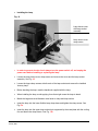
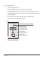
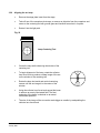
1
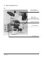
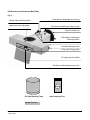
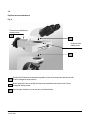
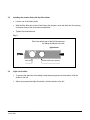
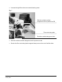
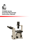
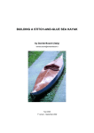
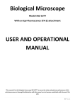
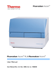
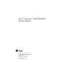
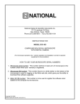
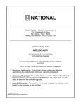
Motic
Episcopic-Fluorescence Attachment EF-UPR-lll
for BA400/BA600
User Manual
Motic Incorporation Ltd.
Prepared by Motic Instruments Inc. Canada
This User Manual has been prepared for users of the
EF-UPR-ll Epi-Fluorescence Attachment used in
conjunction with the Motic BA400-600 Inverted
Microscope.
We are constantly endeavouring to improve our instruments and
to adapt them to the requirements of modern research
techniques and testing methods. This involves modification to
the mechanical structure and optical design of our instruments.
Therefore, all descriptions and illustrations in this instruction
manual, including all specifications are subject to change
without notice.
This manual may not be reproduced or transmitted in whole or in part without Motic’s express
permission.
Motic Instruments Inc. Canada
January 2007
1
Fluorescence
The optical phenomenon that occurs when light absorbed by a material, creates a molecular excitation that
causes the material to re-emit light at a different wavelength.
Fluorescence Microscope for Epi-Fluorescence
The technique of fluorescence microscopy with epi-illuminators (episcopic-illuminator) that is based on
the adaptation of the vertical illuminator used in reflected light microscopy.
The radiation emitted by the light source first passes through the exciting filter and is incident to a shortpass filter* (dichroic beam splitter). The radiation is then reflected into the objective, which also serves
as a condenser.
The objective concentrates the exciting radiation in the object field. Fluorescent light emitted from there,
is collected by the objective and returned in the opposite direction to the short-pass filter, which directs
it into the eyepiece through the barrier filter.
*A filter designed to allow the passage of radiation of wavelengths shorter than a given limit.
Motic Instruments Inc. Canada
January 2007
2
Table of Contents
1.0
Names of Component Parts
2.0
Setting up the Instrument
3.0
Assembly
4.0
Microscopy
5.0
Troubleshooting Table
6.0
Care and Maintenance
Motic Instruments Inc. Canada
January 2007
3
1.0
Names of Component Parts
Fig. 1
Epi - fluorescence
Attachment EF-UPR-lll
Lamphouse for
Mercury Vapour lamp
Light protective shield
UV light shield tube
Power supply unit
Motic Instruments Inc. Canada
January 2007
4
Epi-fluorescence Attachment Main Body
Fig. 2
Shutter slider with filter holder
Observation tube clap screw
Field aperture diaphragm knurled ring
Fluorescence attachment clamp screws
Bayonet clamp ring
Field aperture diaphragm
centering screws
Filter cube cover
Knurled retaining screws
Filter cube ID tag pocket
UV light protective shield
.
Excitation
method change over knob
.
UV Light Blocking Tube
Lamp Centering Tool
System Devices
Motic Instruments Inc. Canada
January 2007
5
2.0
Setting up the Instrument
•
Avoid placing the instrument in areas exposed to dust, vibration, high temperature
and high humidity.
•
Avoid locations exposed to direct sunlight, under room lights.
•
Select location which allows easy access to power cord from products AC inlet
in the event of an emergency.
•
Do not place power supply on a table mat.
Motic Instruments Inc. Canada
January 2007
6
3.0
Assembly
3.1
Microscope assembly
Follow the instructions provided in the microscope manual.
For the purpose of performing simultaneous observation with phase contrast, attach the
appropriate phase contrast components referring to the specific instructions provided.
3.2
Installing the Epi-fluorescence attachment
Please consult the illustrations provided while assembling the attachment
3.3
Required tools
Allen hex keys: 2.5mm and 5mm (supplied with attachment).
Before Starting
Turn off the microscope power switch and unplug the power cord
Motic Instruments Inc. Canada
January 2007
7
3.4
Epi-fluorescence attachment
Fig. 4
Fluorescence attachment
clamp screws
3
2
Eyepiece tube
clamp screw
1
1
Position Epi-fluorescence attachment parallel to the microscope arm and secure with
5.0mm hexagonal clamp screws.
2
Mount eyepiece tube on the Epi-fluorescence attachment and secure with 2.5mm
hexagonal clamp screws.
3
Use the spot stickers to cover the two countersink holes.
Motic Instruments Inc. Canada
January 2007
8
3.5
Installing the shutter slider with the filter holder
•
Loosen one of the slider knobs.
•
With the filter slider slot to the left and facing the operator, insert the slider into the opening
of the main body of the fluorescence attachment.
•
Tighten the loosened knob.
Fig. 5
Block the optical path of the Epi-fluorescence
by sliding the shutter to the left.
Filter slot
3.6
Shutter slider open position
Light cut-off slider
•
To prevent the specimen from fading during temporary pauses in observation, slide the
shutter to the left.
•
When using transmitted light illumination, slide the shutter to the left.
Motic Instruments Inc. Canada
January 2007
9
3.7
Installing the Filter cubes
Caution
•
Always keep four blocks on the slider. Do not leave any of the
filter slots empty as strong light may enter and damage the user’s
eyes when shifting between excitation methods.
•
If fewer than four filter cubes are required for microscopy. Use a
“DIA-ILL” dummy cube to ensure that the open space in the slider
is filled.
•
If the filter slider is not filled with four filter cubes, filter cubes
may shift sideways by the motion of excitation method
changeover movement, UV rays will reach the eyes through an
empty space, causing serious harm.
• Never perform lamp centering with the UV filter cube in the optical
path as harmful UV radiation from the lamp may enter the eyes,
possibly resulting in loss of vision.
•
Remove the filter cube cover
Fig. 6
Knurled retaining screw
Filter cube cover
Motic Instruments Inc. Canada
January 2007
10
•
Unscrew the right filter cube cover knurled retaining screw.
Fig. 7
Slide the excitation method
changeover knob to position four q
q
Filter cube clamp plate
Excitation method changeover knob
•
Slide the excitation method changeover knob to position four q
•
Slacken the filter cube clamp plate hexagonal clamp screw at the end of the filter slider.
Motic Instruments Inc. Canada
January 2007
11
Fig. 8
Excitation method changeover knob
•
While holding the excitation method changeover knob, slide the filter cube into the dovetail
mount of the filter slider.
•
Position the remaining filter cubes using the same procedure so that there are four filter
cubes on the slider.
•
If fewer than four filter cubes are required for microscopy, use a “DIA-ILL” dummy
cube to ensure that the open space in the slider is filled.
Remember the position of the filter cubes for the installation position of the excitation ID tags.
If the filter cubes are to be switched frequently, locate those filter cubes at both ends of the filter
slider.
•
Return the filter cube clamp plate to the horizontal position and tighten the hexagonal clamp
plate clamp screw.
•
Replace the filter cube cover and secure with the knurled retaining screw.
Motic Instruments Inc. Canada
January 2007
12
3.8
Filter cube ID tags
Fig. 9
Filter cube ID tag
ID tag pocket
•
Insert the Filter cube ID tag into the pocket on the front face of the epi-fluorescence
attachment.
•
Select the ID tags showing the excitation method cubes on the slider and drop them into
corresponding pockets.
Motic Instruments Inc. Canada
January 2007
13
3.9
Arrangement of the excitation method ID tags
Fig. 10
Insert ID tag in reverse
order into ID tag pocket
n DIA-ILL
o TRITC
p FITC
q DAPI
n
p
q
X
FITC
DAPI
Positions n
opq
Motic Instruments Inc. Canada
January 2007
o
TRITC
DIA-ILL
show the location of the Filter cube on the filter slider
14
3.10
Attaching UV light protective shield
Fig. 11
Loosen UV light protective shield
Clamp screw under Epifluorescence attachment body
Insert the UV light protective
Shield – slots in from the front
Secure in place with the
clamp screw
3.11
Mounting UV light blocking tube
Fig. 12
Mount UV light blocking tube
on the microscope condenser
carrier and secure in place with
condenser clamp screw
Microscope condenser carrier
Condenser clamp screw
UV light blocking tube
Motic Instruments Inc. Canada
January 2007
15
3.12
Installing the light source
Assembly
Attaching the collector lens to the lamphouse
•
Remove the rubber cap that covers the collector lens focus knob.
•
Loosen the set screw at the base of the focusing knob with a 2.5mm Allen hex key.
•
While pulling out the collector lens focus knob, insert the collector lens into the lamp house
in the direction indicated by insertion arrow.
Fig. 13
Always attach a collector lens to the
lamphouse
This type of collector lens does not
have the ability to cut ultraviolet
rays; the filter cube used during
fluorescence microscopy does
include a method for cutting
ultraviolet rays.
Lamphouse
Collector lens positioning groove
Collector lens
Motic Instruments Inc. Canada
January 2007
16
3.13 Installing the collector lens in the lamp house
•
Aligning the pin on the collector lens, with the collector lens positioning groove of the lamp
house.
Fig. 14
Focus knob pin
Rubber cap
Cheese head
Slotted screw
Collector lens focus knob
Set screw
Collector lens positioning grove
Lamp
this Side
Collector lens focussing grove
Collector lens alignment pin
•
Return the focusing knob to the original position with focus knob pin in focussing groove of
the collector lens.
•
Tighten the set screw at the base of the focusing knob with a 2.5mm Allen hex key.
•
Tighten the cheese-head slotted screw, following lamp alignment and focusing.
•
Affix the rubber cap covering collector lens focus knob.
Motic Instruments Inc. Canada
January 2007
17
3.14
Installing the light source
Attaching the lamp house to the microscope
•
Attach the lamp house to the microscope using the bayonet ring on the Epi-fluorescence
attachment.
Fig. 15
Bayonet ring
Positioning pin
Turn the bayonet ring in
the direction indicated
by the arrow
•
Align the positioning pin on the lamp house flange with
the positioning groove on the bayonet mount of the Epifluorescence attachment
Motic Instruments Inc. Canada
January 2007
18
•
Installing the lamp
Fig. 16
Lamp house cover
with lamp socket
assembly
Lamp house cover
clamp screw
•
In order to prevent electric shock always turn the power switch off, and unplug the
power cord before installing or replacing the lamp.
•
Loosen the lamp house cover clamp screw and remove the cover and the lamp socket
assembly. See Fig. 16
•
Loosen the lamp clamp screws at both ends of the lamp socket and remove the installed
“dummy lamp”.
•
Before handling the lamp, read the handbook supplied with the lamp.
•
When installing the lamp, avoid applying force that might cause the lamp to break.
•
Match the large and small diameter metal ends on lamp and lamp socket.
•
Insert the lamp into the lower flexible lamp clamp base and tighten the clamp screw. See
Fig.17a
•
Insert the lamp into the upper lamp socket hole supported by the metal plate with the cooling
fins and fasten the clamp screw. See Fig. 17b
Motic Instruments Inc. Canada
January 2007
19
Fig. 17a
Lamp house
cover clamp
screw.
Flexible lamp
clamp base
Tab
Fig. 17b
Metal plate with the
cooling fins
•
Insert the bottom tab of lamp house cover over the inner metal surround of the lamp house
and pivot the lamp socket cover to close. Secure with the clamp screw.
•
The safety cut-off micro switch will “click” as you secure the lamp house cover clamp screw.
Motic Instruments Inc. Canada
January 2007
20
3.16
Connecting the lamp house to the power supply:
Turn OFF the power switch on the power supply.
Fig. 18
Input voltage marking
Lamp input connector
AC IN receptacle
3.17
Check the input voltage
•
Confirm that the input voltage marked on the rear panel of the power supply matches your
available line voltage.
•
Use a power cord that is rated for the voltage used in your area and that has been approved
to meet local safety standards. Using the wrong power cord could cause fire or
equipment damage.
•
When using the extension cord, only use a power supply cord with a protective earth (PE)
wire.
•
Plug the lamp input connector into the output connector on the rear panel of the power
supply and secure by tightening the locking ring.
•
Plug in the power cord supplied with the power supply into the AC receptacle on the rear
panel of the power supply.
Motic Instruments Inc. Canada
January 2007
21
3.18
Turning ON the lamp
•
Set the power supply switch to “l”.
•
Press the IGNITION button on the power supply unit for 5-10 seconds.
•
The POWER LAMP / READY LAMP will light up to indicate that the power is turned on.
•
The POWER LAMP / READY LAMP indicator lamp will start flashing briefly to indicate that
the lamp is stabilized.
•
Press the RESET PAD below the RUN TIME counter on the power supply.
•
The “Run Time” counter displays the elapsed time.
Fig. 19
POWER LAMP / READY LAMP indicator
LAMP TIME
0. 0. 0. 0. 0.
H
Reset
M
RUN TIME counter
Counter RESET PAD
IGNITION
IGNITOR button
POWER
POWER switch
I
o
Motic
MHG-100B
Mercury Lamp Power Supply
Motic Instruments Inc. Canada
January 2007
22
3.19
Aligning the mercury arc lamp
DO NOT perform the lamp centering procedure with the UV filter cube in the optical path
as harmful UV radiation from the lamp may enter the eyes, possibly resulting in loss of
vision.
Please note: A UV excitation filter cube cannot be used in this instance since an arc image will
not appear in the window of the centering tool.
It is easier on the eyes to examine the green excitation light radiated by rhodamine filter
cube.
The mercury lamp consists of two electrodes sealed in a glass bulb under high pressure, which
contains mercury. When the power supply is turned on, a high voltage pulse is sent to the
electrodes, which in turn ionize the gas in the bulb, igniting the lamp. These ions, under low
voltage, carry the current that generates the light between the electrodes. The lamp gets very
hot during the vaporization of the mercury; creating high pressure inside the glass bulb.
Avoid applying mechanical force that might cause the lamp to explode.
The average lifetime of a mercury arc lamp varies between 200 and 400 hours, depending upon
design specifications, burns and the switch cycle.
Avoid touching the lamp with bare fingers as the oils from the fingers may etch the glass surface
resulting in light loss.
When the lamp has been allowed to stabilize it gives off high intensity light concentrated at
certain discrete wavelengths (e.g. 365, 400, 440, 546 and 580nm) making it an ideal source of
illumination for fluorescence microscopy.
Motic Instruments Inc. Canada
January 2007
23
3.20
Aligning the arc lamp
•
Remove the stage plate insert from the stage
•
Take off one of the nosepiece dust caps, or remove an objective from the nosepiece and
screw on the centering tool with ground glass and inscribed cross hair in its place.
•
Rotate it into the light path.
Fig. 20
Lamp Centering Tool
•
Centre the lamp while observing the window of the
centering tool.
•
To begin alignment of the lamp, rotate the collector
lens focus knob to produce a sharp image of the arc
on the window of the centering tool.
•
Rotate the lamp horizontal and vertical centering
screws until the arc image is in the centre of the
window.
•
Using the collector lens focus knob spread the beam
to achieve an evenly illuminated field. The final
scattering of the beam is checked on an actual
fluorescent specimen.
•
The size of the image of the arc can be made bigger or smaller by manipulating the
collector lens focus knob.
Motic Instruments Inc. Canada
January 2007
24
3.21
3.22
Changing the size of the field diaphragm
•
The field aperture diaphragm determines the illuminated area on the specimen.
•
Operating the field aperture knurled ring changes the size of the field aperture diaphragm.
For normal observation, the diaphragm is set just slightly outside the edge of the field of
view.
•
If a larger than required area is illuminated, extraneous light will enter the field of view. This
will create a flare in the image and lower the contrast.
•
Cutting out the excessive light is useful in preventing contrast from being diminished.
•
Decreasing excessive illumination is useful in protecting the specimen from fading.
Epi-fluorescence Attachment Main Body
Fig. 21
Field aperture diaphragm
knurled ring
Shutter slider with filter holder
Field aperture diaphragm
centering screws
Motic Instruments Inc. Canada
January 2007
25
3.23
Centering the field diaphragm
•
Move the field aperture diaphragm knurled ring to stop down the diaphragm.
•
If the field aperture diaphragm is off the centre of the field of view, centre the field aperture
diaphragm with centering screws.
•
Open the field aperture diaphragm just slightly outside the edge of the field of view.
Fig. 22
Field aperture diaphragm with
centering screws
Motic Instruments Inc. Canada
January 2007
26
3.24
Adjusting the shutter slider
Whenever observation is interrupted, slide the shutter into the light path by moving the slider to
the extreme left in order to prevent fading of the specimen.
The shutter is also used to cut off the reflected light illumination when observing the specimen
by transmitted light illumination (e.g. as in Phase contrast microscopy).
3.25
Neutral Density Filters
Neutral density filters equally reduce the intensity of all wavelengths of light. These filters are
used for reducing the intensity of the exiting light to prevent photo-bleaching of the specimen.
Relationship between the ND filters and the brightness
Filter
ND2
ND4
ND16
3.26
(T=50%)
(T=25%)
(T=6.25%)
Heat absorbing filter
The heat-absorbing filter is placed in front of the light source to reduce heat transfer to the
excitation filter, and damage to the interference filter coatings.
When utilizing the infrared excitation method remove the heat-absorbing filter, as it will not
transmit the near infrared and infrared light.
3.27
Filter Blocks
A cube shaped modules that hold a matched set of fluorescence filters including excitation (EX),
barrier-emission (BA) and a dichroic mirror (DM).
The excitation filter allows transmission of light at a wavelength within the absorption spectrum
of the dye and rejects light at wavelengths within the emission spectrum of the dye, which could
be reflected by the specimen and incorrectly detected as emission energy.
A barrier filter allows the transmission of light at wavelengths within the emission spectrum of
the dye and rejects light at wavelengths within the absorption spectrum of the dye, which could
be detected as emission energy.
A dichronic mirror is placed at a 45º angle relative to the incoming excitation light; the dichroic
mirror performs two functions: it reflects the shorter wavelength exciting radiation light to the
specimen and transmits the longer wavelength fluorescence.
Motic Instruments Inc. Canada
January 2007
27
4.0
Microscopy
Epi-fluorescence Micoscopy
4.1
Selecting fluorescence filters:
For best results, select excitation and emission filters with centre wavelengths as close to the
absorption and emission peaks as possible.
Note: The centre wavelength is situated at the midpoint of the bandwidth. It is not necessarily
the peak transmission wavelength although with a symmetrical band the centre wavelength and
the peak wavelength are equal.
4.2
Selecting excitation filters (EX)
Excitation filters selectively pass the light within the range of wavelengths needed to cause the
specimen to fluoresce and filter out other light.
To maximize the brightness of the desired fluorescence (the signal) relative to brightness of the
background (the noise), one can choose excitation and emission filters with wide bandwidths.
However this may result in unacceptable overlap of the emission signal with the excitation
signal, resulting in poor resolution and wide bandwidth which also leads to a high level of selffluorescence and severe fading.
To minimize spectral overlap, one can instead choose excitation and emission filters that are
narrow in bandwidth and are spectrally well separated to increase signal isolation. This will
conversely yield a dark image. Since little excitation light reaches the specimen, selffluorescence and fading are minimal.
4.3
Selecting barrier filters (BA)
The barrier filter prevents the excitation light from reaching the observers eye. Its transmission
should be as low as possible in the range of light used for excitation, and as high as possible
within the spectral range of the emission from the specimen.
Barrier filters may be Longpass (LP) or Bandpass (BP).
Motic Instruments Inc. Canada
January 2007
28
4.3.1
Longpass
Longpass filters only allow wavelengths above a
certain wavelength to pass through and will prevent
light of lower wavelength from passing through.
Block
Longpass filters should be used when the
application requires maximum emission and
spectral differentiation is not necessary. This is
generally the case for fluorophores that generate a
single emitting species in specimens with
reasonably low levels of background auto
fluorescence.
Pass
Longpass Filter
Fluororophore or fluorescent probe:
Fluorochromes when conjugated to other originally active substances, such as a protein,
antibody, or nucleic acid, in order to selectively stain targeted substances within the specimen
Longpass filters are also useful for observing all the stains on multi-stained specimen such as
FITC and TRITC .
4.3.2
Band pass
Filters that pass light of a certain restricted range of wavelength.
Bandpass filters are useful for observing a certain stain on multi-stained specimen such as
when two stains FITC and TRITC are used.
Bandpass filters are designed to maximize the brightness of the desired fluorescence (signal) to
brightness of the background (the noise) ratio for applications where discrimination of signal
component is more important than overall image brightness.
Block
Block
Block
Pass
Block
Pass
Narrow Bandpass Filter
Motic Instruments Inc. Canada
January 2007
Wide Bandpass Filter
29
FITC
FITC
TRITC
Both FITC and TRITC are visible
Only FITC is visible
Selecting fluorescence filters requires a thorough understanding of filter technology. This will
enable the user to utilize stain and illumination selection to improve the image quality of the
desired fluorescence signal.
Selection of filter combinations also requires knowledge of the excitation and emission spectra
of the stain.
Epi-fluorescence and Phase Contrast Microscopy
In addition to epi-fluorescence microscopy, phase contrast microscopy can be used to search
an organelle or the location of a particular molecule in a cell instead of epi-fluorescence
microscopy which bleaches the specimen.
Combing epi-fluorescence microscopy with phase contrast microscopy makes it possible to
compensate for the limitations of each method.
4.4
Using an oil immersion objective
Oil immersion objectives are labelled with the additional engraving “Oil” and are to be immersed
in oil between the specimen and the front of the objective.
The immersion oil supplied by Motic is synthetic, non-fluorescing and non-resining oil, with a
refractive index of 1.515
Normally, a cover glass must be used with oil immersion objectives with a few exceptions.
Deviations from thickness are not important as a layer of immersion oil acts as compensation
above the cover glass.
The small bottle of oil supplied with every immersion objective facilitates application of the oil to
the cover slip.
Remove any air bubbles in the nozzle of the oil container before use.
Immersion oil must be used sparingly.
Motic Instruments Inc. Canada
January 2007
30
Freedom from air bubbles must be ensured. To check for air bubbles, remove one eyepiece,
open the field diaphragm as far as possible and look at the exit pupil of the objective within the
eyepiece tube (the exit pupil will appear as a bright circle).
If it is difficult to see if there are any bubbles, use a phase centering telescope and rotate the
eyepiece part of the centering telescope to focus on the exit pupil of the objective. Air bubbles in
the oil will deteriorate the specimen image. To purge bubbles, swing the immersed objective
forward and backwards by rotating the revolving nosepiece, add more oil, or wipe off the oil and
apply new oil.
Place a single drop of immersion oil on the cover glass.
Make contact with the cover glass, and focus.
View and wipe clean the objective with a lens cleaning tissue.
Any residual film of oil remaining on immersion type objective, or where it has spread to the
surface of dry type objective will have a discernible, negative effect on the image.
To remove a film of oil, moisten a lens tissue or clean cloth with petroleum benzine and lightly
wipe the lens surface, wipe the lens surface with absolute alcohol (ethyl alcohol or methyl
alcohol).
Petroleum benzine and absolute are highly inflammable. Use great care when handling them.
4.5
Fluorescence Photomicrography
For the basic procedure and key points of photomicrography, see the manuals provided with the
photomicrographic equipment
Since the specimen colour may fade effort must be made on minimizing the exposure of the
specimen to irradiation both before, and during exposure.
Select the area of interest without using fluorescence, use phase contrast or interference
contrast.
Select an appropriate filter combination for the specimen (whether single, dual or triplepass filter
sets are used, exposure times for acquiring video or photographic images will increase for dual
and triplepass filter sets when compared to singlepass filter sets).
The magnification of the image at the film plane affects the intensity of the image; the latter is
inversely proportional to the magnification. To minimise the magnification required to fill the
picture with the desired object, the format chosen should be as small as considered practical
and hence have shorter exposure times.
Exposure time varies for each objective and projection lens combination even if the total
magnifications are the same. The objective with higher numerical aperture (N.A.) should be
chosen over increasing the magnification by projection lens. (The numerical aperture of the
Motic Instruments Inc. Canada
January 2007
31
objective increases with increase in magnification and higher the numerical aperture, the
brighter the image).
Excessively bright excitation light will cause the specimen to fade, adjust the brightness by
inserting a neutral density filter in the light path as these filters give a constant transmission over
a wide range of wavelengths.
Focus collector lens give brighter or more even illumination.
Avoid bleaching of the specimen by blocking the excitation light when not viewing or
photographing the specimen.
4.6
Video Fluorescence Microscopy
Electronic photomicrography utilizes electronic detection devices to acquire images, inserting an
IR (infrared) barrier filter in the light path before the detection device may produce better results
by avoiding erroneous readings caused by infrared light.
Motic Instruments Inc. Canada
January 2007
32
5.0
Troubleshooting Table
As you use your microscope and the epi-fluorescence attachment, you may occasionally
experience a problem.
The troubleshooting table below contains the majority of frequently encountered problems and
the possible causes.
Electrical
Lamp does not light
Power supply not plugged in.
Lamp not installed.
Lamp burnt out.
Fuse is blown.
Inadequate brightness
Lamp blows out immediately
Specified lamp not being used.
Specified lamp not being used.
Lamp flickers
Connectors are not securely connected
Lamp near end of service life.
Lamp not securely plugged into socket.
Optical
Image not visible
Lamp on but image is unclear
or has no contrast
Field of view is partially obscured
Motic Instruments Inc. Canada
January 2007
Shutter slider in light path.
Filter cube unsuitable for specimen.
Filter cube not completely in light path.
Light source is not centred.
ND filter in optical path.
Filter cube unsuitable for specimen.
One component of filter cube is missing.
Objective or filters are dirty.
Specimens slide or cover glass dirty.
Slide glass is fluorescing.
Cover glass is missing.
Greasy residue on eyelens.
Room light is too bright.
Revolving nosepiece not clicked into position.
Shutter slider in intermediate position.
Filter cube not installed correctly.
Filter cube in intermediate position.
Field diaphragm out of centre.
Field diaphragm is stopped down
33
6.0
Care and Maintenance
6.1
Lenses and filters
6.2
6.3
•
To clean lens surfaces or filters, first remove dust using an air blower. If dust still persists,
use a soft/clean brush or gauze.
•
A soft gauze or lens tissue lightly moistened with pure alcohol should only be used to
remove grease or fingerprints.
•
Use petroleum benzine to clean immersion oil.
•
Use petroleum benzine only to remove immersion oil from objective lenses.
•
Because petroleum benzine and absolute alcohol are both highly flammable, be careful
handling around open flame.
•
Do not use the same are of gauze or tissue to wipe lens more than once.
Cleaning or painted or plastic components
•
Do not use organic solvents (thinners, alcohol, ether etc.) doing so could result in
discoloration or in the peeling of paint.
•
For stubborn dirt, moisten a piece of gauze with diluted detergent and wipe clean.
When not in use
•
When not in use, cover the instrument with vinyl dust cover and store in a place low in
humidity where mold is unlikely to form.
•
Store the objectives, eyepieces and filters in a container or desiccator with drying agent.
Proper handling of the microscope will ensure years of trouble free service. If repair becomes
necessary, please contact your Motic agency or our Technical Service directly.
Motic Instruments Inc. Canada
January 2007
34
Fluorescence Filter Cubes (Ø 25mm Series).
The fluorescence vertical illuminator can accommodate three filter blocks and a dia-filter
dummy block (devoid of filters) that enables normal brightfield observation. Filter blocks are
mounted on a slider inside the Epi-fluorescence attachment and can be inserted into the optical
path by means of the excitation method change over knob. Each block has an accompanying ID
tag that can be inserted into a pocket on the illuminator exterior housing in sequential order to
enable the operator to easily select the proper block for fluorescence observation.
The excitation filters deteriorate with time due to exposure to heat and intense light.
Replace when necessary.
Handle Multi- Band filters with great care as the very complex coatings wear easily.
Special attention should be given to moisture. When filter is not in use, store in a
desiccator.
Motic Instruments Inc. Canada
January 2007
35
Motic
Standard Fluorescence Filter Sets
MF31000
DAPI and Hoechst Set:
Exciter D350/50x
Dichroic 400DCLP
Emitter D460/50m
MF31001
FITC FITC/RSGFP/Fluo 3/DiO Acradine Orange(+RNA) set:
Exciter D480/30x
Dichroic 505DCLP
Emitter D535/40m
MF31002
TRITC (Rhodamine)/DiI/Cy3 Set:
Exciter D540/25x
Dichroic 565DCLP
Emitter D605/55m
MF31004
Texas Red® / Cy3.5 Set:
Exciter D560/40x
Dichroic 595DCLP
Emitter D630/60m
MF41008
Cy5, Alexa Fluor 633, Alexa Fluor 647 Set:
Exciter HQ620/60x
Dichroic Q660LP
Emitter HQ700/75m
MF31044
The emission at these wavelengths will be better detected by camera than by the
unaided eye. Only a small percentage of humans can detect these wavelengths.
Cyan GFP Set:
Exciter D436/20x
Dichroic 455DCLP
Emitter D480/40m
This set will typically exclude the signal from YFP but not from GFP.
MF41017
Endow GFP Bandpass Emission Set:
Exciter HQ470/40x
Dichroic Q495LP
Emitter HQ525/50m
This is the recommended filter set for the newer S65T GFP mutants. It is also
recommended for wtGFP for which it was originally designed.
Motic Instruments Inc. Canada
January 2007
36
MF41028
Yellow GFP BP (10C/Topaz) Set:
Exciter HQ500/20x
Dichroic Q515LP
Emitter HQ535/30m
This set is designed to image YFP. It will not, in most cases, detect CFP when coexpressed in cells. By eye, fluorescence in the 535 nm pass-band will be seen as
green.
Motic Instruments Inc. Canada
January 2007
37
Arrangement of Filters in a Fluorescence Cube
Upright Microscope
To Observation Method
Barrier (Emission Filter)
Dichroic Mirror
(Beamsplitter)
Excitation
Filter
To Objective and Specimen
It is often the case that specific combinations of excitation filter, emission filter and dichroic mirror are
needed to visualize and/or quantitate the fluorescence emission from a particular fluorescent species.
In newer models of fluorescence microscopes, manufacturers have provided a means to change these
optical elements in a convenient manner by arranging a set of four or more filter cubes in a circular (or
linear) turret under the objective. With a turret arrangement, a specific filter cube can be selected in a
manner similar to that of selecting a specific objective.
Motic Instruments Inc. Canada
January 2007
38
NOMENCLATURE
Excitation Filter - EX
A filter used in fluorescence microscopy designed to pass only those wavelengths, which excite
fluorescence.
Excitation Filter D350/50x
The center wavelength is at 350nm; full bandwidth is 50nm [= ±25nm].
In some cases when the bandwidth is not specified, the letter ”x” is used to define the filter as an exciter
filter and is generally used for narrow band UV excitation filters, e.g. D350x.
Dichroic Mirror - DM
The dichroic mirror is the optical component that separates the excitation light from the fluorescence.
Dichroic mirror is designed to reflect selectively the shorter wavelength exciting radiation and transmit
the longer wavelength fluorescence.
Dichroic mirror are placed in a 45° incidence angle to light, allowing the mirrors to act as a precise
discriminator of excitation and fluorescence wavelengths.
Light passing through the excitation filter is reflected 90° toward the objective and the specimen.
Finally, light emanating from the specimen is passed through and directed toward the emission filter
and observation method.
Dichroic multi-layer thin-film coatings makeup typically consists of one of the following design types:
short wave pass, long wave pass, or bandpass filter. These design types comprise the basis of color
determination and color separation and this is determined by the transmittance and/or reflectance of a
band of wavelengths.
Dichroic Beamsplitter 505DCLP
The cut-on wavelength is approximately 505nm for this dichroic longpass application.
Emission Filter - EM (Barrier filter)
Emission filter is the last component in a fluorescence cube, which transmits fluorescence emission
wavelengths while blocking excitation wavelengths. Emissions filters are coloured glass or interference
filters that have transmission properties of a bandpass or longpass filters.
Most interference are mounted at a slight angle to allow for better imaging by suppressing ghost
images.
Emission filter D460/50m*
The center wavelength is at 460nm; full band is 50nm [= ±25nm].
*m –emission
Motic Instruments Inc. Canada
January 2007
39
DEFINITIONS OF FILTER TERMINOLOGY
Bandpass Filters
Bandpass filters transmit a band of wavelengths and block all light above and below the specified
transmission range. These filters are characterized with respect to optical performance by their centre
wavelength (CWL) and bandwidth, also referred to as the full width at half of maximum transmission
(FWHM). (See Figure Below)
CWL
Center wavelength
For optical bandpass filters, the arithmetic mean of the cut-on and cut-off wavelength at 50% of peak
transmission.
DCLP
Dichroic Longpass.
DCXR
Dichroic Longpass, extended reflection including the UV.
FWHM
Bandpass filters are usually named by their filters center wavelength (the arithmetic means of the
wavelengths at 50% of center peak transmission) and by range of wavelengths (bandwidth) of light they
transmit at 50% peak transmittance (full width half maximum, FWHM). Example D350/50x is an
interference filter with maximal transmission at 350nm and transmits light from 325 and 375nm. (See
Figure Below)
GFP
The Green Fluorescent Protein (GFP) from the jellyfish Aequorea victoria is used as a fluorescent
indicator for monitoring gene expression in a variety of cellular systems, including living organisms and
fixed tissues.
The wild type GFP has a major excitation peak at a wavelength of 395 nm and a minor one at 475 nm.
Its emission peak is at 509 nm which is in the lower green portion of the visible spectrum.
Due to this widespread usage different mutants of GFP have been engineered over the last few years:
Color mutants have been obtained from the GFP gene as well: in particular the cyan fluorescent
protein (CFP) and the yellow fluorescent protein (YFP) are two colour variants employed for
fluorescence resonance energy transfer (FRET) experiments.
GG
Green Glass – Longpass absorption glass from Schott Glassworks with cut-on wavelengths in the violet
and blue-green regions
HQ
A designation for high-performance filters with narrow cuton and cutoff wavelengths
Motic Instruments Inc. Canada
January 2007
40
LP
Longpass Filters
Longpass filters transmit a wide spectral band of long wavelength radiation while blocking short
wavelength radiation. (See Figure Below)
Narrowband Filters
Narrowband filters with a very narrow band, typically 1 to 3nm wide. They can be used successfully
only with high intensity light sources because of the narrow bandwidth.
ND
Neutral density filters are designed to reduce transmission evenly across a portion of the spectrum.
OG
Orange Glass - Longpass absorption glass from Schott Glassworks with cut-on wavelengths in the
green, yellow and orange regions
PC
Polychromatic mirrors or beamsplitters.
These beamsplitters reflect and transmit more than two bands of light. Dual-band or Triple-band filter
sets includes three carefully balanced combinations that contain dual or triple bandpass excitation and
emission filters, these dedicated filter sets also incorporate polychromatic mirrors or beamsplitters with
multiple bandpass characteristics, having transmission and reflection regions that are matching to the
specific excitation and emission filters employed.
RG
Red Glass - Longpass absorption glass from Schott Glassworks with cut-on wavelengths in the red and
far red regions
SP
Shortpass Filters
Shortpass filters transmit a wide spectral band of short wavelength radiation and block long wave
radiation. (See Figure Below)
S/N
Signal to Noise Ratio
Ratio of intensity of signal to that of the background.
Stokes shift
The distance between the peak absorption and emission of a dye, usually in nm.
Motic Instruments Inc. Canada
January 2007
41
Filters for isolating the wavelength of illumination:
Shortpass and longpass filters, block or transmit wavelengths at specific cut-off wavelengths.
Bandpass filters exhibit broadband or shortband transmission centered on a particular band of
wavelengths. Filters performance is defined by the central wavelength (CWL) and by the full width at
half maximum (FWHM).
Motic Instruments Inc. Canada
January 2007
42
Motic Instruments Inc.
Richmond
British Columbia
Canada
January 2, 2007
Motic Instruments Inc. Canada
January 2007
43