1
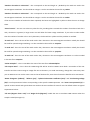
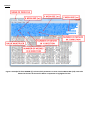
“Number of meshes in Y direction” - this corresponds to the total length in y divided by the mesh size used in the
micromagnetic simulation. This should be an integer. It is also recorded in the text file as ynodes.
“Number of meshes in Z direction” - this corresponds to the total length in z divided by the mesh size used in the
micromagnetic simulation. This should be an integer. It is also recorded in the text file as znodes.
If the incorrect number of meshes has been inputted, the boxes are highlighted in yellow to alert the user to change
them.
“Size of matrix” – the user can select any value for this, providing that it exceeds the number of meshes in both the x
and y directions. In general, a larger matrix size will allow for better image simulation. If you select a value smaller
than the number of meshes in the x and y directions, the box will turn yellow until the problem is rectified.
“X mesh size”- this is the size of the mesh used in the x direction in the micromagnetic simulation. Ideally this should
be small for optimal image simulating. It is also recorded in the text file as xstepsize.
“Y mesh size”- this is the size of the mesh used in the y direction in the micromagnetic simulation. Ideally this should
be small for optimal image simulating. It is also recorded in the text file as ystepsize.
“Z mesh size”- this is the size of the mesh used in the y direction in the micromagnetic simulation. It is also recorded
in the text file as zstepsize.
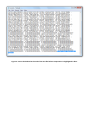
“Value multiplier” – this is recorded at the start of the text file as valuemultiplier.
“File output name” – this is what the LTEM image file will be saved as. MALTS saves both a screenshot of the user
interface and the Lorentz image as image files into its directory. To avoid overwriting, change this name every time
you run MALTS. Do not use the same name as that of the data file, since this will cause the data file to be overwritten.
“Beam divergence (radians)”, “defocus (µm)”, “spherical aberration coefficient (mm)” and “accelerating voltage
(kV)” are all experimental values corresponding to the specific LTEM experiment. The “mean inner potential (V)” is
specific to the material and typical values are cited on the user interface for ease of use. The default values are typical
experimental values.
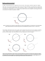
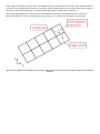
“Tilt axis (degrees from x axis)” and “Angle of tilt (degrees)” enable the user to simulate LTEM contrast when the
sample is tilted (see Figure 2).