1
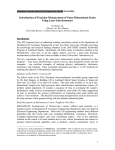
7N
Agilent 10735A, 10736A, and
10736A-001 Three-Axis
Interferometers
Chapter 7N Agilent 10735A, 10736A, and 10736A-001 Three-Axis
Interferometers
Description
Description
The Agilent 10735A and Agilent 10736A Three-Axis interferometers
(see figures 7N-1 and 7N-2, respectively) provide three parallel
interferometers in a single housing. They allow up to three
measurements (displacement, pitch, yaw) to be made on a single axis.
The Agilent 10735A and Agilent 10736A interferometers are identical
except for their measurement beam patterns.
The Agilent 10736A-001 interferometer (see Figure 7N-3) is identical
to the Agilent 10736A interferometer, except that its Measurement
Axis #2 beam paths are bent at right angles away from its other
measurement axis paths.
These interferometers are designed to use a 9 mm diameter laser
beam, available from an Agilent 5517C-009 Laser Head.
Smaller-diameter laser beams can be used, but the usable angle range
is reduced. Agilent 10725A 50% Beam Splitters and Agilent 10726A
Beam Benders are available for use in delivering the beam from the
laser head to the interferometer. Agilent 10780F, E1708A, or E1709A
remote receivers are used at the Agilent 10735A’s laser output
apertures.
The measurement beam parallelism inherent in the design of the
Agilent 10735A and Agilent 10736A interferometers ensures that there
is essentially no cosine error between their three measurements and
also ensures angle accuracy for pitch and yaw measurements. The
Agilent 10736A-001 interferometer has the same parallelism
characteristic for its two parallel measurement axes.
These interferometers are designed for direct attachment of
Agilent 10780F, E1708A, or E1709A remote receiver fiber-optic sensor
heads (one per axis). This simplifies user assembly, since no optical
alignment of the receiver is required. The three fiber-optic receiver
sensor heads are attached directly to apertures on the same face of the
interferometer as the input aperture.
The optics of each of these interferometers are factory-aligned to
predetermined mounting surfaces on the interferometer’s housing.
This simplifies user installation and alignment of the interferometer in
the measurement system.
These interferometers are of the same type of high-stability plane
mirror interferometer design as the Agilent 10706B interferometer.
7N-2
User’s Manual
Chapter 7N Agilent 10735A, 10736A, and 10736A-001 Three-Axis
Interferometers
Description
AGILENT 10735A THREE-AXIS INTERFEROMETER
Int
er
fer
is
fer
o
6A
te
me
is
x
3A
er
Int
73
r
x
3A
10
To Measurement Mirror
om
10
ete
73
r
5A
See
View B
See
View A
Axis #3
Not Used
Input for all Axes
Axis #3
Output
Do not loosen
these (or any)
screws
Axis #1
Output
Primary
Beams
Axis #2
Output
Axis #1
View A
INPUT FACE
Axis #2
View B
MEASUREMENT FACE
Figure 7N-1. Agilent 10735A Three-Axis Interferometer
User’s Manual
7N-3
Chapter 7N Agilent 10735A, 10736A, and 10736A-001 Three-Axis
Interferometers
Description
AGILENT 10736A THREE-AXIS INTERFEROMETER
10
fe
Int
er
5A
ete
r
xis
3A
er
fer
To Measurement Mirror
om
10
3A
Int
xis
73
m
ro
ete
73
r
6A
See
View B
See
View A
Axis #3
Not Used
Input for all Axes
Do not loosen
these (or any)
screws
Axis #3
Output
Axis #1
Output
Primary
Beams
Axis #2
Output
Axis #1
View A
INPUT FACE
Axis #2
View B
MEASUREMENT FACE
Figure 7N-2. Agilent 10736A Three-Axis Interferometer
7N-4
User’s Manual
Chapter 7N Agilent 10735A, 10736A, and 10736A-001 Three-Axis
Interferometers
Description
AGILENT 10736A-001 THREE-AXIS INTERFEROMETER
PRODUCT EQUIPPED WITH
er
fer
er
Int
Int
fer
is
o
OPTION 001
5A
te
me
is
x
3A
73
r
x
3A
10
To Measurement Mirror
om
10
ete
73
r
6A
See
View B
See
View A
Axis #3
Not Used
Input for all Axes
Do not loosen
these (or any)
screws
Axis #3
Output
Primary
Beams
Axis #2
Output
Axis #1
Output
Axis #1
View A
INPUT FACE
Axis #2 (Bent Axis)
View B
MEASUREMENT FACE
Figure 7N-3. Agilent 10736A-001 Three-Axis Interferometer
Applications
General
The Agilent 10735A or Agilent 10736A interferometer, by making
three simultaneous distance measurements along or parallel to the
X-axis, can make these measurements:
•
displacement along the X-axis
•
rotation (pitch) about the Y-axis
•
rotation (yaw) about the Z-axis
Because it has only two parallel measurement axes, the
Agilent 10736A-001 can make the displacement measurement and one
angular measurement.
User’s Manual
7N-5
Chapter 7N Agilent 10735A, 10736A, and 10736A-001 Three-Axis
Interferometers
Description
MEASUREMENT USING AGILENT 10735A AND
AGILENT 10736A-001 INTERFEROMETERS
Laser Head
Beam
Directing
Optics
Agilent
g
10735A
A
Three-Axis
Interferometer
To Fiber Optics
Receivers
Agilent
g
10736A-001
Three-Axis Interferometer
To Plane Mirror
(Auxiliary Measurement)
Multiaxis
Stage
To Fiber Optics
Receivers
Figure 7N-4. Measuring Using Agilent 10735A and Agilent 10736A-001 Interferometers
The angular measurements made by any of these interferometers can
be calculated by taking the arctangent of the differences between two
linear measurements involved, divided by their separation:
Y – Y’
THETA = arc tan -------------D
This method for determining angle is described in more detail under
the “Electronic yaw calculation method” and “Optical yaw calculation
method” subsections under the “Three-axis system using discrete plane
mirror interferometers (X, Y, YAW)” section in Chapter 3, “System
Design Considerations,” of this manual.
X-Y stage
These interferometers are well suited for X-Y stage or multiaxis
applications, such as lithography equipment. One Agilent 10735A or
Agilent 10736A interferometer, used with any other one of these
three-axis interferometers, can measure all X, Y, pitch, roll, and yaw
motions of a stage. In these applications, the measurement mirrors are
attached to the X-Y stage.
7N-6
User’s Manual
Chapter 7N Agilent 10735A, 10736A, and 10736A-001 Three-Axis
Interferometers
Description
MEASUREMENT PATH (fB)
Reference
Mirror
Agilent 10735A and Agilent 10736A
Three-Axis Interferometers
Axis #1
From
Laser
fB
Axis #2
Axis #1 = f B±2 ∆f 1
Axis #2 = f B±2 ∆f 2
Axis #3 = f B±2 ∆f 3
Axis #3
λ/4 Plate
NOTE: Because the Measurement
mirror may have a combination of
displacement, pitch, and yaw motions,
the Measurement Axes may have
different Df values, as shown
Measurement
Mirror
REFERENCE PATH (fA)
Reference
Mirror
Agilent 10735A, Agilent 10736A, and Agilent 10736A-001
Interferometers
Axis #1
From
Laser
fA
Axis #2
Axis #1 = f A
Axis #2 = f A
Axis #3 = f A
Axis #3
λ/4 Plate
Measurement
Mirror
COMPOSITE (f A) and (f B)
Reference
Mirror
Agilent 10735A and Agilent 10736A
Three-Axis Interferometers
Axis #1
From
Laser
Axis #2
Axis #3
Axis #1 = fB±2 ∆ f1, fA
Axis #2 = fB±2 ∆ f2, fA
Axis #3 = fB±2 ∆ f3, fA
λ/4 Plate
Measurement
Mirror
LEGEND
= fA
=
= fB
= fA and f B
Rounded corners are used to help you trace paths.
Figure 7N-5A. Agilent Three-Axis interferometers — beam paths
User’s Manual
7N-7
Chapter 7N Agilent 10735A, 10736A, and 10736A-001 Three-Axis
Interferometers
Description
MEASUREMENT PATH (fB)
Agilent 10736A-001
interferometer
Reference
Mirror
Axis #1
f
From B
Laser
Axis # 2
Axis #3
Axis #1 = fB±2 ∆f1
Axis # 2 = fB±2 ∆f2
Axis #3 = fB±2 ∆f3
λ/4 Plate
NOTE: Because the Measurement
mirror may have a combination of
displacement, pitch, and yaw motions,
the Measurement Axes may have
different Df values, as shown
Measurement Mirror
Measurement Axis # 2
Measurement Mirror
Measurements Axes #1 and #3
LEGEND
= fA
=
= fB
= fA and fB
Rounded corners are used to help you trace paths.
Figure 7N-5B. Agilent Three-Axis Interferometers — beam paths (continued)
Optical Schematics
Optical schematics for these interferometers are given in
figures 7N-5A and 7N-5B. Each interferometer functions similarly to
three parallel Agilent 10706B High Stability Plane Mirror
Interferometers with a three-way beam splitter in front of them.
To reduce thermal drift errors, the measurement and reference beam
paths have the same optical path length in glass. This minimizes
measurement errors due to temperature changes in the interferometer.
7N-8
User’s Manual
Chapter 7N Agilent 10735A, 10736A, and 10736A-001 Three-Axis
Interferometers
Special Considerations
Special Considerations
Laser beam power consideration
When working with an application that requires use of a separate
beam splitter, make sure that you provide enough laser beam power to
any multiaxis interferometer so all receivers connected to it receive
adequate light power. This will help ensure that each measurement
receiver in the system receives the optimum signal strength in the
intended application.
9-mm laser beam considerations
These interferometers are designed to use a 9-mm laser beam.
The 9-mm beam is available from an Agilent 5517C-009 Laser Head.
For more information about this laser head, see Chapter 5, “Laser
Heads,” in this manual.
Most Agilent beam-directing optics are designed for use with a 6-mm
laser beam. For use in 9-mm installations, Agilent offers the
Agilent 10725A Laser Beam Splitter and the Agilent 10726A Laser
Beam Bender. These two optical devices do not include a housing or
mounting hardware. For these optics, the user must devise mounts
that will hold the required optics in position without causing stress
that may distort the optic.
The recommended receiver for the 9-mm beam is an Agilent 10780F
Remote Receiver.
The standard Agilent 10780C Receiver input aperture is designed for
use with a 6-mm laser beam, so this receiver is not recommended for
use in a 9-mm laser system.
Using a 6-mm laser source allows use of standard Agilent 10700A,
Agilent 10701A, and Agilent 10707A beam-directing optics, and use of
Agilent 10710B Adjustable Mounts; however, this also reduces the
usable angle range.
Orientation
Note that although illustrations may show the interferometer in one
orientation, you may orient the unit as required by your measurement
application — vertically, horizontally, or upside-down.
User’s Manual
7N-9
Chapter 7N Agilent 10735A, 10736A, and 10736A-001 Three-Axis
Interferometers
Mounting
Mounting
General
Before any of these interferometers are installed, a suitable mounting
location must be prepared for it.
These are “referenced” interferometers; this means that the
relationships of their internal optical components and laser beam
paths to reference locations on their bases are specified. These
dimensions are presented in the “Specifications and Characteristics”
section at the end of this subchapter and in Figure 7N-6. The
specifications, plus the information in this subsection, are intended to
allow you to select, design, and build a mounting location for a
three-axis interferometer. The interferometer’s mounting location
defines the relationship of its measurement beams to the stage whose
motion is to be measured. Figure 7N-7 shows a recommended design
for the interferometer’s mounting location.
Kinematic mounting should be used. This means that the
interferometer’s mounting location is completely defined by a plane, a
line, and a point.
The mounting plane is identified as datum A. It should be parallel to
the plane of the X and Y axes of the stage being measured.
7N-10
User’s Manual
Chapter 7N Agilent 10735A, 10736A, and 10736A-001 Three-Axis
Interferometers
Mounting
AGILENT 10735A THREE-AXIS INTERFEROMETER
Axis #3
MP3, Z-Axis
See Notes 1 & 2
Not Used
FROM
LASER
HEAD
21.0
(0.83)
Axis # 1
Datum
C
62.17
(2.45)
Axis # 2
26.0
(1.02)
13.11
(0.52)
Datum
A
MP1
See Note 1
See Note 3
26.22
(1.03)
MP2
See Note 1
AGILENT 10736A THREE-AXIS INTERFEROMETER
Axis #3
MP3, Z-Axis
See Notes 1 & 2
FROM
LASER
HEAD
21.0
(0.83)
Datum
C
75.28
(2.96)
Axis # 1
Axis # 2
Not Used
26.0
(1.02)
13.11
(0.52)
Datum
A
MP1
See Note 1
See Note 3
26.22
(1.03)
MP2
See Note 1
AGILENT 10736A-001 THREE-AXIS INTERFEROMETER
Axis #3
MP3, Z-Axis
See Notes 1 & 2
Datum
C
75.28
(2.96)
Not
Used
FROM
LASER
HEAD
21.0
(0.83)
Axis # 1
26.0
(1.02)
Datum
A
See Note 3
Axis # 2
(Bent Axis )
GENERAL NOTES:
1. For Each Axis:
Darker Beam
Indicates
Primary Beam.
Measurement
Beams
MP = Measurement Point
2. Suggested Position for Z-Axis
Plane of Measurement is Axis #3
Measurement Point (MP3).
MP1
See Note 1
3. Datum A (bottom of corner feet).
4. Drawing not to scale.
Figure 7N-6. Three-Axis interferometers — beam patterns
User’s Manual
7N-11
Chapter 7N Agilent 10735A, 10736A, and 10736A-001 Three-Axis
Interferometers
Mounting
TO MEASURMENT MIRROR
-C-
190 mm
(7.48)
170 mm
(6.69)
10.0 mm
(0.39)
3 Pins X 4 mm Dia (0.16)
Max Height < 5 mm (0.20)
A
A1
4.0 mm
(0.16)
2.0 mm
(0.08)
Datum
B
A2
2X 8.0 mm
(0.31)
-B47.5 mm
(1.87)
2.0 mm
(0.08)
15.0 mm
(0.59)
88.5 mm
(3.48)
105.0 mm
(4.13)
FROM
LASER
HEAD
179 mm
(7.04)
5.5 mm
(0.22)
4X φ 6.0 mm Dia Thru
(0.24)
or
4X M5 Threaded Hole
A
11.0 mm
(0.43)
A
11.0 mm
(0.43)
A3
A4
0.4
0.2
-A-
SECTION A-A
Figure 7N-7. Three-Axis interferometer — mounting
The line of the interferometer’s mounting location is identified as
datum B. It lies in datum A, and should be parallel to the surface of the
stage mirror being measured. Physically, the datum B line is created
by placing two dowel pins in the surface that forms the datum A plane.
The point of the interferometer’s mounting location is identified as
datum C. It establishes a specific installation location for the
interferometer along the line of datum B. Physically, the datum C
point is created by placing a single dowel pin in the surface that forms
the plane of datum A.
7N-12
User’s Manual
Chapter 7N Agilent 10735A, 10736A, and 10736A-001 Three-Axis
Interferometers
Mounting
NOTE
Although the general mounting arrangements for Agilent 10735A,
Agilent 10736A, and Agilent 10736-001 interferometers are similar,
they are not the same. The relation of their measurement beam
patterns to the alignment point datum C are slightly different. An
Agilent 10736A or Agilent 10736-001 interferometer installed in a
mounting location designed for an Agilent 10735A interferometer (or
vice-versa) may not give exactly the same results.
One important consideration in determining interferometer placement
is the relationship of the interferometer’s beam pattern to the
coordinate origin of the system you want to measure. See Figure 7N-6.
Looking at the interferometer’s measurement aperture face, the
coordinate origin should be aligned with the (imaginary) vertical
centerline of measurement axis #3. For an Agilent 10735A
interferometer, this will also be the mid-point of a line joining
measurement axis #1 and measurement axis #2. For an
Agilent 10736A interferometer, this line will also be the vertical
centerline of measurement axis #1.
NOTE
Datum C is at the end of the interferometer away from the
interferometer’s input face. In the discussion below, your viewpoint of
the interferometer is looking into its measurement face, with the
interferometer’s mounting plate as the bottom surface. This is the view
presented in the specifications dimension drawing at the end of this
subchapter.
For an Agilent 10735A interferometer, datum C should be 62.17 mm
(2.448 inches) to the right of the origin, when looking into the
interferometer’s measurement face. For an Agilent 10736A
interferometer, datum C should be 75.28 mm (2.964 inches) to the
right of the Z-axis, when looking into the interferometer’s
measurement face.
The (vertical) distance between datum A (the interferometer mounting
plane) and the common centerline of measurement axes #1 and #2 is
26 mm (1.024 inches).
With the interferometer installed in its predefined location, it is
necessary to align the laser beam input to the interferometer. The
input beam angle tolerance zone is defined as follows: When the
interferometer’s measurement axis #1 primary beam is perpendicular
to the measurement mirror and when the measurement mirror is
perpendicular to datum A (the plane) and parallel to datum B (the line)
of the mounting location (and, therefore, of the interferometer), the
angular tolerance zone for the interferometer input beam is
±1 milliradian (mrad).
User’s Manual
7N-13
Chapter 7N Agilent 10735A, 10736A, and 10736A-001 Three-Axis
Interferometers
Mounting
This input beam tolerance zone, plus the tolerance to which the stage
measurement mirror is perpendicular to datum A (the plane) and
parallel to datum B (the line) determines the range of angular
adjustment required of the beam benders directing the laser beam to
the interferometer’s input aperture.
7N-14
User’s Manual
Chapter 7N Agilent 10735A, 10736A, and 10736A-001 Three-Axis
Interferometers
Installation
Installation
Installation and alignment procedures for these interferometers do not
involve adjusting or aligning the interferometer itself. Instead, the
procedures adjust the beam coming into the interferometer.
Pre-installation checklist
In addition to reading chapters 2 through 4, and Chapter 15, “Accuracy
and Repeatability,” complete the following items before installing a
laser positioning system into any application.
Complete Beam Path Loss Calculation (see “Calculation of signal
loss” in Chapter 3, “System Design Considerations,” of this manual).
Supply plane mirror reflectors. See Chapter 15, “Accuracy and
Repeatability,” or “Specifications and Characteristics” section at the
end of this subchapter for mirror specifications.
Determine the direction sense for each axis, based on the
orientation of the laser head, beam-directing optic, and
interferometer. Enter the direction sense for each axis into the
measurement system electronics. (See Chapter 5, “Laser Heads,”
Chapter 14, “Principles of Operation,” and Chapter 15, “Accuracy
and Repeatability,” in this manual.
Supply suitable mounting means for all components of the laser
measurement system, based on the recommendations given earlier
in this subchapter and elsewhere in this manual.
Provide for aligning the optics, laser head, and receiver(s) on the
machine. (Ideally, you want to be able to translate beam in two
directions and rotate beam in two directions for each interferometer
input. This typically takes two adjustment optics with proper
orientations.)
Be sure to allow for transmitted beam offset of beam splitters
(Agilent 10700A and Agilent 10701A) in your design. (See the offset
specifications under the “Specifications and Characteristics” section
at the end of this subchapter.)
Allow for transmitted beam offset of beam splitters in your design.
User’s Manual
7N-15
Chapter 7N Agilent 10735A, 10736A, and 10736A-001 Three-Axis
Interferometers
Alignment
Procedure
The positions of the interferometer’s measurement beams (its outputs
to and inputs from the stage mirror) are referenced to datums A, B,
and C, as shown in Figure 7N-7. Once the appropriately referenced
mounting location is provided:
a. place the interferometer against the mounting plane (datum A ),
then
b. push the interferometer against the pins that physically define
datums B and C, and
c. fasten the interferometer in position with four M5 mounting
screws. Torque the mounting screws to 5 NM or 44 in-lbs while
holding the interferometer firmly against the alignment pins, to
keep it from moving.
After the interferometer has been installed and secured into position,
install the receiver(s) that will be used with it. Recommended receivers
for use with these interferometers are Agilent 10780F Remote
Receivers. Interferometer output apertures have alignment pins to
ease the work of attaching the receiver sensor heads.
Alignment
The installation and alignment procedures do not involve adjusting or
aligning the interferometer itself. Instead, the procedures adjust the
beam coming into the interferometer.
An Agilent 10735A, Agilent 10736A, or Agilent 10736A-001
interferometer has no user adjustments. Its optics are calibrated at the
factory. You can treat it as a rigid pre-aligned optical bench. It is
fastened in place against a referenced flat surface and against three
reference pins to be supplied by the user in the measurement system.
Adjustments required to align the system include positioning
(translation, rotation, or both) of the laser head and of the
beam-directing optics which deliver the laser beam to the
interferometer input aperture.
7N-16
User’s Manual
Chapter 7N Agilent 10735A, 10736A, and 10736A-001 Three-Axis
Interferometers
Alignment
Laser beam alignment
Objective
The objective of the laser beam alignment procedure is to have the
interferometer’s axis #1 measurement output beam perpendicular to
the stage mirror when the mirror is in its zero-angle position (that is,
perpendicular to the direction of stage travel). You can do this using
autoreflection with the help of alignment aid (Agilent Part Number
10706-60001). The input beam should also be centered on the
interferometer’s input aperture.
Note that if the stage mirror is not perpendicular to the direction of
stage travel, cosine errors can result.
When interferometer axis #1 is correctly aligned, the other
measurement axes will automatically be aligned because of the
parallelism designed into the interferometer.
Since the physical relationship of the interferometer and the stage (and
its mirror) is fixed by the alignment pins at the interferometer’s
mounting location, the only way to change the angle of the
interferometer measurement output beams is to change the angle of
the laser beam at its input aperture.
The alignment procedure does not make any adjustment to or within
the interferometer.
Procedure
The interferometer should not be moved during this procedure or
afterward. Moving the interferometer will require that it be realigned.
Movement of the laser head is allowed, assuming an adjustable
mounting for the laser head is provided.
Most of the alignment is performed by translating or rotating the
optical devices that establish the laser path from the laser head to the
interferometer. The goal of the alignment is to provide the four
necessary degrees of adjustment of the input of each interferometer:
•
vertical and horizontal translation to center the input beam on the
interferometer input aperture, and
•
pitch and yaw of the input beam to make the measurement beams
perpendicular to the stage mirror.
User’s Manual
7N-17
Chapter 7N Agilent 10735A, 10736A, and 10736A-001 Three-Axis
Interferometers
Alignment
You should have handy:
•
a gage block or similar device you can use to autoreflect the beam
back along its original path.
•
a piece of white paper or card stock you can use to check for the
presence of the laser beam by making it visible to you.
Initial angular alignment
To achieve initial angular alignment of the input beam:
a. Adjust the laser head turret to select the small beam output.
b. Place a gage block over the interferometer’s input aperture. Hold
the gage block in place by hand or with a rubber band.
c. Adjust the angle of the input beam until the small beam from the
laser head is autoreflected.
d. Adjust the laser head turret to select the large beam output.
e. Center the beam from the laser head on the interferometer’s input
aperture by translating the input beam.
f. Change back to the small beam aperture at the laser head.
g. Place a magnetic alignment aid (Agilent Part Number
10706-60001) over the interferometer’s measurement axis #1
primary output aperture. (See Figure 7N-6, earlier in this
subchapter.)
h. Adjust the input beam angle such that the measurement axis #1
primary beam is autoreflected by the stage mirror.
You may have to reduce ambient lighting in order to be able to see the
laser beam autoreflection back at the laser head. You can do this by
providing a temporary hood over the laser head output.
i. Once the autoreflection described above has been achieved, change
to the large aperture on the laser head and check to see that the
input beam is centered on the interferometer’s input aperture.
j.
Lock down all beam benders, beam splitters, and the laser head.
If finer alignment is required, continue the alignment procedure as
described below. Otherwise, the procedure ends here and you can
remove the alignment target.
7N-18
User’s Manual
Chapter 7N Agilent 10735A, 10736A, and 10736A-001 Three-Axis
Interferometers
Alignment
Finer alignment
Perform the “Initial angular alignment” procedure above before you
begin this procedure.
a. Connect an Agilent 10780F Remote Receiver to the interferometer’s
measurement axis #1 output aperture.
b. Connect a fast-responding voltmeter (preferably an analog type) to
the receiver’s test point. If necessary, adjust the interferometer’s
input beam angle (via beam-bender or beam-splitter manipulation)
until the voltmeter jumps to a value greater than 0.25 volt. This
indicates that a signal has been detected.
c. Continue adjusting the interferometer’s input beam to obtain a
maximum voltage indication on the voltmeter. (The voltmeter
reading may fluctuate.)
d. Carefully adjust the interferometer’s input beam until the
voltmeter indication suddenly drops back to about 0.3 volt.
NOTE
The alignment should be adjusted such that the voltage reading from
the receiver test point occurs just below the sudden jump up in voltage.
If the alignment is fixed to sustain this peaked voltage, system
operation will be degraded.
e. Remove the alignment aid from the interferometer.
This completes the interferometer (input beam) alignment
procedure.
User’s Manual
7N-19
Chapter 7N Agilent 10735A, 10736A, and 10736A-001 Three-Axis
Interferometers
Operation
Operation
Measurements
For an interferometer setup to measure distances along the X-axis,
measurements of displacement, pitch, and yaw are derived as
described below. These computations are done via software on the
system controller or computer.
Displacement
For the Agilent 10735A interferometer, displacement along the X-axis
can be measured as the average of the data returned from
measurement axis #1 and measurement axis #2:
measurement axis #1 + measurement axis #2
Displacement = --------------------------------------------------------------------------------------------------------------2
For the Agilent 10736A or Agilent 10736A-001 interferometer,
displacement along the X-axis is simply the measurement axis #1
distance.
Pitch
For the Agilent 10735A interferometer, pitch (rotation about the Y
axis) can be measured using data returned from all three measurement
axes, and the vertical offset between the common centerline of
measurement axes #1 and #2 and the centerline of measurement axis
#3 (21.00 mm, or 0.827 inch):
Displacement – measurement axis #3
Pitch = -------------------------------------------------------------------------------------------------- radian
21.00 mm or 0.827 inch
For the Agilent 10736A or Agilent 10736A-001 interferometer, pitch
(rotation about the Y axis) can be measured using data returned from
measurement axis #1 and measurement axis #3, and the vertical offset
between the centerline of measurement axis #1 and the centerline of
measurement axis #3 (21.00 mm, or 0.827 inch):
Displacement – measurement axis #3
Pitch = -------------------------------------------------------------------------------------------------- radian
21.00 mm or 0.827 inch
7N-20
User’s Manual
Chapter 7N Agilent 10735A, 10736A, and 10736A-001 Three-Axis
Interferometers
Operation
Yaw
For the Agilent 10735A or Agilent 10736A interferometer, yaw
(rotation about the Z-axis) can be measured as the difference between
the data returned from measurement axis #1 and measurement axis
#2, divided by the distance between them (26.22 mm, or 1.032 inches).
measurement axis #1 – measurement axis #2
Yaw = ---------------------------------------------------------------------------------------------------------------------- radian
26.22 mm or 1.032 inch
Because its measurement axis #2 is bent away from the path of its
measurement axis #l and measurement axis #3, the
Agilent 10736A-001 interferometer cannot make a yaw measurement.
Error
General
A true “zero-deadpath” condition cannot be achieved with these
interferometers, because of the interferometer’s design. For all
measurement paths except the bent path of the Agilent 10736A-001
interferometer, zero-deadpath requires that the measurement reflector
would have to be inside the interferometer, 6.59 mm (0.259 inch)
behind the interferometer's measurement face.
To determine the true deadpath distance:
1. Move the measurement optics to their measurement “zero”
position.
2. Measure the distance between interferometer’s measurement face
and measurement mirror.
3. Add 6.59 mm (0.259 inch) to the distance you measured in step 2.
Use this distance for determining deadpath compensation.
Agilent 10736A-001 Interferometer — Bent Axis
For the Agilent 10736A-001 bent measurement axis (measurement
axis #2), zero-deadpath would require that the measurement reflector
be inside the interferometer, 34.42 mm (1.355 inches) behind the
interferometer’s beam bender measurement face.
To determine the true deadpath distance for this axis, use steps 1 and
2 the general procedure above, and then add 34.42 mm (1.355 inches)
to the distance measured in step 2.
User’s Manual
7N-21
Chapter 7N Agilent 10735A, 10736A, and 10736A-001 Three-Axis
Interferometers
Specifications and Characteristics
Specifications and Characteristics
Agilent 10735A Three-Axis Interferometer
Specifications
USE: Multiaxis applications such as precise positioning of multiaxis
stages, where linear and angular control of the stage is required. The
Agilent 10735A provides three linear measurements. Two angular
measurements can be calculated from this data. When the interferometer
is placed along the X-axis, yaw (theta Z), and pitch (theta Y) can be derived
in addition to linear (X) displacement. When it is placed on the Y-axis, yaw
(theta Z), and roll (theta X) can be derived in addition to linear (Y )
displacement. Redundant yaw is useful when mapping measurement
mirrors, which provides improved accuracy. The interferometer can be
made vacuum compatible.
SPECIFICATIONS:
Operating Temperature: 17 to 23°C
Weight: 5.5 kg (12 lbs)
Parallelism (Measurement beams):
Axes 1 & 2: <40 µrad (8 arc-sec)
Axes 1 & 3: <50 µrad (11 arc-sec).
Optical Efficiency (output beam/total input beam):
Average: 18%
Worst Case: 10%
INSTALLATION RECOMMENDATIONS
Installation and alignment: Kinematic installation procedure
requires three referenced pins mounted onto a referenced
surface.
Inter-axis Alignment: All internal optics are referenced to the
mounting surface and have fixed alignment.
Receivers: Agilent 10780F fiber-optic remote receivers.
Dimensions: see Figure 7N-8 on the next page
Receiver Alignment: Self-aligning when mounted to
interferometer.
MEASUREMENT AND REFERENCE (PLANE) MIRROR
Materials Used:
Housing: Invar and aluminum
RECOMMENDATIONS
Reflectance: 98% at 633 nm, normal incidence.
Optics: Optical grade glass
Adhesives: Vacuum grade
Axis: 3 Linear axes which provide linear (X), pitch, and yaw; or linear (Y), Flatness: Depending on accuracy requirements of the
application, mirror flatness may range from λ /4 to λ /20 (0.16
roll or yaw.
to 0.03 µmeters, 6 to 1.2 µinches).
Available Beam Size: 3, 6, or 9 mm
Optical Surface Quality: 60—40 per Mil-0-13830
Thermal Drift Coefficient (Average):
Axes 1 & 2: 40 nm (1.6 µin.)/°C
Axis 3: 100 nm (3.9 µin.)/°C
Resolution:*
Optical: λ /4
Linear: 5 nm (using 32 × resolution extension)
0.62 nm (using 256 × resolution extension)
Angular (pitch or roll): 0.7 µrad (0.14 arc-sec)-using X32 electronics
0.1 µrad (0.02 arc-sec)-using X256 electronics
Yaw: 0.35 µrad (0.07 arc-sec, X32); 0.04 µrad (0.01 arc-sec, X256)
Angular Range:**
at distance =
150 mm
at distance =
300 mm
Pitch or roll
+
− 2 mrad
(+
− 6.8 arc-min)
+
− 1 mrad
(+
− 3.4 arc-min)
Yaw
(for 6 mm beam)
+
− 2 mrad
(+
− 6.8 arc-min)
+
− 1 mrad
(+
− 3.4 arc-min)
Yaw
(for 9 mm beam)
+
− 3 mrad
(+
− 10.2 arc-min)
+
− 1.5 mrad
(+
− 5.1 arc-min)
7N-22
NOTE: Flatness deviations will appear as measurement errors
when the mirror is translated across the beam. Mount should be
kinematic so as not to bend mirror. If accuracy requirements
demand it, mirror flatness might be calibrated (scanned and
stored in the system controller) to be used as a correction
factor.
*Linear and angular resolutions are dependent on the
electronics used. Optical resolution is dependent only on the
interferometer, and can be used to determine linear and angular
resolutions when the electronic resolution extension is known.
The linear and angular specifications in this section are for
interferometer use with the X32 resolution extension electronics
(10885A, 10895A) or X256 resolution extension electronics
(10897B, 10898A).
**Angular range for this specification is the maximum angle
between the measurement mirror and the interferometer for a
6-axis system. Both angles (either pitch and yaw, or roll and
yaw) can be at the angular limit concurrently.
User’s Manual
Chapter 7N Agilent 10735A, 10736A, and 10736A-001 Three-Axis
Interferometers
Specifications and Characteristics
-C-
203.50 mm
(8.01)
68.72 mm
(2.70)
13.11 mm
(0.52)
21.0 mm
(0.82)
26.0 mm
(1.02)
3 Axis Interferometer
3 Axis Interferometer
10735A
-A-
190.0 mm
(7.48)
63.96 mm
(2.51)
44.3 mm
(1.74)
18.80 mm
(0.74)
Laser Beam
2X 15.0 mm
(0.59)
31.18 mm
(1.22)
5.0 mm
(0.19)
2X 8.0 mm
(0.31)
11.2 mm
(0.44)
4.0 mm
(0.15)
-B-
-B7.0 mm
(0.27)
105.0 mm
(4.13)
47.0 mm
(1.85)
60.0 mm
(2.36)
26.0 mm
(1.02)
31.25 mm
(1.23)
2X 11.0 mm
(0.43)
88.5 mm
(3.48)
4×φ 5.8 mm Thru
(0.228)
179 mm
(7.04)
2X 11.0 mm
(0.43)
5.5 mm
(2.16)
Bottom View
Datum
A
This surface is recessed from Datum A by 0.5 mm (0.02).
Figure 7N-8. Agilent 10735A Three-Axis Interferometer — dimensions
User’s Manual
7N-23
Chapter 7N Agilent 10735A, 10736A, and 10736A-001 Three-Axis
Interferometers
Specifications and Characteristics
Agilent 10736A Three-Axis Interferometer and
Agilent 10736A-001 Three-axis Interferometer with
Beam Bender Specifications
USE: Multiaxis applications such as precise positioning of multiaxis
stages, where linear and angular control of the stage is required. The
Agilent 10736A provides three linear measurements. Two angular
measurements can be calculated from this data. When the interferometer
is placed along the X-axis, yaw (theta Z), and pitch (theta Y) can be
derived in addition to linear (X) displacement. When it is placed on the
Y-axis, yaw (theta Z), and roll (theta X) can be derived in addition to
linear (Y ) displacement. Redundant yaw is useful when mapping
measurement mirrors, which provides improved accuracy. The
Agilent 10736A-001 provides a beam bender for one measurement path.
When 10736A-001 is installed, yaw is not measured. The interferometer
and beam bender can be made vacuum compatible.
Parallelism (Measurement beams):
Axes 1 & 2: <40 µrad (8 arc-sec)
Axes 1 & 3: <50 µrad (11 arc-sec).
Optical Efficiency (output beam/total input beam):
Average: 18%
Worst Case: 10%
INSTALLATION RECOMMENDATIONS
SPECIFICATIONS:
Installation and alignment: Kinematic installation procedure
requires three referenced pins mounted onto a referenced
surface.
Inter-axis Alignment: All internal optics are referenced to the
mounting surface and have fixed alignment.
Operating Temperature: 17 to 23°C
Receivers: Agilent 10780F fiber-optic remote receivers.
Weight: 5.5 kg (12 lbs)
Receiver Alignment: Self-aligning when mounted to
interferometer.
MEASUREMENT AND REFERENCE (PLANE) MIRROR
RECOMMENDATIONS
Dimensions: see figures 7N-9 and 7N-10 on following pages
Materials Used:
Housing: Invar and aluminum
Reflectance: 98% at 633 nm, normal incidence.
Optics: Optical grade glass
Flatness: Depending on accuracy requirements of the
application, mirror flatness may range from λ /4 to λ /20 (0.16
Adhesives: Vacuum grade
Axis: 3 Linear axes which provide linear (X), pitch, and yaw; or
linear (Y), roll or yaw.
to 0.03 µmeters, 6 to 1.2 µinches).
Available Beam Size: 3, 6, or 9 mm
NOTE: Flatness deviations will appear as measurement errors
when the mirror is translated across the beam. Mount should be
kinematic so as not to bend mirror. If accuracy requirements
demand it, mirror flatness might be calibrated (scanned and
stored in the system controller) to be used as a correction
factor.
Thermal Drift Coefficient (Average):
Axes 1 & 2: 40 nm (1.6 µin.)/°C
Axis 3: 100 nm (3.9 µin.)/°C
Resolution:*
Optical Surface Quality: 60—40 per Mil-0-13830
Optical: λ /4
*Linear and angular resolutions are dependent on the
electronics used. Optical resolution is dependent only on the
interferometer, and can be used to determine linear and angular
Angular (pitch or roll): 0.7 µrad (0.14 arc-sec)-using X32 electronics
resolutions when the electronic resolution extension is known.
0.1 µrad (0.02 arc-sec)-using X256 electronics The linear and angular specifications in this section are for
Yaw: 0.35 µrad (0.07 arc-sec, X32); 0.04 µrad (0.01 arc-sec, X256)
interferometer use with the X32 resolution extension electronics
(10885A, 10895A) or X256 resolution extension electronics
Angular Range:**
(10897B, 10898A).
at distance =
at distance =
150 mm
300 mm
**Angular range for this specification is the maximum angle
+
+
Pitch or roll
between the measurement mirror and the interferometer for a
− 2 mrad
− 1 mrad
(+
(+
− 3.4 arc-min)
− 6.8 arc-min)
6-axis system. Both angles (either pitch and yaw, or roll and
yaw) can be at the angular limit concurrently.
+
+
Yaw
− 1 mrad
− 2 mrad
+
(
3.4
arc-min)
+
( − 6.8 arc-min)
(for 6 mm beam)
−
Linear: 5 nm (using 32 × resolution extension)
0.62 nm (using 256 × resolution extension)
Yaw
(for 9 mm beam)
+
− 3 mrad
(+
− 10.2 arc-min)
7N-24
+
− 1.5 mrad
(+
− 5.1 arc-min)
User’s Manual
Chapter 7N Agilent 10735A, 10736A, and 10736A-001 Three-Axis
Interferometers
Specifications and Characteristics
203.50 mm
(8.01)
13.11 mm
(0.51)
-C68.72 mm
(2.70)
21.0 mm
(0.82)
26.0 mm
(1.02)
3 Axis Interferometer
3 Axis Interferometer
10736A
44.3 mm
(1.74)
63.96 mm
(2.51)
31.18 mm
(1.22)
-A-
190.0 mm
(7.48)
Laser Beam
5.0 mm
(0.19)
2X 8.0 mm
(0.31)
2X 15.0 mm
(0.59)
11.2 mm
(0.44)
4.0 mm
(0.15)
-B-
-B-
7.0 mm
(0.27)
105.0 mm
(4.13)
47.0 mm
(1.85)
26.0 mm
(1.02)
31.25 mm
(1.23)
2X 11.0 mm
(0.43)
88.5 mm
(3.48)
4×φ 5.8 mm Thru
(0.228)
179 mm
(7.04)
2X 11.0 mm
(0.43)
5.5 mm
(2.16)
Bottom View
60.0 mm
(2.36)
-B-
This surface is recessed from Datum A by 0.5 mm (0.02).
Figure 7N-9. Agilent 10736A Three-Axis Interferometer — dimensions
User’s Manual
7N-25
Chapter 7N Agilent 10735A, 10736A, and 10736A-001 Three-Axis
Interferometers
Specifications and Characteristics
Datum
C
203.50 mm
(8.01)
13.11 mm
(0.51)
68.72 mm
(2.70)
21.0 mm
(0.82)
26.0 mm
(1.02)
3 Axis Interferometer
3 Axis Interferometer
10736A
-A-
190.0 mm
(7.48)
5.0 mm
(0.19)
11.2 mm
(0.44)
7.0 mm
(0.27)
4.0 mm
(0.15)
8.0 mm
(0.31)
44.3 mm
(1.74)
63.96 mm
(2.51)
31.18 mm
(1.22)
27.02 mm
(1.06)
13.91 mm
(0.54)
-A-
-B-
11.7 mm
(0.46)
28.6 mm
(1.12)
26.0 mm
(1.02)
63.5 mm
(2.50)
36.0 mm
(1.41)
Laser Beam
29.0 mm
(1.14)
2X 15.0 mm
(0.59)
-B-
105.0 mm
(4.13)
47.0 mm
(1.85)
26.0 mm
(1.02)
31.25 mm
(1.23)
2X 11.0 mm
(0.43)
88.5 mm
(3.48)
4×φ 5.8 mm Thru
(0.228)
179 mm
(7.04)
2X 11.0 mm
(0.43)
5.5 mm
(2.16)
Bottom View
60.0 mm
(2.36)
This surface is recessed from Datum A by 0.5 mm (0.02).
-A-
Figure 7N-10. Agilent 10736A Three-Axis Interferometer with Beam Bender—dimensions
Product specifications and descriptions in this
document subject to change without notice.
Copyright (C) 2002 Agilent Technologies
Printed in U.S.A. 07/02
This is a chapter from the manual titled:
Laser and Optics User's Manual
For complete manual, order:
Paper version: p/n 05517-90045
CD version: p/n 05517-90063
This chapter is p/n 05517-90121
7N-26
User’s Manual