1
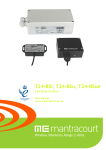
T24-BSi, T24-BSu, T24-BSue
T24 Base Station
User Manual
mantracourt.com
Introduction / Overview ........................................................................................................2
Addressing ....................................................................................................................... 2
Connections .......................................................................................................................2
T24-BSu & T24-BSue ........................................................................................................... 2
T24-BSi ........................................................................................................................... 2
SW1 Settings .................................................................................................................. 3
Address ..................................................................................................................... 3
Serial/USB .................................................................................................................. 3
Power .......................................................................................................................... 4
LED Indication ................................................................................................................ 4
RS232 .......................................................................................................................... 4
RS485 .......................................................................................................................... 4
Serial Limitations ......................................................................................................... 4
USB ............................................................................................................................. 4
Communications ..................................................................................................................5
T24 Toolkit ...................................................................................................................... 6
General Pages ................................................................................................................ 6
Setup Base Station Communications ..................................................................................... 6
Home .......................................................................................................................... 7
Analyser ....................................................................................................................... 8
Data Provider Monitor ...................................................................................................... 9
Information ................................................................................................................. 10
Save and Restore .......................................................................................................... 11
Channel and Encryption .................................................................................................. 12
Advanced Settings ......................................................................................................... 13
Advanced Multipoint Base Stations ........................................................................................ 14
Installation ....................................................................................................................... 15
Overview ....................................................................................................................... 15
Antenna Orientation ...................................................................................................... 15
Specifications ................................................................................................................... 16
General Radio ................................................................................................................. 16
T24-BSi ...................................................................................................................... 16
T24-BSu ...................................................................................................................... 16
T24-BSue .................................................................................................................... 16
Approvals ........................................................................................................................ 17
CE ............................................................................................................................... 17
FCC.............................................................................................................................. 17
Industry Canada .............................................................................................................. 18
OEM / Reseller Marking and Documentation Requirements .......................................................... 18
FCC.............................................................................................................................. 18
IC ................................................................................................................................ 18
CE ............................................................................................................................... 18
Declaration Of Conformity ................................................................................................... 20
Worldwide Regional Approvals .............................................................................................. 21
Important Note ............................................................................................................ 21
Warranty ......................................................................................................................... 21
1
Mantracourt Electronics Limited T24-BS Base Station User Manual
Introduction / Overview
Base stations are the interface between the T24 radio system and a PC, PLC or other controller.
A base station would be required to configure T24 modules from a PC using the T24 Toolkit software and also
required if you are to capture data from devices to a PC or PLC.
Addressing
Usually only a single base station is required in a telemetry installation. If a telemetry device is outside the
range of the base station a repeater may be deployed.
Some complex topologies may only be realized by using multiple base stations which may require changes to
the Address switches. (See Advanced Multipoint Base Station Section)
Our industrial base station (T24-BSi) has interfaces for USB, RS232 and RS485 and is addressable. Our USB only
base station (T24-BSu & T24-BSue) has a fixed address of 1 so only one can be connected to a PC at a time.
Connections
T24-BSu & T24-BSue
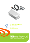
This base station simply connects to the USB port of a PC and is powered from the USB bus. The T24-BSue is an
IP65 sealed unit with increased radio range over the T24-BSu.
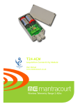
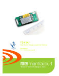
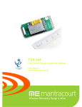
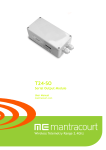
T24-BSi
This diagram shows the available connections, switches and LEDs.
ON
1
8
The interface can be selected from the DIP switches SW1 as can baudrates for serial interfaces and the Address
of the base station.
Mantracourt Electronics Limited T24-BS Base Station User Manual
2
SW1 Settings
Address
Switch positions 1 to 4 select the base station Address. This should normally be 1.
Address
1
2
3
4
5
6
7
8
9
10
11
12
13
14
15
16
1
2
3
4
Off
On
Off
On
Off
On
Off
On
Off
On
Off
On
Off
On
Off
On
Off
Off
On
On
Off
Off
On
On
Off
Off
On
On
Off
Off
On
On
Off
Off
Off
Off
On
On
On
On
Off
Off
Off
Off
On
On
On
On
Off
Off
Off
Off
Off
Off
Off
Off
On
On
On
On
On
On
On
On
Serial/USB
Switch positions 5 to 7 set whether serial or USB is used. If USB is not selected then the chosen switch settings
control the baudrate for the serial interface. Whether the serial interface is RS485 or RS232 is selected by
switch position 8.
Baudrate
USB
9600
19200
38400
57600
115200
230400
460800
5
/ USB
Off
On
Off
On
Off
On
Off
On
6
7
Off
Off
On
On
Off
Off
On
On
Off
Off
Off
Off
On
On
On
On
NOTE:
A baudrate of 9600 (and in some cases 19200) is not suitable for 2 way communication with remote devices as it is too slow and causes
timeouts. This baudrate has been included to enable the base station to be connected to a 9600 baud device to allow low rate Data
Provider packets to be received.
At any rate below 230400 is may be possible to lose packets at high data rates as the serial connection cannot keep pace with the
radio transmissions.
If USB is not selected as the interface (Switch positions 5 to 7) then this switch position selects whether the
serial interface is RS232 or RS485.
232/485
RS232
RS485
3
8
Off
On
Mantracourt Electronics Limited T24-BS Base Station User Manual
Power
If the base station is configured as USB then it will be powered by the USB bus. If RS232 or RS485 are selected
then external power will need to be connected to J4 on the –V and +V pins.
LED Indication
Two LEDS indicate Power/Mode and Activity.
The red LED indicates mode and should flash at a 2Hz rate. If any errors are detected with the radio then the
LED will remain lit.
The green LED flashes once for each packet received or transmitted via radio, USB or serial.
RS232
The RS232 interface uses TX, RX and GND to connect to a PC, PLC etc and uses standard RS232 voltage levels.
The baudrate can be selected by setting the DIP switches stated above. NOTE: the base station will require
power cycling to utilise a baudrate change.
Example connection to a PC 9 way D serial connector.
PC 9 Way D Plug Pin
3 (TX)
2 (RX)
5 (Gnd)
8 (CTS)
Signal
Direction
->
<<-
Base Station Connection
RX
TX
GND
CTS
J6 RX or J7 Pin 3
J6 TX or J7 Pin 2
J6 GND or J7 Pin 5
J6 CTS or J7 Pin 8
RS485
The RS485 interface (This is a 2 wire 485 interface and will not work with 4 wire 485 buses) uses TX, RX and
GND to connect to a PC, PLC etc and uses standard RS485 voltage levels.
The baudrate can be selected by setting the DIP switches stated above. NOTE: the base station will require
power cycling to utilise a baudrate change.
Example connection
Depending on the RS485 interface or hardware the connections vary and are not standard therefore we can only
show the connections to the base station. You must refer to the user manual regarding your RS485 connection
to ascertain the correct connections.
PC / PLC Connection
Signal
Direction
Refer to RS485 Device User Manual
Refer to RS485 Device User Manual
Refer to RS485 Device User Manual
Base Station Connection
A
B
GND
J4 -A
J4 +B
J4 SH
NOTE: There are two connectors for RS485, J4 and J5. This is to facilitate easy daisy chaining of devices if
required.
Serial Limitations
•
•
•
When using RS232 or RS485 you should use the fastest baudrate possible. At lower rates data can be
lost because it can arrive from the radio faster than the base station can send it serially.
At 9600 baud you will experience communications problems when configuring devices. This baudrate is
too slow for anything other than monitoring data provider packets from devices and even then these
should be at a low rate (around 20 per second ). The slow baudrates are provided to get low rate data
into older systems.
RS485 is a bus master system and is not ideally suited to full communications with devices when
multiple devices are providing data. This is fine for the normal operation of data acquisition but it is
recommended that only the device to be configured is active during configuration.
USB
Connection to the base station will be either a captive USB cable (T24-BSu & T24-BSue) or a USB socket B for
connection using a standard USB A-B cable (T24-BSi). There is an optional cable assembly for the T24-BSi to
provide for a USB connection while the device is still fitted to the ABS case.
Mantracourt Electronics Limited T24-BS Base Station User Manual
4
To communicate with the base station the connected device must use the USB HID Device Class and support
USB 2.0 full speed interface (12mbits).
The USB connection will also power the base station.
Communications
In a lot of installations the base station is used to configure and calibrate the T24 modules by use of the T24
Toolkit software.
In this case the user needs only connect the base station to the PC by means of a suitable interface as
described above. The Toolkit software can then be configured to use the desired interface to the base station.
If you intend to write your own software to connect to a T24 module please refer to the T24 Technical Manual
for descriptions of communications protocols.
5
Mantracourt Electronics Limited T24-BS Base Station User Manual
T24 Toolkit
The T24 Toolkit provides a means of simple configuration and calibration of the T24 modules along with useful
tools to aid integration.
Install and run the T24 Toolkit software application.
General Pages
Setup Base Station Communications
Select the required interface type and base station address.
If you are using a T24-BSu you just need to choose USB as the interface and select 1 as the Base Station
Address.
In the toolkit all items that can be changed by the user are coloured orange.
To change a value just click on the relevant orange item. You will then be presented with a new dialog window
allowing you to change the value.
This may use a slider, text box or list to allow your new value to be entered.
Click the Home button to attempt communications with the base station.
If no communications can be established the toolkit will remain on this page. You will need to check that the
base station is powered and that it is connected to the converter correctly.
Mantracourt Electronics Limited T24-BS Base Station User Manual
6
Home
We now have successful communications with the base station so we can now pair with other T24 modules or
we can select the Spectrum Analyser mode or Data Provider Monitor mode.
To connect to other T24 modules (anything other than a base station) you will need to pair to that module.
Refer to the module manual for instructions.
In this manual we are going to show how to configure the base station itself.
Please note that in normal use when connecting to other T24 modules the base station is automatically
configured to match the settings of the paired module so it is not normally required that you configure the
base station itself.
But, if for some reason you do need to (such as reducing the output power) you can ‘pair’ to the base station
by holding down the SHIFT key and clicking the Pair button.
7
Mantracourt Electronics Limited T24-BS Base Station User Manual
Analyser
The analyser page is provided as a tool and will not normally be needed unless you plan to change channels and
want to find the best channel to select, or to diagnose poor communications issues.
This page shows the radio signal levels detected across all the channels available to the T24 series of devices.
Using this tool may help in detecting noisy areas and allow you to decide on which channels you may want to
use.
The above charts show the traffic from a Wi-Fi network and it can be seen to be operating over channels 6 to 9
and it would be best (though not essential) to avoid using these channels.
Mantracourt Electronics Limited T24-BS Base Station User Manual
8
Data Provider Monitor
T24 acquisition devices normally operate in low power mode and periodically transmit Data Provider
packets
This page shows all detected Data Provider packets which may be useful for checking that a device is
operational.
NOTE: When the toolkit connects to a device to enable configuration it will usually inhibit the transmission of Data Provider packets.
The Start Logging button will ask for a filename and proceed to log the received data to a CSV file in the
following format:
Data Tag, Elasped mS, Value, Time & Date
The View Last Log button will launch the application associated with CSV files and open the last logged file.
9
Mantracourt Electronics Limited T24-BS Base Station User Manual
Information
Once successfully paired to the base station this page is displayed.
This page shows you information about the connected module.
Items you can change:
Name
You can enter a short description which may help you recognise this device in the future.
Mantracourt Electronics Limited T24-BS Base Station User Manual
10
Save and Restore
Here you can save the device settings to a file on your PC so that they can be later loaded back into the same
or different module.
Items you can change:
Save
Restore
11
Click this button to open a file dialog window to allow you to select a filename
and location to save the configuration file to.
All configuration information including calibration data will be saved to the
file.
The file extension is tcf.
Click this button to open a file dialog window to allow you to select a filename
and location of a previously saved file to load into the connected device.
All configuration information including calibration data will be overwritten.
The file extension is tcf.
Mantracourt Electronics Limited T24-BS Base Station User Manual
Channel and Encryption
Here you can change the channel and encryption key for the base station.
This is only useful if you intend to communicate with the T24 modules using your own software as in normal
operation when you ‘Pair’ to a module to configure it the base station is automatically configured to match the
radio settings of that module.
NOTE: Early acquisition modules do not yet utilise the encryption keys so these should be left at all zeros.
Items you can change:
Channel
Encryption Key
Select a channel between 1 and 16. The default is channel 1. You can use the
Spectrum Analyser mode to determine a good clean channel to use.
NOTE: Channel 16 is used to negotiate pairing so avoid this channel if possible.
Only devices with identical encryption keys can communicate. You can isolate
groups of devices on the same channel or just use the key to ensure the data
cannot be read by somebody else.
Mantracourt Electronics Limited T24-BS Base Station User Manual
12
Advanced Settings
You should not normally need to change these settings.
Items you can change:
Waker Duration
13
When you send a wake command to a T24 module via the base station the
duration of this wake attempt is controlled by this setting.
Enter the desired duration in seconds.
Mantracourt Electronics Limited T24-BS Base Station User Manual
Advanced Multipoint Base Stations
Sometimes more than one base station is required in a system. This may simply be a central PC with two base
stations wired off in opposite directions.
Where one base station handles devices on the left and the other those on the right.
Multiple base stations allow flexibility in routing requests from a PC as each time a packet is sent to a base
station it is targeted to a particular base station Address. When a packet arrives back at a PC it contains the
Address of the base station that routed it.
If a base station is the only one connected to a particular serial port then every base station can have Address
1 as the PC will send packets to a particular port to select which base station handles a packet, likewise
packets arriving back at the PC will be identified by the port that they arrive on.
RS232 devices can only be connected one at time anyway but RS485 allows multiple devices on the same bus.
This is where the Addressing is vital as it is this that distinguishes between base stations.
When using USB base stations you may only ever have one T24-BSu connected to a PC at any time. Using T24BSi will allow multiple USB base stations to be connected to single PC. Unique Addresses are again required in
this instance.
Note that broadcast packets can be received by multiple base stations so packets may appear duplicated at the
PC end.
It is also possible for the PC to route a packet through all connected base stations by Addressing a packet to
Address 0.
NOTE: Although it is possible to connect multiple USB base stations to a PC the T24drv.dll driver supplied by
Mantracourt only supports up to three Base Stations Addressed as 1 to 3.
So when using a T24-BSi which supports USB but also has a DIP switch to allow Address setting the Address
must be set between 1 and 3. The T24-BSu devices are manufactured with a fixed Address of 1.
Mantracourt Electronics Limited T24-BS Base Station User Manual
14
Installation
Overview
Radio performance at microwave wavelengths is very dependent upon the operating environment; any
structure within the operating region of the radios will give rise to three effects:
Obscuration. Obscuration will result in reduced range and occurs when an obstruction masks the line-of-sight
between radios.
Aberrations to the horizontal and vertical space patterns. Distortion of these patterns may occur if
structures or objects are placed in the near or intermediate field of the antenna. The effect will be to distort
the coverage patterns, adversely affecting range and link quality.
Reflection. Any object placed in line-of-sight of the transmit antenna will result in signals arriving at the
receiver by an indirect path. Degradation of performance due to reflection (multipath effects) appears as
reduced range or poor link quality.
Any of the above will cause poor RSSI figures, an increase in the packet loss rate and in extreme cases
complete loss of signal. Fortunately, if consideration is given to these effects at the integration stage then a
good quality link will be obtained.
Guidelines for product design:
When selecting materials for product enclosures, preference should be given to fibreglass, light coloured ABS or
Polypropylene; at the wavelength of 2.4GHz radio other materials will adversely affect the signal by
attenuation, refraction or change in polarisation.
If the application demands that the radio is fitted inside a metal enclosure then ensure that the specified
clearances are maintained around the antenna and design in a fibreglass RF window at least as large as the
clearance dimensions but ideally as large as possible.
RAD24i radios fitted inside a product should be oriented so that the chip antenna will be vertical when the
product is in its normal operating position.
Guidelines for installation:
When planning installations ensure that line-of –sight between nodes is maintained and that objects or
structures are kept at least one metre away from antennae wherever possible.
To avoid poor link quality between a RAD24i radio and a handheld device ensure that the RAD24i is mounted so
that the chip antenna is vertical. Improvement may also be obtained by altering the height above ground of the
RAD24i; a small increase or reduction in antenna elevation will often improve reception.
Range underwater is only a decimetre or so depending on packet rate. Best performance underwater is
obtained by using low packet rates and immersing water-proofed antennae rather than water-tight enclosures
containing the antennae.
Antenna Orientation
The base T24-BSi should be mounted horizontally on a wall or ceiling so that the side face containing the PCB
antenna faces the general direction of the target devices.
The T24-BSu should also be positioned to present itself to the other radios
in a 'landscape' aspect.
15
Mantracourt Electronics Limited T24-BS Base Station User Manual
Specifications
General Radio
Min
License
Modulation method
Radio type
Data rate
Radio Frequency
Power
Channels (DSSS)
T24-BSi
Parameter
External Supply voltage Range
Average Operational Current
Operating Temperature Range
Storage Temperature Range
Reverse polarity Protection
Environmental Protection
Radio Range
T24-BSu
Parameter
USB Supply Range
USB Bus Powered Operational
Current
Operating Temperature Range
Storage Temperature Range
Environmental Protection
Radio Range
T24-BSue
Parameter
USB Supply Range
USB Bus Powered Operational
Current
Operating Temperature Range
Storage Temperature Range
Environmental Protection
Typical
License Exempt
MS (QPSK)
Transceiver (2 way)
250
2.4000
Max
Units
2.4835
K bits/sec
GHz
mw
1
16
Minimum
9
-40
-40
Typical
12
100
-
Maximum
32
85
85
-32
IP65
200 (650)
Units
Maximum
5.125
Units
Notes
V DC
mA
Deg C
Deg C
V DC
Maximum Supply
Metres(feet)
See * note
Minimum
4.875
Typical
5
-
100
-
mA
-40
-40
-
85
85
IP50
100 (325)
Deg C
Deg C
Metres (feet)
Minimum
4.875
Typical
5
-
100
-
mA
-40
-40
-
85
85
IP65
Deg C
Deg C
200 (650)
Metres (feet)
Radio Range
Maximum
5.125
Volts
Units
V DC
At 12 V
Notes
As defined by
USB 2.0
Specification
See * note
Notes
As defined by
USB 2.0
Specification
Does not apply to
USB connector at
cable end.
See * note
* Maximum range achieved in open field site at a height of 3 metres above ground.
Mantracourt Electronics Limited T24-BS Base Station User Manual
16
Approvals
CE
Complies with EMC directive. 2004/108/EC
The Radio Equipment and Telecommunications Terminal Equipment (R&TTE) Directive,
1999/5/EC,
European Community, Switzerland, Norway, Iceland, and Liechtenstein
English:
This equipment is in compliance with the essential requirements and other
relevant provisions of Directive 1999/5/EC.
Deutsch:
Dieses Gerät entspricht den grundlegenden Anforderungen und den weiteren
entsprecheneden Vorgaben der Richtlinie 1999/5/EU.
Dansk:
Dette udstyr er i overensstemmelse med de væsentlige krav og andre relevante
bestemmelser i Directiv 1999/5/EF.
Español:
Este equipo cumple con los requisitos esenciales asi como con otras
disposiciones de la Directive 1999/5/EC.
Français:
Cet appareil est conforme aux exigencies essentialles et aux autres dispositions
pertinantes de la Directive 1999/5/EC.
Íslenska:
Þessi búnaður samrýmist lögboðnum kröfum og öðrum ákvæðum tilskipunar
1999/5/ESB.
Italiano:
Questo apparato é conforme ai requisiti essenziali ed agli altri principi sanciti
dalla Direttiva 1999/5/EC.
Nederlands: Deze apparatuur voldoet aan de belangrijkste eisen en andere voorzieningen
van richtlijn 1999/5/EC.
Norsk:
Dette utstyret er i samsvar med de grunnleggende krav og andre relevante
bestemmelser i EU-directiv 1999/5/EC.
Português:
Este equipamento satisfaz os requisitos essenciais e outras provisões da
Directiva 1999/5/EC.
Suomalainen: Tämä laite täyttää direktiivin 1999/5/EY oleelliset vaatimukset ja on siinä
asetettujen muidenkin ehtojen mukainen.
Svenska:
Denna utrustning är i överensstämmelse med de väsentliga kraven och andra
relevanta bestämmelser i Direktiv 1999/5/EC.
This equipment is in compliance with the essential requirements and other relevant provisions of Directive
1999/5/EC.
FCC
Family: RAD24
Models: i and e for internal and external antenna variants. For antenna T24-ANTA and T24-ANTB
FCC ID:VHARAD24
This device complies with Part 15c of the FCC Rules. Operation is subject to the following two conditions: (1) this
device may not cause harmful interference, and (2) this device must accept any interference received, including
interference that may cause undesired operation.
CAUTION: If the device is changed or modified without permission from Mantracourt Electronics Ltd, the user
may void his or her authority to operate the equipment.
17
Mantracourt Electronics Limited T24-BS Base Station User Manual
Industry Canada
Models: i and e for internal and external antenna variants. For antenna T24-ANTA and T24-ANTB
IC:7224A-RAD24
This apparatus complies with RSS-210 - Low-power Licence-exempt Radiocommunication Devices (All Frequency
Bands): Category I Equipment RSS.
OEM / Reseller Marking and Documentation Requirements
FCC
The Original Equipment Manufacturer (OEM) must ensure that FCC labelling requirements are met. This
includes a clearly visible label on the outside of the final product enclosure that displays the contents as
shown:
Contains FCC ID:VHARAD24
This device complies with Part 15 of the FCC Rules. Operation is subject to the following two conditions:
(1) this device may not cause harmful interference and
(2) this device must accept any interference received, including interference that may cause undesired operation.
The acquisition modules have been tested with T24-ANTA and T24-ANTB. When integrated in OEM products,
fixed antennas require installation preventing end-users from replacing them with non-approved antennas.
Antennas other than T24-ANTA and T24-ANTB must be tested to comply with FCC Section 15.203 (unique
antenna connectors) and Section 15.247 (emissions).
Acquisition modules have been certified by the FCC for use with other products without any further
certification (as per FCC section 2.1091). Changes or modifications not expressly approved by Mantracourt
could void the user’s authority to operate the equipment.
In order to fulfil the certification requirements, the OEM must comply with FCC regulations:
1. The system integrator must ensure that the text on the external label provided with this device is placed on
the outside of the final product.
2. The acquisition modules with external antennas may be used only with Approved Antennas that have been
tested by mantracourt.
IC
Labelling requirements for Industry Canada are similar to those of the FCC. A clearly visible label on the
outside of the final product enclosure must display the following text:
Contains Model RAD24 Radio (2.4 GHz), IC:7224A-RAD24
Integrator is responsible for its product to comply with RSS-210 - Low-power Licence-exempt
Radiocommunication Devices (All Frequency Bands): Category I Equipment RSS.
CE
The T24 series has been certified for several European countries.
If the acquisition module is incorporated into a product, the manufacturer must ensure compliance of the final
product to the European harmonized EMC and low-voltage/safety standards. A Declaration of Conformity must
be issued for each of these standards and kept on file as described in Annex II of the R&TTE Directive.
Furthermore, the manufacturer must maintain a copy of the T24 device user manual documentation and ensure
the final product does not exceed the specified power ratings, antenna specifications, and/or installation
requirements as specified in the user manual. If any of these specifications are exceeded in the final product, a
submission must be made to a notified body for compliance testing to all required standards.
OEM Labelling Requirements
The ‘CE’ marking must be affixed to a visible location on the OEM product.
Mantracourt Electronics Limited T24-BS Base Station User Manual
18
The CE mark shall consist of the initials “CE” taking the following form:
If the CE marking is reduced or enlarged, the proportions given in the above graduated drawing must be
respected.
The CE marking must have a height of at least 5mm except where this is not possible on account of the
nature of the apparatus.
The CE marking must be affixed visibly, legibly, and indelibly.
19
Mantracourt Electronics Limited T24-BS Base Station User Manual
Declaration Of Conformity
We, Mantracourt Electronics Limited
The Drive
Farringdon
Exeter
Devon EX5 2JB
declare under our sole responsibility that our products in the T24 Radio Telemetry Product Range to which
this declaration relates are in conformity with the appropriate standard EN 300 328 following the provisions of
the Radio and Telecommunications Terminal Equipment Directive 1999/5/EC, FCC CFR Title 47 part 15c BS EN
61000-4-2 and BS EN 61000-4-3 following the provisions of the EMC Directive 2004/108/EC and Low Voltage
Directive 2006/95/EC.
December 2007
Brett James
Development Manager
Mantracourt Electronics Limited.
FCC ID:VHARAD24
Mantracourt Electronics Limited T24-BS Base Station User Manual
20
Worldwide Regional Approvals
Region
Europe
USA
Canada
Australia
China
Japan
Product Conforms To
CE
FCC
IC
To Be Determined
To Be Determined
To Be Determined
Important Note
Mantracourt does not list the entire set of standards that must be met for each country. Mantracourt customers
assume full responsibility for learning and meeting the required guidelines for each country in their distribution
market. For more information relating to European compliance of an OEM product incorporating the T24 range
of modules, contact Mantracourt, or refer to the following web site: www.ero.dk
Warranty
All Telemetry products from Mantracourt Electronics Ltd., ('Mantracourt') are warranted against defective
material and workmanship for a period of (1) one year from the date of dispatch.
If the 'Mantracourt' product you purchase appears to have a defect in material or workmanship or fails during
normal use within the period, please contact your Distributor, who will assist you in resolving the problem. If it
is necessary to return the product to 'Mantracourt' please include a note stating name, company, address,
phone number and a detailed description of the problem. Also, please indicate if it is a warranty repair.
The sender is responsible for shipping charges, freight insurance and proper packaging to prevent breakage in
transit.
'Mantracourt' warranty does not apply to defects resulting from action of the buyer such as mishandling,
improper interfacing, operation outside of design limits, improper repair or unauthorised modification.
No other warranties are expressed or implied. 'Mantracourt' specifically disclaims any implied warranties of
merchantability or fitness for a specific purpose. The remedies outlined above are the buyer’s only remedies.
'Mantracourt' will not be liable for direct, indirect, special, incidental or consequential damages whether based
on the contract, tort or other legal theory.
Any corrective maintenance required after the warranty period should be performed by 'Mantracourt' approved
personnel only.
In the interests of continued product development, Mantracourt Electronics Limited reserves the right to alter product specifications without prior notice.
Code No. 517-923
21
Issue 1.4
Mantracourt Electronics Limited T24-BS Base Station User Manual
11.04.14
Distribuidor
Brasil e América do Sul
C O N TA T O
Ender eço
Rua Sete de Setembro, 2671 - C entro
13560-181 - São C arlos - SP - Brasil
Telefone
+ 55 (16) 3371-0112
Metrolog Controles de Medição
Fax
+ 55 (16) 3372-7800
Inter net
www.metrolog.net
metrolog @metrolog.net
www.metrolog.net / mantracourt.com
[email protected]
tel +55 (16) 3371-0112