1
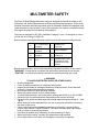
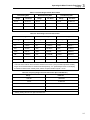
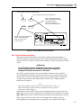
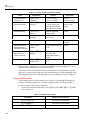
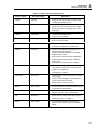
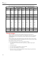
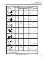
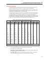
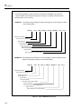
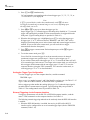
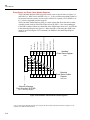
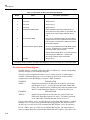
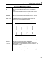
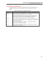
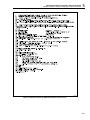
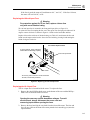
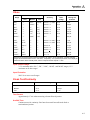
45
Users Manual
Table 3-7. Maximum Sinewave Inputs for Frequency Measurements
Range
Maximim Input Voltage
300 mV
1 V rms
3V
6 V rms
30 V
60 V rms
300 V
750 V rms
750 V
750 V rms
The input signal sensitivity is listed under the frequency specifications in Appendix A.
These values are based on sine waveforms. The signal level must be increased for lower
crest factor inputs (the crest factor is the ratio of the peak voltage to the ac rms voltage of
the waveform). If the input signal is below the required level, the frequency will be
displayed as zero. If the measurements are unstable, the input signal may be near the
threshold level.
Selecting A Function Modifier
(K, I, H, J)
Selecting a function modifier (see Figure 3-7) causes the meter to perform an action on
an input (e.g., convert to decibels or compare to another value) before a reading is
displayed. Function modifiers can be used in combination. (See “Using Function
Modifiers in Combination," later in Chapter 3.)
To use a function modifier, press a function button to select a primary function, then
press a function modifier button (or buttons). Modified readings are shown only on the
primary display.
After a function modifier has been selected, pressing any (white) function button turns off
all modifiers, causes the secondary display to go blank, and returns unmodified readings
to the primary display.
3-10