1
Appendices
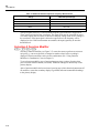
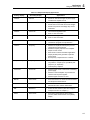
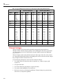
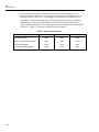
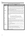
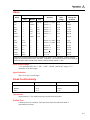
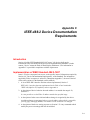
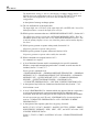
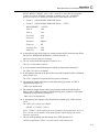
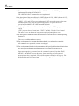
Specifications
A
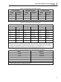
Ohms
Resolution
Range
Accuracy
Slow
Medium
Fast
Typical Full
Scale
Voltage
Max Current
Through the
Unknown
300 Ω
—
10 mΩ
100 MΩ
0.05 % + 2 + 0.02Ω
0.25
1 mA
3 kΩ
—
100 MΩ
1Ω
0.05 % + 2
0.24
120µA
30 kΩ
—
1Ω
10 Ω
0.05 % + 2
0.29
14 µA
300 kΩ
—
10 Ω
100 Ω
0.05 % + 2
0.29
1.5 µA
3 MΩ
—
100 Ω
1 kΩ
0.06 % + 2
0.3
150 µA
30 MΩ
—
1 kΩ
10 kΩ
0.25 % + 3
2.25
320 µA
300 MΩ*
—
100 kΩ
1 MΩ
2%
2.9
320 µA
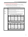
100 Ω
1 mΩ
—
—
0.05 % + 8 + 0.02 Ω
0.09
1 mA
1000 Ω
10 mΩ
—
—
0.05 % + 8 + 0.02Ω
0.10
120 µA
10 kΩ
100 mΩ
—
—
0.05 %+8
0.11
14 µA
100 kΩ
1Ω
—
—
0.05 % + 8
0.11
1.5 µA
1000 kΩ
10 Ω
—
—
0.06 % + 8
0.12
150 µA
10 MΩ
100 Ω
—
—
0.25 % + 6
1.5
150 µA
100 MΩ*
100 kΩ
—
—
2%+2
2.75
320 µA
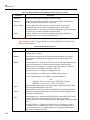
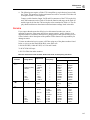
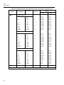
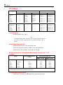
*Because of the method used to measure resistance, the 100 MΩ (slow) and 300 MΩ (medium and fast)
ranges cannot measure below 3.2 MΩ and 20 MΩ, respectively. "UL" (underload) is shown on the display for
resistances below these nominal points, and the computer interface outputs "+1 E-9".
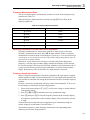
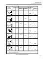
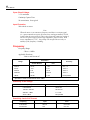
Open Circuit Voltage
3.2 V maximum on the 100 Ω, 300 Ω, 30 MΩ, 100 MΩ, and 300 MΩ ranges, 1.5 V
maximum on all other ranges.
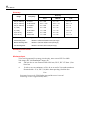
Input Protection
500 V dc or rms ac on all ranges
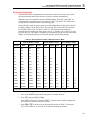
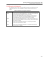
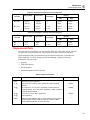
Diode Test/Continuity
Maximum Reading
Resolution
Slow
999.99 mV
10 µV
Medium
2.5 V
100 µV
Fast
2.5 V
1 mV
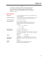
Test Current
Approximately 0.7 mA when measuring a forward biased junction.
Audible Tone
Continuous tone for continuity. Brief tone for normal forward biased diode or
semiconductor junction.
A-7