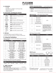
1
OPERATION MANUAL
FL5100B
Copyright © 2013
COPYRIGHT © 2012-2013 FIBERLAMP
All rights reserved. Printed in the United States of America.
This manual may not be reproduced in whole or in part, in any form or by any means, without the express written permission of
FiberLamp.
NO LIABILITY FOR ERRORS
FiberLamp reserves the right to correct technical and typographical errors in this manual at any time, without prior notice. In no
event shall FiberLamp be liable for errors in this manual or for any damages arising out of or relating to this manual.
PRODUCT WARRANTY/LIMITATION OF REMEDITS
FiberLamp warrants, to the original Buyer, all of its products to be free from defects in both workmanship and material for a
period of two year from the date of shipment. This warranty extends to all products, which have proved defective through
normal use, but excludes products that have been damaged, mishandled, disassembled without permission, modified without
written approval by FiberLamp, or misused by Buyer or any other person. This warranty is in lieu of all other warranties, and
FiberLamp disclaims all other warranties express or implied, including any warranty of merchantability, fitness for a particular
purpose, or arising from the course of dealing between the parties or usage of trade. FiberLamp does not extend any warranty
of any kind whatsoever to any purchaser of the products from Buyer or to any end-user of the products. FiberLamp, at its sole
choosing, will replace or repair to proper working condition any products under warranty that are returned. Products repaired or
replaced under warranty are only warranted for the remaining unexpired period of time of the original warranty. FiberLamp
reserves the right to issue a credit memo for any defective product as an alternative to product replacement or repair.
FiberLamp will not accept Buyer generated debit memos. Buyer may not set off or withhold payment because any product is
defective. In no event shall FiberLamp’s liability under this warranty and this contract exceed the purchase price of the
products. In no event shall FiberLamp be liable under this warranty or this contract for consequential, incidental or special
damages.
RETURN MATERIAL AUTHORIZATION TERMS
FiberLamp will only accept a return of products for which a FiberLamp Return Material Authorization (“RMA”) Number has been
issued to Buyer prior to the shipment of the return products to FiberLamp. This RMA Number must be displayed on all return
shipment documents. FiberLamp will refuse all returns that are not accompanied by an RMA Number. All risks of any such
refused shipment are the sole responsibility of Buyer.
For warranty returns, FiberLamp will only accept return products accompanied by a statement of defects. FiberLamp will not
evaluate returns not including this information, and such returns will be returned to Buyer at Buyer’s expense.
Warranty returns proved defective through damage, mishandling, disassembly without permission, modification without written
approval by FiberLamp, or misuse by Buyer or any other person, and warranty returns found non-defective, will be subject to
evaluation and processing fees, and repair costs if applicable. Non-warranty returns will be evaluated and will be subject to
evaluation and processing fees. If non-warranty repair work is necessary, Buyer will be notified of repair costs before a repair
work order is initiated. Confirming POs are required for non-warranty repair work.
For warranty returns, Buyer is responsible for one-way freight costs to FiberLamp, including any duty and taxes. FiberLamp will
cover freight costs for return shipment to Buyer. Shipment charges billed to FiberLamp without prior approval from FiberLamp
will be re-invoiced to Buyer.
For non-warranty returns, Buyer is responsible for two-way freight costs, including any duty and taxes. If shipment consists of
returns that are both warranty and non-warranty, the shipment will be considered as non-warranty.
FiberLamp will not accept Buyer generated debit memos.
All international return shipments to FiberLamp, including packaging and airway bill, must be marked “Goods made in the
United States; enter as American Goods Returned (‘AGR’)” and state the reason for the return to the United States. FiberLamp
will refuse all returns that are not properly documented. All risks of any such refused shipment are the sole responsibility of
Buyer.
International returns should be sent via Federal Express, UPS or DHL. International returns may be processed using
FiberLamp’s brokerage: EWI Inc. 305 Harbor Way, South San Francisco, CA 94080. Contact David Li at TEL: (650) 794-1388,
FAX: (650) 794-1389. If one of these carriers or FiberLamp’s broker is not used, FiberLamp may invoice Buyer for any
additional costs including duty and taxes.
REVERSE ENGINEERING/CONFIDENTIALITY
Buyer shall not reverse engineer, decompile, disassemble, modify, reproduce or copy any products or any software within any
products. Buyer shall not analyze or identify the chemical composition or the physical characteristics of any products. Buyer
shall not furnish FiberLamp specifications to any other person.
SOFTWARE LICENSE
FiberLamp does not transfer ownership of software contained in any products. FiberLamp grants to Buyer a perpetual nonexclusive license to use software in the operation of the product in which it is contained. This license is transferable only with
the transfer of ownership of the product.
FiberLamp
Copyright 2013
Terms and Conditions
ii
5870049 A2
TABLE OF CONTENTS
1.
Product Overview ................................................................4
FL5100B Overview........................................................................................................................... 4
Models.............................................................................................................................................. 4
2.
3.
Hardware Diagram ...............................................................5
Manual Operation ................................................................6
Power switch .................................................................................................................................... 6
Pushbuttons ..................................................................................................................................... 6
4.
Software Operation..............................................................8
LightMix Overview............................................................................................................................ 8
Software Installation......................................................................................................................... 8
Setup ................................................................................................................................................ 9
Definitions ........................................................................................................................................ 9
Programming to a Reserved Custom Mode..................................................................................... 9
DMX Addressing ............................................................................................................................ 13
5.
DMX Operation .................................................................. 11
DMX Overview ............................................................................................................................... 11
DMX Hardware............................................................................................................................... 11
DMX Wiring Configurations............................................................................................................ 12
DMX Controls ................................................................................................................................. 14
Master/Satellite Operation.............................................................................................................. 15
6.
Installation Recommendations........................................ 16
General........................................................................................................................................... 16
Mounting ........................................................................................................................................ 16
7.
8.
Troubleshooting................................................................ 17
Specifications.................................................................... 18
Environmental Specifications ......................................................................................................... 18
Electrical Specifications ................................................................................................................. 18
Optical Specifications.......................................................................Error! Bookmark not defined.
Mechanical Dimensions ................................................................................................................. 18
Mechanical Drawing....................................................................................................................... 19
FiberLamp
Copyright 2013
Table of Contents
iii
5870049 A1
1.
Product Overview
IMPORTANT SAFETY INFORMATION:
The FiberLamp FL5100B is a professional grade fiber optic LED luminaire. Only a licensed
professional should install this fixture.
Before installing or powering the FL5100B, read this manual and follow the safety
precautions listed below.
•
•
•
•
•
•
The FL5100B is for indoor use only, do not expose to rain or moisture.
Supply only with power that complies with local building and electrical code with
voltage between 100-240VAC at 50-60Hz.
Never bypass electrical fuse on the fixture. Replace defective fuse with fuses only of
specified type and rating.
Do not attempt to modify the fixture.
Allow a minimum 2 inches of clearance from any vent opening on the fixture.
Install away from any location likely to gather dust and debris.
FL5100B Overview
The FiberLamp FL5100B is an LED based fiber optic luminaire that has dynamic color changing
abilities and an effect wheel. It can be controlled with manual, USB, and DMX512 interfaces.
The FL5100B is designed for use with both side and end-emitting fiber optics.
Models
The FL5100B is offered with a single colored light source or a multicolored light source. All
models can be equipped with a motorized “twinkle wheel” for use with bundled strands of fiber.
COLOR OPTIONS
Multicolor options are offered as RGBW (Red, Green, Blue, 5000K White) or RGBA (Red, Green,
Blue, Amber). An FL5100B with a multicolored light source is the best option when colorchanging abilities are required.
Single color options are offered in 2800K, 3000K, 4200K, 4400K, 5000K and 6500K white color
temperatures. An FL5100B with a single colored light source is the best option when high light
intensity is required.
FIBER INSTALLATION PORT OPTIONS
The FL5100B is offered with a standard 30mm or a custom 33mm fiber installation port.
Accessories ACS30 and ACS33 are offered to couple bundles of up to 1200 fibers in the same
common end.
FiberLamp
Copyright 2013
Hardware Setup
Page 4 of 20
5870049 A2
2.
Hardware Diagram
Figure 1: Featured hardware identification diagram.
FiberLamp
Copyright 2013
Hardware Setup
Page 5 of 20
5870049 A2
3.
Manual Operation
Power switch
Once connected to the AC mains, the power switch controls the power supplied to the unit. Be
sure to set the power switch to ON before operation.
In the event of a power disconnect, when power is restored, the unit will return to its operating
state.
Note: Once the power switch is set to ON, the cooling fan should immediately operate. If the fan
fails to turn on with the power switch, but the unit is still able to output light, set the power switch
to OFF and contact the manufacturer.
Pushbuttons
There are two pushbuttons on the side of the unit labeled “Wheel Speed” and “Mode” shown in
Figure 1.
WHEEL SPEED
If a twinkle wheel is installed in the fixture, the “Wheel Speed” pushbutton is used to control the
twinkle wheel. Pressing this pushbutton cycles through different preset twinkle speed modes with
rotation in one direction (Note: Both forward and reverse rotation can be controlled with DMX).
Each mode corresponds to different twinkle speeds as described in the Table 1 below.
Table 1: Preset twinkle speed modes that can be selected using the “Wheel Speed” pushbutton
Mode
0
1
2
3
4
5
FiberLamp
Copyright 2013
Wheel Speed
Off
Slow
Slow-med
Medium
Med-fast
Fast
Manual Operation
Page 6 of 20
5870049 A2
MODE
The “Mode” pushbutton is used to select through preset lighting modes saved on the fixture.
Each mode is either a static color or a Playlist. A static color mode can only display one solid
color. A Playlist mode can display a timed sequence of color scenes. Modes 1-7 can only be
programmed as static colors. Modes 8-11 can be programmed as static colors or Playlists.
Table 2 lists the factory-preprogrammed settings for each model of FL5100B. All modes, except
for mode 0, can be reprogrammed using the LightMix software described in section 4 of this
manual.
Table 2: Factory preset modes
Mode
0
1
2
3
4
5
6
7
8
9
10
11
Programming
Capability
Non-programmable
Static Color
Static Color
Static Color
Static Color
Static Color
Static Color
Static Color
Playlist
Playlist
Playlist
Playlist
Multicolor
RGBW
RGBA
No light
No light
White
Blue
Red
Red
Green
Amber
Blue
Green
Yellow
Orange
Cyan
Chartreuse
Mixed 5000K White Mixed 5000K White
Rainbow Playlist
Rainbow Playlist
Blank
Blank
Blank
Blank
Blank
Blank
Single Color
No light
100% Intensity
90% Intensity
80% Intensity
70% Intensity
60% Intensity
50% Intensity
40% Intensity
Blank
Blank
Blank
Blank
Note: The Rainbow Playlist slowly fades between colors, while mixing to display all colors on the color pallet.
FiberLamp
Copyright 2013
Manual Operation
Page 7 of 20
5870049 A2
4.
Software Operation
LightMix Overview
The LightMix Software is designed to give users the ability to create and run any lighting scene or
sequence of lighting scenes on the FL5100B as a stand-alone fixture. LightMix also provides a
way to synchronize lighting scenes between several FL5100B fixtures in an installation.
Software Installation
LightMix is compatible with 32-bit and 64-bit systems running Windows XP, Windows Vista and
Windows 7. It is not compatible with any Mac OS.
Before installing LightMix, be sure to completely uninstall any existing versions of LightMix from
your computer.
To install, insert the CD that accompanies the FL5100B into the CD drive. Open the contents of
the CD and click on the Setup file. A window with the Setup Wizard will appear with instructions.
Follow the instructions until installation is complete.
1
2
3
4
Figure 2: Installation screenshots (left to right, top to bottom).
FiberLamp
Copyright 2013
Software Operation
Page 8 of 19
5870049 A2
Hardware Setup
1.
Make sure that the Power Switch is in the OFF position.
2.
Connect the FL5100B to the computer with a USB to Mini-USB cable.
3.
Connect the FL5100B to AC mains power.
4.
Set the Power Switch to the ON position.
5.
Open the program on the computer.
Definitions
•
Preset mode: A static color or Playlist saved on the built-in flash memory of the FL5100B.
Accessible through the pushbutton.
•
Playlist: A collection of steps built in LightMix programmed onto the FL5100B to be played
repeatedly as a dynamic color light show.
•
Profile: A small collection of steps to help construct a large and complicated Playlist,
especially useful when repetition appears frequently in the desired Playlist.
•
Step: The set of attributes (color, fade option, blink rate, time duration) that define
individual elements in a Profile or Playlist. This is also referred to as a Scene amongst
lighting designers.
•
Blink rate: Represents how fast the current step will blink. A blink rate of zero means the
step does not blink. Blink rates become increasingly faster as the blink rate is increased.
•
Fade: An option that specifies whether the color of the current step gradually fades into the
color of the next step.
•
DMX mode: Determines a fixtures role in a DMX network (Master or Slave).
•
DMX Master: If the fixture is in DMX master mode, the FL5100B will continuously send out
DMX commands to fixtures set to the same DMX address as the master. The commands
will tell DMX slave fixtures to execute the same tasks as what the DMX master executes.
When in DMX master mode, the fixture will not follow DMX commands.
•
DMX Slave: If the fixture is in DMX slave mode, the FL5100B will receive DMX commands.
If the commands are for addresses identical to those set on the fixture, the fixture will
execute according to the commands. The DMX commands can come from a DMX
controller, or a fixture in DMX master mode.
Programming a Static color Preset Pushbutton Mode
Follow the steps below to create a unique sequence of lighting scenes and save it to a preset
Playlist Mode of a fixture for stand-alone operation.
1.
2.
3.
4.
FiberLamp
Copyright 2013
Use scroll bars in the Color section to customize the color of the light output during the
step. The scroll bars control the intensity of the single color strings of LEDs in the fixture.
Select the static color mode (1-7) in the Preset Mode section tab to which the new custom
color will be saved.
Click the Write button
Disconnect the fixture from the computer and use the Mode pushbutton to select the mode
to which the new static color has been written.
Software Operation
Page 9 of 19
5870049 A2
Programming a Playlist Preset Pushbutton Mode
Follow the steps below to create a unique sequence of lighting scenes and save it to a preset
Playlist Mode of a fixture for stand-alone operation.
1.
2.
3.
4.
5.
6.
7.
8.
9.
10.
11.
FiberLamp
Copyright 2013
Use scroll bars in the Color section to customize the color of the light output during the
step. The scroll bars control the intensity of the single color strings of LEDs in the fixture.
Decide how long the step will last by choosing a Play Time in the Step Duration section
tab.
If fading throughout the step to the next step is desired, check the Fade box at the bottom
of the Step Duration section tab.
If blinking is desired throughout the step, set desired the blinking rate using the Blink Rate
scroll bar.
Once the step is complete, click Add Step at the bottom of the Step Duration section tab
and the step will be shown in detail in the Step Parameters section as a step.
Repeat until the series of steps reflect the desired lighting sequence.
Click the Save button on the right hand side of the Step Parameters section. After naming
the ‘Profile’, it will be displayed in the Saved Profiles section.
To write the ‘Profile’ to the FL5100B, Click and Drag the saved ‘Profile’ from the Saved
Profile section to the Selected Profile section.
In the section Write Selected Profile to FiberLamp at the bottom of the LightMix window,
select which ‘Playlist Number’ to assign the newly created ‘Profile’ by clicking on the empty
circle to the left of the ‘Playlist Number’. Playlist 1 will corresponds to Pushbutton mode 7,
Playlist 2 correspond to Pushbutton mode 8, etc.
Click the Write button on the right hand side of the Write Selected Profile to FiberLamp
section.
Disconnect the fixture from the computer and use the Mode pushbutton to select the mode
to which the new Playlist has been written.
Software Operation
Page 10 of 19
5870049 A2
5.
DMX Operation
DMX Overview
DMX is an abbreviation for “digital multiplex”. It is an RS-485 based protocol that has become the
industry standard for digital lighting control interfaces. DMX allows users to synchronize lighting
effects between fixtures with a centralized lighting controller.
DMX Hardware
The FL5100B is equipped with two RJ45 female connectors, an XLR5 female connector and an
XLR5 male connector. These connectors are provided such that they can be placed in a DMX
daisy chain with DMX input and output ports. If at the end of a daisy chain, a 120-Ohm
termination resistor should be applied to the DMX output port of the FL5100B.
XLR CABLE
In entertainment lighting, XLR cable is the standard for daisy chaining because its robust
construction is better suited for modular and temporary installations. This cabling can be coupled
with XLR5 connectors, which have also become standardized by the entertainment lighting
industry. The female XLR5 connector is typically used to accept a DMX data signal and the male
XLR5 connector passes a DMX signal. The male XLR5 connector is used as the DMX output
port whether in series with a daisy chain while acting in DMX slave mode, or acting in DMX
master mode.
CAT-5E CABLE
Most architectural installations use Cat-5e cable to transmit DMX data to fixtures. This cabling
can be coupled with RJ45 connectors to be compatible with the one of the RJ45 connectors on
the FL5100B. In order to daisy chain, a second Cat-5e cable with RJ45 connector can be
connected to the second RJ45 connector on the FL5100B.
PINOUTS
Table 3: Pinout assignments for RJ45 and XLR5 connectors on the FL5100B
FiberLamp
Copyright 2013
Function
XLR5
RJ45
Color
Data (+) in
3
1
White/Orange
Data (-) in
2
2
Orange
Not Assigned
5
3
White/Green
Internal use only
-
4
Blue
Internal use only
-
5
White/Blue
Not assigned
4
6
Green
DMX Ground
1
7
White/Brown
DMX Ground
1
8
Brown
Installation Recommendations
Page 11 of 19
5870049 A2
DMX Wiring Configurations
Depending on the size of the installation, there are several configurations that will ensure that
each fixture receives a clear signal.
INSTALLATIONS WITH LESS THAN 32 FIXTURES
For installations under 32 fixtures and installations less than 1,200 meters (3,900 feet) in cable
length, the signal can be daisy chained in series from one unit to the next using either Cat-5e
cable or XLR cables.
LARGER INSTALLATIONS OR LONG DISTANCE
Installations requiring more than 32 fixtures or installations spanning cable lengths greater than
1,200 meters (3,900 feet) will need to use a DMX amplifier. Due to the limitations of the RS-485
protocol, this is needed to ensure that each string of 32 fixtures receives sufficient signal strength.
DATA TERMINATION
It is always recommended to terminate DMX daisy chains with a resistor of the same
characteristic impedance as the cable (typically 100-120 Ohms). To terminate a DMX daisy
chain, place the resistor across Data pin (+) and Data pin (-), which are specified in Table 3.
FiberLamp
Copyright 2013
Installation Recommendations
Page 12 of 19
5870049 A2
DMX Addressing
The FL5100B is controlled with 8 DMX channels and must be assigned to 8 DMX addresses.
The DIP-switch on the side of the FL5100B defines the first DMX address of the sequence of 8
DMX addresses. The 7 remaining addresses are automatically assigned to the 7 addresses that
succeed the address set on the DIP-switch. (For example, if the DIP-switch is set to address #4,
the FL5100B will be controlled by DMX channels 4, 5, 6, 7, 8, 9, 10 and 11.)
Table 4 can be used as a guide for configuring the DIP-switch to any DMX address. To
determine the DIP-switch configuration that corresponds to a DMX address, find the DMX
address in the table below. Then set the DIP-switch such that pins 1-5 are set as described on
the left hand side of the table and pins 6-9 are set as described at the top of the table, with
respect to the specific DMX address.
Table 4: DIP-switch setting table for assigning an FL5100B to a specified DMX address
#9
0
0
0
0
0
0
0
0
1
1
DIP-switch Settings
#8
0
0
0
0
1
1
1
1
0
0
0 = OFF
#7
0
0
1
1
0
0
1
1
0
0
1 = ON
#6
0
1
0
1
0
1
0
1
0
1
#1 #2 #3 #4 #5
0
0
0
0
0
32
64
96 128 160 192 224 256 288
1
0
0
0
0
1
33
65
97 129 161 193 225 257 289
0
1
0
0
0
2
34
66
98 130 162 194 226 258 290
1
1
0
0
0
3
35
67
99 131 163 195 227 259 291
0
0
1
0
0
4
36
68 100 132 164 196 228 260 292
1
0
1
0
0
5
37
69 101 133 165 197 229 261 293
0
1
1
0
0
6
38
70 102 134 166 198 230 262 294
1
1
1
0
0
7
39
71 103 135 167 199 231 263 295
0
0
0
1
0
8
40
72 104 136 168 200 232 264 296
1
0
0
1
0
9
41
73 105 137 169 201 233 265 297
0
1
0
1
0
10
42
74 106 138 170 202 234 266 298
1
1
0
1
0
11
43
75 107 139 171 203 235 267 299
0
0
1
1
0
12
44
76 108 140 172 204 236 268 300
1
0
1
1
0
13
45
77 109 141 173 205 237 269 301
0
1
1
1
0
14
46
78 110 142 174 206 238 270 302
1
1
1
1
0
15
47
79 111 143 175 207 239 271 303
0
0
0
0
1
16
48
80 112 144 176 208 240 272 304
1
0
0
0
1
17
49
81 113 145 177 209 241 273 305
0
1
0
0
1
18
50
82 114 146 178 210 242 274 306
1
1
0
0
1
19
51
83 115 147 179 211 243 275 307
0
0
1
0
1
20
52
84 116 148 180 212 244 276 308
1
0
1
0
1
21
53
85 117 149 181 213 245 277 309
0
1
1
0
1
22
54
86 118 150 182 214 246 278 310
1
1
1
0
1
23
55
87 119 151 183 215 247 279 311
0
0
0
1
1
24
56
88 120 152 184 216 248 280 312
1
0
0
1
1
25
57
89 121 153 185 217 249 281 313
0
1
0
1
1
26
58
90 122 154 186 218 250 282 314
1
1
0
1
1
27
59
91 123 155 187 219 251 283 315
0
0
1
1
1
28
60
92 124 156 188 220 252 284 316
1
0
1
1
1
29
61
93 125 157 189 221 253 285 317
0
1
1
1
1
30
62
94 126 158 190 222 254 286 318
1
1
1
1
1
31
63
95 127 159 191 223 255 287 319
FiberLamp
Copyright 2013
Installation Recommendations
1
0
1
0
1
0
1
1
1
1
0
0
1
1
0
1
1
1
1
0
1
1
1
1
320
321
322
323
324
325
326
327
328
329
330
331
332
333
334
335
336
337
338
339
340
341
342
343
344
345
346
347
348
349
350
351
352
353
354
355
356
357
358
359
360
361
362
363
364
365
366
367
368
369
370
371
372
373
374
375
376
377
378
379
380
381
382
383
384
385
386
387
388
389
390
391
392
393
394
395
396
397
398
399
400
401
402
403
404
405
406
407
408
409
410
411
412
413
414
415
416
417
418
419
420
421
422
423
424
425
426
427
428
429
430
431
432
433
434
435
436
437
438
439
440
441
442
443
444
445
446
447
448
449
450
451
452
453
454
455
456
457
458
459
460
461
462
463
464
465
466
467
468
469
470
471
472
473
474
475
476
477
478
479
480
481
482
483
484
485
486
487
488
489
490
491
492
493
494
495
496
497
498
499
500
501
502
503
504
505
506
507
508
509
510
511
Page 13 of 19
5870049 A2
DMX Controls
The FL5100B is controlled with 8 DMX channels as shown in Table 5 below. These channels can
be assigned, in series only, to any of the 512 addresses within the DMX universe.
Table 5: DMX channel sequence table for different models.
DMX
Channel
Sequence
1
2
3
4
5
6
7
8
Single
Color
White Light
White Light
White Light
White Light
Mode 7
Model
Multicolor
RGBW
RGBA
5000K White Light
Blue Light
Red Light
Red Light
Green Light
Amber Light
Blue Light
Green Light
Mode 7: Mixed 5000K White
Mode 7: Mixed 5000K White
Master Intensity
Twinkle Wheel
Strobe
LIGHT OUTPUT CONTROL
Channels 1-6, in the sequence of 8 shown in Table 5, are channels that control the light output of
the FL5100B. As DMX controls operate on an incremental number scale from values of 0 to 255,
a DMX value of 0 corresponds to no light and a DMX value of 255 corresponds to maximum light
output.
Channels 1-4 correspond to individual colors on the LED light source. In multicolor models, new
colors can be achieved with varying intensity combinations.
Channel 5 controls the intensity of a color combination created in the LightMix software and
saved to Mode 7. For multicolor models, Mode 7 is calibrated at the manufacturing facility to the
brightest 5000K White light possible from the light source.
Channel 6 is the master intensity control (If channel 6 is set to DMX value 0, then no light
will turn on, even with channels 1-5 set to max intensity). Having a Master intensity channel
gives the advantage of finding a color using channels 1-4 and controlling its intensity without
changing that color.
TWINKLE WHEEL CONTROL
The twinkle wheel control operates on the same incremental number scale from values of 0 to
255 as all other DMX controls. DMX channel 7 of the FL5100B controls both the rotational speed
and direction of the twinkle wheel.
The values in this channel are split. The lower half of the number values, 1 to 127, correspond to
twinkle wheel speeds in one rotational direction, and the higher half of the number values, 129 to
255, correspond to twinkle wheel speeds in the opposite rotational direction. The values 0 and
128 are reserved to stop the twinkle wheel from rotating as shown in Table 4 below.
Table 6: Twinkle wheel response to DMX signals
DMX
Value
Wheel
Response
FiberLamp
Copyright 2013
0-1
1 - 127
126 - 131
132 - 255
Stop
Slow → Fast
Stop
Fast → Slow in opposite direction
Installation Recommendations
Page 14 of 19
5870049 A2
STROBE CONTROL
DMX channel 8 controls the strobe rate of the light. A DMX value of 0 on this channel will not
strobe the light. A DMX value of 255 on this channel will strobe the light settings on channels 1-6
very fast.
Master/Slave Operation
The FL5100B is able to act as a DMX Slave or a Master on the DMX line, depending on the
settings declared using the software. Each FL5100B is preprogrammed to DMX Slave mode as a
factory default setting.
DMX MASTER OPERATION
When in DMX Master mode, the FL5100B broadcasts the display color, twinkle wheel speed and
strobe rate as a DMX signal at the configured DMX addresses on the fixture from the DMX ports
described in the DMX Hardware section above. Note: When in DMX Master mode, the FL5100B
cannot not receive incoming DMX signals.
To engage DMX Master Mode, follow these instructions:
1.
Connect the FL5100B to a PC with the USB cable and launch the LightMix software.
2.
On the designated master FL5100B fixture, verify that the DMX base address is the same
as all of the Slave units in the installation. If not, set the respective DMX address on the
fixtures DIP-switch.
3.
In the DMX mode section to the bottom left of LightMix window, check the “Master” bubble
and click “Set.”
4.
After the FL5100B has been properly installed at the desired physical location, turn on the
unit. Use the push button to access the desired preprogrammed mode, and then plug in the
DMX data cable that connects it to the Slave units.
DMX SLAVE OPERATION
When in DMX Slave mode, the FL5100B receives DMX signals from a DMX controller, and will
respond if the DMX addresses it is configured to matches that of the DMX controller. Note: The
DMX controller may be either a third party device or the FL5100B configured in DMX Master
mode.
To ensure that the FL5100B responds properly to DMX signals, make sure the unit is configured
to be in DMX Slave mode and set to the correct DMX addresses.
To engage DMX Slave Mode, follow these instructions:
1.
Connect the FL5100B to the PC with the USB cable and launch the LightMix software.
2.
On the FL5100B fixture, verify that the DMX base address corresponds to the respective
addresses on the DMX controller. If not, set the respective DMX address on the fixtures
DIP-switch
3.
In the DMX mode section to the bottom left of LightMix window, check the “Slave” bubble
and click “Set.”
After the FL5100B has been properly installed at the desired physical location, turn the unit
on, and plug in the data cable from the DMX controller. Verify that the DMX controller is
outputting signal and that the FL5100B is responding accordingly.
4.
FiberLamp
Copyright 2013
Installation Recommendations
Page 15 of 19
5870049 A2
6.
Installation Recommendations
General
The FL5100B is intended for indoor use only. Installation should take into consideration room for
access to all input and output ports, as well as easy access to manual controls.
COOLING FAN OBSTRUCTION
The cooling fan is an important factor in prolonging the lifetime of the LED light source. It is
important that the input and output vents are clear of any obstructions so that there is proper
airflow though the device for cooling.
Install the FL5100B in a location free from dust and debris, as the fan will pull in any dust and
debris within a close proximity. Excessive dust and debris build up within and around the
FL5100B will decrease the performance of the thermal management system, resulting in a
shortened lifetime of the LED light source.
Mounting
The FL5100B uses dynamic thermal management and can therefore be mounted in any
orientation seen fit by the installer.
SURFACES
The mounting plate at the bottom of the unit is fit to be mounted on wood, masonry, drywall, or
metal. Use the four 5mm holes on the four corners of the base to mount to a surface with
recommended M4 screws. Be sure that the mounting surface is capable of supporting the weight
of the unit.
HANGING APPARATUS
There are two 11mm holes at the center of the front and back ends of the mounting plate. These
holes are meant to secure two rigging clamps to the unit using recommended M10 bolts and lock
nuts. Verify that the clamps and mounting structure can safely support the weight of the unit
along with anything else relying on the structure for support.
FiberLamp
Copyright 2013
Installation Recommendations
Page 16 of 19
5870049 A2
7.
Troubleshooting
Table 5: Possible problems and remedies for FL5100 failure.
Problem
Remedy
Make sure that the power switch is set to ON.
Unit does not turn on
Hit the push button several times to make sure that the unit is not in the “off” mode or a
blank mode.
Use LightMix and check for individual light channel response. If responsive, click the
“Restore” button to restore the preset modes to the external pushbuttons.
Light output only
appears red
Fan does not turn on
Unit is not emitting all
of the colors
Make sure that the protective dust cover on the end cap has been removed.
Push the button several times to engage different color modes.
The fan should be on constantly while the power switch is set to ON. If the fan fails to
engage, turn off the unit immediately and contact the manufacturer.
Hit the push button several times and scroll through the factory preset modes. If any of
the colors appear unusually dim, check each scroll bar in LightMix for full intensity
control. If still dimmer than usual, please contact the manufacturer.
Use LightMix to check for individual color channel response. If responsive, click the
“Restore” button to restore the preset modes to the external pushbuttons. If any of the
channels are not completely responsive, please contact the manufacturer.
Verify that the addresses set on the DIP-switch correspond to the channels being
controlled on the DMX controller.
If there is no light, make sure that the 6th channel in the address sequence is set to a
DMX value >0.
Unit is not responding
to DMX signal
Make sure the fixture is not set to DMX Master mode.
Make sure the pin assignments and polarities on the DMX connectors are properly
aligned.
Terminate the DMX signal line with a resistor of the same characteristic impedance as
the cable.
Check to verify that the DMX controller is broadcasting a signal by connecting it to a
different fixture.
Check to make sure that the twinkle wheel is stopped.
If occurring on a Playlist mode, write another Playlist to the flickering Playlist mode and
check if flickering still occurs. If flickering persists, contact manufacturer.
Unit flickering issue
If occurring on a static factory preset mode, contact manufacturer.
If connected to DMX, make sure the strobe channel is set to a DMX value of 0.
If warm and the fan is not operating correctly, turn off and contact manufacturer.
There is no light output
and the unit is no
longer cool to the touch
FiberLamp
Copyright 2013
Check to make sure the fan is operating properly and the device is being used within its
environmental temperature range defined in the Specifications section.
Make sure there is nothing obstructing the airflow to the FiberLamp.
Troubleshooting
Page 17 of 19
5870049 A2
8.
Specifications
Environmental Specifications
Table 6: Environmental Specifications for the FL5100B
Operating Temp. Range
Storage Temperature Range
Humidity
0/40°C
-40/+70°C
10-90%
Electrical Specifications
Table 7: Electrical Specifications for the FL5100B
Input Voltage Range
Input Frequency Range
Power Rating
100-240V AC
50-60Hz
100W
Mechanical Dimensions
Table 9: Mechanical Dimensions
FiberLamp
Copyright 2013
Parameter
Dimension
Base
289mm x 135mm
Height
110mm
Specifications
Page 18 of 19
5870049 A2
Mechanical Drawing
All measurements are in mm.
FiberLamp
Copyright 2013
Specifications
Page 19 of 19
5870049 A2