1
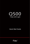
OPERATION MANUAL Indoor/Outdoor Models FL210 FL211 FL2100 FL2110 UL/cUL Listed Copyright © 2013 COPYRIGHT © 2012-2013 FiberLamp All rights reserved. Printed in the United States of America. This manual may not be reproduced in whole or in part, in any form or by any means, without the express written permission of FiberLamp. NO LIABILITY FOR ERRORS FiberLamp reserves the right to correct technical and typographical errors in this manual at any time, without prior notice. In no event shall FiberLamp be liable for errors in this manual or for any damages arising out of or relating to this manual. PRODUCT WARRANTY/LIMITATION OF REMEDITS FiberLamp warrants, to the original Buyer, all of its products to be free from defects in both workmanship and material for a period of one year from the date of shipment. This warranty extends to all products, which have proved defective through normal use, but excludes products that have been damaged, mishandled, disassembled, modified, or misused by Buyer or any other person. This warranty is in lieu of all other warranties, and FiberLamp disclaims all other warranties express or implied, including any warranty of merchantability, fitness for a particular purpose, or arising from the course of dealing between the parties or usage of trade. FiberLamp does not extend any warranty of any kind whatsoever to any purchaser of the products from Buyer or to any end-user of the products. FiberLamp, at its sole choosing, will replace or repair to proper working condition any products under warranty that are returned. Products repaired or replaced under warranty are only warranted for the remaining unexpired period of time of the original warranty. FiberLamp reserves the right to issue a credit memo for any defective product as an alternative to product replacement or repair. FiberLamp will not accept Buyer generated debit memos. Buyer may not set off or withhold payment because any product is defective. In no event shall FiberLamp’s liability under this warranty and this contract exceed the purchase price of the products. In no event shall FiberLamp be liable under this warranty or this contract for consequential, incidental or special damages. RETURN MATERIAL AUTHORIZATION TERMS FiberLamp will only accept a return of products for which a FiberLamp Return Material Authorization (“RMA”) Number has been issued to Buyer prior to the shipment of the return products to FiberLamp. This RMA Number must be displayed on all return shipment documents. FiberLamp will refuse all returns that are not accompanied by an RMA Number. All risks of any such refused shipment are the sole responsibility of Buyer. For warranty returns, FiberLamp will only accept return products accompanied by a statement of defects. FiberLamp will not evaluate returns not including this information, and such returns will be returned to Buyer at Buyer’s expense. Warranty returns proved defective through damage, mishandling, disassembly, modification, or misuse by Buyer or any other person, and warranty returns found non-defective, will be subject to evaluation and processing fees, and repair costs if applicable. Non-warranty returns will be evaluated and will be subject to evaluation and processing fees. If non-warranty repair work is necessary, Buyer will be notified of repair costs before a repair work order is initiated. Confirming POs are required for non-warranty repair work. For warranty returns, Buyer is responsible for one-way freight costs to FiberLamp, including any duty and taxes. FiberLamp will cover freight costs for return shipment to Buyer. Shipment charges billed to FiberLamp without prior approval from FiberLamp will be re-invoiced to Buyer. For non-warranty returns, Buyer is responsible for two-way freight costs, including any duty and taxes. If shipment consists of returns that are both warranty and non-warranty, the shipment will be considered as non-warranty. FiberLamp will not accept Buyer generated debit memos. All international return shipments to FiberLamp, including packaging and airway bill, must be marked “Goods made in the United States; enter as American Goods Returned (‘AGR’)” and state the reason for the return to the United States. FiberLamp will refuse all returns that are not properly documented. All risks of any such refused shipment are the sole responsibility of Buyer. International returns should be sent via Federal Express, UPS or DHL. International returns may be processed using FiberLamp’s brokerage: EWI Inc. 305 Harbor Way, South San Francisco, CA 94080. Contact David Li at TEL: (650) 794-1388, FAX: (650) 7941389. If one of these carriers or FiberLamp’s broker is not used, FiberLamp may invoice Buyer for any additional costs including duty and taxes. REVERSE ENGINEERING/CONFIDENTIALITY Buyer shall not reverse engineer, decompile, disassemble, modify, reproduce or copy any products or any software within any products. Buyer shall not analyze or identify the chemical composition or the physical characteristics of any products. Buyer shall not furnish FiberLamp specifications to any other person. SOFTWARE LICENSE FiberLamp does not transfer ownership of software contained in any products. FiberLamp grants to Buyer a perpetual non-exclusive license to use software in the operation of the product in which it is contained. This license is transferable only with the transfer of ownership of the product. FiberLamp Copyright 2013 Terms and Conditions Page 1 of 24 5870004A3 TABLE OF CONTENTS 1) PRODUCT OVERVIEW ............................................................................................................................ 3 FiberLamp Overview................................................................................................................................. 3 Models ...................................................................................................................................................... 3 2) HARDWARE SETUP ............................................................................................................................... 4 FL210/FL211 Configuration ...................................................................................................................... 4 FL2100/FL2110 Configuration .................................................................................................................. 5 3) MANUAL OPERATION ............................................................................................................................ 6 Push Button .............................................................................................................................................. 6 Off Mode ................................................................................................................................................... 6 Single Color Modes .................................................................................................................................. 6 Rainbow Mode .......................................................................................................................................... 6 Playlist Modes........................................................................................................................................... 6 Return to Mode ......................................................................................................................................... 6 4) SOFTWARE OPERATION ....................................................................................................................... 7 LightMix Overview .................................................................................................................................... 7 Installation................................................................................................................................................. 7 Getting Started.......................................................................................................................................... 8 LightMix Definitions................................................................................................................................... 8 Navigating the LightMix Software ............................................................................................................. 8 Light Control.............................................................................................................................................. 9 Writing a Custom Static Color to the FiberLamp ...................................................................................... 9 Creating a Playlist ..................................................................................................................................... 9 Writing a Playlist to the FiberLamp......................................................................................................... 10 Setting the DMX Address ....................................................................................................................... 10 Setting the DMX Mode............................................................................................................................ 10 5) DMX OPERATION ................................................................................................................................. 11 DMX Overview ........................................................................................................................................ 11 DMX Hardware ....................................................................................................................................... 11 DMX Wiring Configurations .................................................................................................................... 12 Master/Slave Operation .......................................................................................................................... 14 6) INSTALLATION RECOMMENDATIONS ............................................................................................... 15 General ................................................................................................................................................... 15 Mounting ................................................................................................................................................. 16 Outdoor Installation................................................................................................................................. 17 Enclosures .............................................................................................................................................. 17 7) TROUBLESHOOTING ........................................................................................................................... 18 8) SPECIFICATIONS .................................................................................................................................. 19 Environmental Specifications.................................................................................................................. 19 Absolute Maximum Ratings .................................................................................................................... 19 Optical Performance .................................................................................Error! Bookmark not defined. Mechanical Dimensions .......................................................................................................................... 19 Mechanical Drawings.............................................................................................................................. 20 FiberLamp Copyright 2013 Table of Contents Page 2 of 24 5870004A3 1 PRODUCT OVERVIEW The FiberLamp is a professional grade fiber optic LED illuminator. Only a licensed professional should install this fixture. FiberLamp Overview FiberLamps are LED based fiber optic illuminators that have tunable white and dynamic color changing capabilities with manual, USB, and DMX512 interfaces. FiberLamps come in actively or passively cooled models, the advantages of each are dependent on the application and environment. The FiberLamp line is designed for use with side-emitting and end-emitting fiber optics. Sideemitting fiber optics extracts light along the length of the fiber to provide the look of neon, but do not have any electrically active parts and are flexible. End-emitting fiber optics transport light from one end of the fiber to the other with minimal loss to create many point sources using a single illuminator. side-emitting fiber end-emitting fiber Models This manual is intended for use with the following FiberLamp models: FL210 FL211 FL2100 FL2110 The FL210 and FL2100 are UL approved for damp locations. The FL211 and FL2110 are UL approved for wet locations. Please reference the product label to confirm that you are using one of these models. If not, contact the manufacturer or visit www.fiberlamp.com for the proper user manual. FiberLamp Copyright 2013 Product Overview Page 3 of 24 5870004A3 2 HARDWARE SETUP FL210/FL211 Configuration The FL210 and FL211 have the driver electronics built into the illuminator. The unit requires a 12V DC power supply with at least a 3A current capacity. Figure 1: Wiring configuration for FL210 and FL211. (Left to right) DC power supply, illuminator, and fiber. FL210/FL211 CONTROLS Figure 2: (Left to right) DMX RJ45 connector, USB connector, DC power receptacle, and push button. FiberLamp Copyright 2013 Hardware Setup Page 4 of 24 5870004A3 FL2100/FL2110 Configuration The FL 2100 and FL2110 have the driver electronics built into the illuminator. The unit requires a 12V DC power supply with at least a 3 A current capacity. Figure 3: Wiring configuration for FL2100 and FL2110. (Left to right) DC power supply, illuminator, and fiber. FL2100 CONTROLS Figure 4: (Left to right) Push button, DC power receptacle, USB connector, and RJ45 connector. FL2110 CONTROLS Figure 5: (Left to right) DC power receptacle, push button, protective cover for the USB connector (must be removed for programming), and RJ45 connector. FiberLamp Copyright 2013 Hardware Setup Page 5 of 24 5870004A3 3 MANUAL OPERATION Push Button A push button is located at the rear of the unit to manually operate the FiberLamp. This button is used to scroll through all the modes on the FiberLamp. Table 1: Preprogrammed Modes Mode Color 0 OFF 1 Red 2 Green 3 Blue 4 Cyan 5 Yellow Mode 6 7 8 9 10 11 Color Magenta White Rainbow Custom Note: Modes 8-11 are customizable Playlist modes. Off Mode The lamp is “off” in mode zero. This mode cannot be reprogrammed. Single Color Modes There are seven single color modes on the FiberLamp. These modes store static colors (no color changing or fading) on the device. Default single colors are red, green, blue, cyan, yellow, magenta, and white for modes 1-7, respectively. To use any of the single color modes, press the push button until you find the proper mode. The colors on the first seven preset modes can be reprogrammed using LightMix (See section 4 for details). Rainbow Mode The FiberLamp also has a slow color cycling program, called the “Rainbow Mode”, set to mode 8 by default. To use the “Rainbow Mode”, press the push button until you reach mode 8. This mode can be reprogrammed as a custom Playlist in LightMix (See section 4 for details). Playlist Modes Modes 8-11 are four reserved as custom Playlist modes in the FiberLamp flash memory. Each mode is capable of storing dynamic lighting effects on it, which can be created and saved to the FiberLamp using LightMix (see section 4 of this manual). Modes 9-11 are by default empty as the FiberLamp leaves the factory and will not show any light until programmed. Modes 8-11 correspond to Playlist Numbers 1-4 in the LightMix Software, respectively. (See section 4 for details) Return to Mode The FiberLamp has a Return to Mode feature that allows it to return to the same mode it was on originally in the event of a power failure. FiberLamp Copyright 2013 Manual Operation Page 6 of 24 5870004A3 4 SOFTWARE OPERATION LightMix Overview The LightMix Software is designed to enable users with creating their own custom colors and playlists and saving them onto the FiberLamp. LightMix is also used to assign DMX512 addresses to the individual color control features of each FiberLamp. Installation LightMix can be installed on PCs running Windows XP, Windows Vista and Windows 7. LightMix is not compatible with Macintosh operating systems. To install, insert the CD that accompanies the FiberLamp into the CD drive. Open the CD drive and click on the Setup file. A window with the Setup Wizard will appear with instructions. Follow the instructions until installation is complete. 1 2 3 4 Figure 6: Installation screenshots (left to right, top to bottom). FiberLamp Copyright 2013 Software Operation Page 7 of 24 5870004A3 Getting Started 1. Connect the FiberLamp to the PC using the provided USB to mini-USB cable. 2. Connect the power cord to the FiberLamp. 3. Launch the LightMix Software. LightMix Definitions • Preset Mode: A static color saved on the built-in flash memory of the FiberLamp. Preset Modes are accessible using the push button. • Playlist: A sequence of Profiles to be saved on and executed by the FiberLamp that is looped as a continuous dynamic light show. • Profile: A sequence of Steps grouped to ease the construction of a Playlist. Profiles are especially useful when repetition appears frequently in a Playlist, analogous to a chorus in a song. • Step: A single executable, defined by a set of attributes (color, duration, fade, blink rate), which can be listed in a Profile or Playlist. • Channel: The FiberLamp uses the Dense Matrix LED as a light source. The Dense Matrix TM LED is a single platform populated with many high-powered LEDs on different circuits. The TM FiberLamp uses a 4 circuit Dense Matrix LED and populates LEDs of the same color within the same circuit. Each circuit will be distinguished by different colored LEDs within it and are called the FiberLamp channels. • Blink rate: Represents how fast the current step blinks. A blink rate of zero means the step does not blink. Blink rates become increasingly faster as the blink rate is increased. • Fade: An option that specifies whether the color of the current step gradually fades into the color of the next step in a Scene or Playlist. The alternative is that the step’s color remains constant throughout its duration. The TM Navigating the LightMix Software • Banner: Located at the top of the software window. Scrolls back to show information for troubleshooting purposes. • “Refresh” Button: Located in the top, right-hand corner of the software window. This button is used to reestablish the communication link between the LightMix software and the FiberLamp. • “Color” Section: Located in the upper, left-hand side of the software window. This section contains several scroll bars that control the intensity of different colored LED channels in the FiberLamp. There are also options to synchronize the channel control such that each scroll bar is increased or decreased together, and an option to view the intensity of each channel as index or percentage. • “Step Duration” Tab: Located in the lower, left-hand side of the software window. This tab is used when you want to build a Profile. This tab is used to set the duration, the blink rate and the fading effect of a Step within a Profile. • “Preset Mode” Tab: Located behind the Step Duration tab. This tab is used to read or write a static color set to a Preset Mode the FiberLamp. It can also be used to restore modes 1-6 back to factory settings. Each Preset corresponds to a pushbutton setting for when the FiberLamp is to be operated while disconnected from a controller. • “DMX Address” Tab: Located in the bottom, left-hand corner of the software window. This tab is used to set the DMX addresses of the designated control features of the FiberLamp. (See section 5 for a full description of these features) FiberLamp Copyright 2013 Software Operation Page 8 of 24 5870004A3 • “DMX Mode” Tab: Located behind the DMX Address Tab. This tab is used to set the FiberLamp into a DMX Master or DMX Slave mode. This tab can also be used to query the FiberLamp for its DMX mode status. • “Step Parameters” Section: Located in the upper, right-hand side of the software window. This section shows the list of Steps created that is intended to be saved as a Profile. The list of Steps in this section available for editing. • “Saved Profile” Section: Locate in the lower, middle region of the GUI window. section shows the list of all of the Profiles that have been created on the PC in use. • “Selected Profile” Section: Located in the lower, right-hand side of the GUI window. This section lists all of the Profiles to be saved as a Playlist on a FiberLamp. • “Write Selected Profile to FiberLamp” Section: Located in the bottom, right-hand side of the GUI window. This section is used to write the Playlist shown in the Selected Profile section to a designated pushbutton mode on a FiberLamp. This Light Control To control the light from the FiberLamp in real-time, use the scroll bars in the “Color” section of LightMix. Scrolling from left to right will increase the intensity of the light. When controlling a color-changing model, such as the Mixed RGB or Tunable White model FiberLamp, changing the intensity ratios between channels can change the color of the light. Writing a Custom Static Color to the FiberLamp 1. In the “Color” section, change the intensity ratio between channels until you achieve the target custom static color. 2. Select the “Preset Mode” tab. 3. Select the mode number to which the custom static color will be saved. 4. Click on the “Write” button. 5. Click “Yes” to confirm that you want to overwrite the Preset Mode. 6. Use the pushbutton to verify that the custom static color has been saved in the correct mode position. Creating a Playlist 1. In the “Color” section, create the color of the a the first Step of a Profile. 2. In the “Step Duration” tab, set the Play Time of the step to the duration of the first Step. 3. If blinking is desired for the first Step, use the Blink Rate scroll bar to set the blink frequency of the light during the Step. 4. If fading from the color of the first Step to the color of the second Step is desired, check the Fade box. 5. If the Color, Play Time, Blink Rate and Fade are correct, click the “Add Step” button. The Step and its attributes should appear in the “Step Parameters” section. 6. Repeat 1-5 above until a Profile is completed. If any Steps need editing, click on the Step to be edited in the “Step Parameters” section, create the correct step attributes for the selected Step in the “Color” section and “Set Duration” tab, then click the “Update” button. You may also preview the sequence of Steps in the “Step Parameters” section on the FiberLamp by clicking the “Preview” button in the right-hand side of the “Step Parameters” section. 7. If all Steps listed in the “Step Parameters” section are correct, click the “Save” button on the right-hand side of the “Step Parameters” section. FiberLamp Copyright 2013 DMX Operation Page 9 of 214 5870004A3 8. When the “Save Current Scene” pop-up window appears, create a name for the Profile being saved, type it in the designated box, and click “OK”. The Profile name will then appear in the “Saved Profile” section with the extension .fsc. 9. Repeat 1-8 above until all of the desired Profiles are created, saved and can be found as a .fsc file in the in the “Saved Profile” section. 10. In the order in which the Playlist will play the selected Profiles, click and drag Profiles from the “Saved Profiles” section to the “Selected Profiles” section. The Profile names will appear in the “Selected Profiles” in the order in which they were dragged over. If any Profiles were dragged over to the “Selected Profiles” section out of order, select the Profile and click the “Remove” button, then proceed with dragging Profiles to the “Selected Profiles” section in the correct order. 11. If the Profile sequence is correct, it can be saved as a Playlist to any location on the PC by clicking the “Save” button on the right-hand side of the “Selected Profiles” section. 12. Select the appropriate location on the PC to save the Playlist, name it and save. The Playlist will be saved with the extension .fpl, can be loaded to the “Selected Profiles” section anytime in the future by clicking the “Load” button. Writing a Playlist to the FiberLamp 1. Fill the “Selected Profiles” section with the desired sequence of Profiles by dragging Profiles in order from the “Saved Profiles” section, or load an existing Playlist by clicking the “Load” button and selecting the desired Playlist. To preview the Playlist before it is written to the FiberLamp, click the “Preview” button. 2. With the correct Playlist loaded to the “Selected Profiles” section, in the “Write Selected Profile to FiberLamp” section, select the Playlist Number to which the Playlist will be written. (Note: Playlist Numbers 1-4 correspond to pushbutton modes 8-11, respectively) 3. Click the “Write” button on the right-hand side of the “Write Selected Profile to FiberLamp” section. 4. When the “Write to FiberLamp” pop-up window appears, click “Yes”. 5. Use the pushbutton to verify that the Playlist has been saved in the correct mode position. Setting the DMX Address 1. In the “DMX Address” tab, select the Base Address number that corresponds to the first of the reserved DMX addresses for the FiberLamp in a DMX512 network. (See section 6 for FiberLamp DMX address control features) 2. Click the “Set” button. 3. When the “Set DMX Address” pop-up window appears, click “Yes”. Setting the DMX Mode 1. In the “DMX Mode” tab, select Master if the FiberLamp is to act as a DMX Master, or Slave if the FiberLamp is to act as a DMX Slave. (See section 6 for DMX Master/Slave definitions) 2. Click the “Set” button. 3. Click “OK” when the pop-up appears. FiberLamp Copyright 2013 DMX Operation Page 10 of 214 5870004A3 5 DMX OPERATION DMX Overview DMX is the common name for the abbreviated “digital multiplex”. It is an EIA-485 based protocol that has become the industry standard for digital lighting control interfaces. Because of the physical properties as defined by EIA-485, the DMX data signal can be passed from fixture to fixture in daisy-chain fashion, facilitating a large network of fixtures synchronized to one control signal. A DMX controller will supply a constant flow of data to the DMX network so that all units on the daisy-chain knows what it should be doing at all times. DMX Hardware The FL210 and FL2100 come with female RJ-45 connectors, and the FL211 and FL2110 come with a male RJ-45 connector. The RJ-45 connection is used for connection to a DMX network with data pinout assignments listed below. CAT-5E CABLE Most architectural installations use Cat-5e cable to transmit DMX signals to the fixtures. This cabling is usually coupled with RJ45 connectors to be compatible with the FiberLamps. In order to daisy chain, you can splice the data cable to connect the illuminators in series-parallel configuration, or use a T-line splitter (recommended). Figure 14 shows a possible configuration for daisy chaining using Cat-5e cable. Figure 7: Diagram of a FiberLamp linked to a T-line splitter for daisy chaining using Cat-5e cable. XLR CABLE In entertainment lighting, XLR cable has become the standard because of its robust construction. (This is the same type of cable used for microphones.) XLR cable is better suited for modular/temporary installations. To connect the FiberLamp using an XLR connector, an XLR to RJ-45 adapter must be fabricated, or the DiCon ACS-XLR adapter can be used. The DiCon ACSXLR adaptor (see Figure 16) has female and male XLR connection for easy daisy-chain configurations. It connects to the FiberLamp with a short Cat-5e cable. FiberLamp Copyright 2013 DMX Operation Page 11 of 214 5870004A3 XLR ADAPTOR Figure 8: Diagram of a FiberLamp linked to a DiCon XLR adapter for daisy chaining using XLR cable. PINOUTS Table 2: Pinout for RJ45 connector RJ45 Color Function XLR3 XLR5 1 White/orange Data (+) in 3 3 2 Orange Data (-) in 2 2 3 White/green Not Assigned - 5 4 Blue Internal use only - - 5 White/blue Internal use only - - 6 Green Not assigned - 4 7 White/brown DMX Ground 1 1 8 Brown DMX Ground 1 1 Figure 9: Cat-5e cable with RJ-45 connector wiring diagram. DMX Wiring Configurations Depending on the size of the installation, there are several configurations that will ensure that each illuminator is supplied with a clear data signal for synchronized installations. FiberLamp Copyright 2013 Installation Recommendations Page 12 of 21 5870004A3 INSTALLATIONS WITH LESS THAN 32 ILLUMINATORS For DMX networks in installations that include under 32 units, or for installations less than 1,200 meters (3,900 feet) in length, the signal can be daisy chained in series from one unit to the next using either Cat-5e cable or XLR cables. Figure 18 shows a typical daisy chain configuration. The end of the DMX daisy chain must be properly terminated. Figure 10: Daisy chain configuration with data termination. LARGER INSTALLATIONS OR LONG DISTANCE Installations requiring more than 32 units or installations spanning lengths greater than 1,200 meters (3,900 feet) will need to use a splitter/amplifier to ensure that each string of thirty FiberLamps receives sufficient signal strength. Figure 11: Daisy chain configuration for larger installations requiring more than thirty-two illuminators or cable length in excess of 1200 meters (3,900 feet). FiberLamp Copyright 2013 Installation Recommendations Page 13 of 21 5870004A3 DATA TERMINATION It is always recommended that daisy chains be terminated with a resistor of the same characteristic impedance as the cable (typically 100-120 Ohms will be sufficient). To terminate a daisy chain, place the resistor across RJ-45 pins 1 and 2 as shown in Figure 20. Figure 12: Wiring diagram for placing a resistor across data lines to eliminate signal reflection. Master/Slave Operation The FiberLamp is able to act as a DMX master or slave in a DMX network, depending on its DMX Mode settings. DMX MASTER OPERATION When in DMX master mode, the FiberLamp sends DMX commands to all other fixtures in the same DMX network. The commands from the FiberLamp in DMX master mode include information about what it is currently executing. Because DMX slaves only execute commands sent to them, the slaves will execute exactly what the DMX master is executing. Note: When in DMX master mode, the FiberLamp will not receive any incoming DMX commands. Follow the “DMX Mode” setting procedure in section 4 to set the FiberLamp to DMX master DMX SLAVE OPERATION When in DMX slave mode, the FiberLamp receives and executes DMX commands from a DMX network. To ensure that the FiberLamp responds properly to DMX commands, make sure the unit is configured to be in DMX slave mode and set to the correct DMX address. After the FiberLamp has been properly installed at the desired physical location, connect to power, and connect to the DMX network. Verify that the DMX controller for the network is sending the correct commands, the signal strength is adequate and that the FiberLamp is responding accordingly. FiberLamp Copyright 2013 Installation Recommendations Page 14 of 21 5870004A3 INSTALLATION RECOMMENDATIONS 6 General These recommendations apply primarily to indoor FiberLamp installations where the unit will be attached to a portable power supply and plugged into standard line voltage. POWER SUPPLY Power supplies that accompany FiberLamps are not suitable for outdoor or recessed environments. Do not install these power supply units in a location that may expose them to moisture. The FiberLamp is UL listed if installed using a power supply provided by the manufacturer. If the manufacturer does not supply the power supply, a Class 2 power supply is required for UL Listing compliance. If you are unsure of the safety rating of your power supply, please contact the manufacturer. CONNECTOR Most FiberLamps employ a standard 2.1mm x 5.5mm female DC barrel connector for simple plug-and-play operation. Do not use this device to hang the FiberLamp in any way. Other FiberLamps have wire leads only for direct DC connection. WIRE LENGTH FiberLamps should be configured to be within fifteen feet of their power supply. DC Voltage tends to drop linearly with respect to distance. Keeping the FiberLamp close to the power supply will ensure that the unit is receiving enough voltage to operate properly. USING A POWER SUPPLY WITHIN A JUNCTION BOX This diagram below shows a typical wiring configuration for using a power supply that is built within a junction box. A compression fitting should be used on each side to protect the wiring connection from dust/debris and to provide strain relief. Be sure to ground the A/C wire input securely on the enclosure. In order to wire directly to the FiberLamp, strip the wire connected to the unit and place it inside the junction box so that the strain relief is on the larger outermost wire jacket. Figure 13: Wiring using a power supply with built-in junction boxes on both sides. FiberLamp Copyright 2013 Installation Recommendations Page 15 of 21 5870004A3 USING A CUSTOM ENCLOSURE FOR THE POWER SUPPLY When using a custom enclosure, always allow enough space to make wiring connections. Use some type of strain relief fitting on each end of the enclosure. Be sure to ground the A/C wire input securely on the enclosure. In order to wire directly to the FiberLamp, strip the wire connected to the unit and place it inside the junction box so that the strain relief is on the larger outermost wire jacket. Figure 14: Wiring using a power supply in a custom enclosure ACOUSTICS Although the FiberLamps have been engineered for minimal fan noise, the acoustics of these units should not be overlooked in any installation, especially residential. If acoustic noise less than 32 dBa are required, consider a fanless unit (FL210 and FL211). Mounting The FiberLamp can be installed in many environments in various orientations. The following considerations should be made before choosing a mounting location: SURFACES The mounting plate can be mounted onto wood, masonry, drywall, or metal. Use the four holes on the base to mount to a surface. Be sure that the mounting surface is capable of supporting the weight of the fiber lamp. DUST/DEBRIS Actively cooled models (FL2100 and FL2110) circulate more air volume, but they are also more prone to pulling in dust and debris from their installation site. Avoid using these units if they are going into an environment with excessive amounts of dust or debris. ORIENTATION On passively cooled models (FL210 and FL211), if possible, orient such that the LED array module faces downward. By doing this, the natural convection is most effective and the unit will run cooler, ultimately prolonging its lifetime. DiCon Lighting Copyright 2010 Troubleshooting Page 16 of 21 5870004A2 Outdoor Installation These recommendations apply to installations where the FiberLamp will be in an outdoor environment. SOLAR LOADING FiberLamps used during the day should be installed at a location where it will be shielded from the sun. The absorption of sunlight will increase operating temperature substantially and shorten the lifetime of the device. WEATHER RATINGS The FL211 and the FL2110 are designed to withstand exposure to high-pressure water. These models are not intended for submersion. MOUNTING ORIENTATION Do not install with the endcap oriented up. If exposed to water, water can accumulate in the endcap, submersing the LED array. Enclosures If possible, avoid using an enclosure. If an enclosure is necessary for the installation, take the following precautions to make sure that the units can operate properly: VENTILATION Ensure adequate ventilation for the enclosure. The recommended ventilation allowed per fixture is 18 cfm. DRAINAGE When using an enclosure in a wet environment, it is important to create drainage. The FL211 and FL2110 are not suitable for submersion, so make sure enclosures have adequate drainage. DiCon Lighting Copyright 2010 Troubleshooting Page 17 of 21 5870004A2 7 TROUBLESHOOTING Table 3: Possible problems and remedies for FiberLamp failure Problem Remedy Lamp does not turn on Check that the green light on the power adapter is on and verify that all of the connections to the adapter and the FiberLamp are properly connected. Hit the push button several times to make sure that the unit is not in “off” mode. Light output only appears red Fan does not turn on FiberLamp is not emitting all of the colors Make sure that the protective dust cover on the end cap has been removed. Push the button several times to engage different color modes. The fan will only turn on when the unit’s temperature reaches a critical point. To verify that the fan is operating properly, hit the push button to go to the white mode. Allow the FiberLamp to run for several minutes to verify that the fan is engaging. If the fan fails to engage within 20 minutes with an ambient temperature above 20°C, turn off the unit immediately and contact the manufacturer. Hit the push button several times and scroll through the seven factory preset colors. If any of the colors appear unusually dim, please contact the manufacturer. Make sure the pin assignments and polarities on the DMX connectors are configured correctly DMX signal is not reaching the lamp Terminate the DMX signal line with a 100-120 Ohm resistor. Check to verify that the DMX controller output signal strength is sufficient. Connect the FiberLamp to LightMix and change the DMX address to a new assignment and apply DMX signal. Flickering is often a result of the driver not receiving a high enough DC voltage. Make sure that 12V±0.5V is applied to the FiberLamp. Lamp flickering issue Shorten the line from the power supply to the FiberLamp. Never exceed more than a 15 ft length from the power supply. Power cycle the FiberLamp by shutting off the power to the power supply and restarting. FiberLamp has shut down and is hot Check to make sure the fan is operating properly and the device is being used within its environmental temperature range (see Mounting in Installation Recommendations, section 6). Make sure there is nothing obstructing the airflow to the FiberLamp. DiCon Lighting Copyright 2010 Troubleshooting Page 18 of 21 5870004A2 8 SPECIFICATIONS Environmental Specifications Table 4: Environmental specifications for all FiberLamp models Model Operating Temp. Range Storage Temp. Range Humidity IP Rating FL210 -20/+45 °C (-4/113 °F) -40/+75 °C (-40/167 °F) 10-90% IP40 FL211 -20/+45 °C (-4/113 °F) -40/+75 °C (-40/167 °F) 10-90% IP66 FL2100 -20/+45 °C (-4/113 °F) -40/+75 °C (-40/167 °F) 10-90% IP40 FL2110 -20/+45 °C (-4/113 °F) -40/+75 °C (-40/167 °F) 10-90% IP56 Absolute Maximum Ratings Table 5: Absolute maximum ratings for all FiberLamp models Model Input Voltage Input Current FL2100/ FL2110/ FL210/ FL211 12 V DC (±5%) 3.0 A Mechanical Dimensions Table 7: Mechanical dimensions for all FiberLamp models Model Dimensions (Illuminator) FL210 191 (L) x 110 (W) x 111 (H) FL211 210 (L) x 110 (W) x 111 (H) FL2100 140.4 (L) x 60 (W) x 59.6 (H) FL2110 135 (L) x 75 (W) x 83.6 (H) FiberLamp Copyright 2013 Specifications Page 19 of 21 5870004A3 Mechanical Drawings FL210 FL211 FiberLamp Copyright 2013 Specifications Page 20 of 21 5870004A3 FL2100 FL2110 FiberLamp Copyright 2013 Specifications Page 21 of 21 5870004A3