Transcript
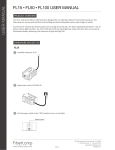
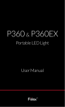
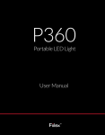
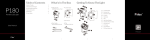
36W FiberLamp
Quick Start Manual
A. Contents
F. Connecting to DMX
• FiberLamp
• LightMix Software
1. Connect the DMX line to FiberLamp using Cat-5e cable with
• USB to mini-USB cable
• 12V DC Power Supply (optional)
2. The Cat-5e wiring configuration for the RJ45 connection to
an RJ45 connector.
DMX is as specified in the following table:
• IEC 60320 C13 to NEMA 5-15 AC Power Cable (optional)
RJ45 Pin
Cat-5e Wire
1
White/Green
Data (+)
2
Green
Data ( - )
Function
3
White/Orange
Not Assigned
DC input cable with 2.1mm x 5.5mm
4
Blue
Internal use only
5
White/Blue
Internal use only
6
Orange
Not Assigned
7
White/Brown
DMX Ground
8
Brown
DMX Ground
B. Connectors
Connectors
A
DC connector or fly-leads
B Pushbutton
C Mini-USB port for LightMix interface
D RJ45 connector for DMX control
C. Electrical Power Set-up
Connect 12V DC power supply to DC input cable on FiberLamp:
• DC connector - Use mating female 2.1mm x 5.5mm DC
barrel connector
• Fly-leads - Connect (+) polarity to white lead
- Connect ( - ) polarity to black lead
D. Using Pushbutton
1. Press Pushbutton several times until light turns on.
2. Light changing sequence is as specified in the following table:
Mode
Generic
Description
RGBW
Single Color
0
Off
Blank
Blank
1
Static Color
Red
100% Intensity
2
Static Color
Green
90% Intensity
3
Static Color
Blue
80% Intensity
4
Static Color
Cyan
70% Intensity
5
Static Color
Yellow
60% Intensity
6
Static Color
Magenta
50% Intensity
7
Static Color
6500K White
40% Intensity
8
Timed Color
Sequence
Rainbow
Default Blank
9
Timed Color
Sequence
Default Blank
Default Blank
10
Timed Color
Sequence
Default Blank
Default Blank
11
Timed Color
Sequence
Default Blank
Default Blank
G. DMX Channel Definitions
The DMX channels below represent the sequence in which the
controls appear on the DMX controller. Use LightMix to set the DMX
address of the first control in the table below. The controls that follow
in each sequence will automatically be set to corresponding DMX
addresses that follow the setting of the first control (example: for an
RGB unit, by setting red to DMX address 6, green will automatically
be set to DMX address 7, blue to 8, etc.)
Control Sequence
RGB
Single Color
1
Red
Master Intensity
2
Green
Strobe
3
Blue
NA
4
Max 6500K White
NA
5
Strobe
NA
Note: Strobe values 0-1: No Blinking; 2-255 blink rate increases
from slow (2) to fast (255).
H. Troubleshooting
Remedy
Problem
Make sure that the FiberLamp is connected to a
constant 12V DC source that can provide at least 3A.
LightMix does
not work
If LightMix was previously installed, uninstall all
versions of LightMix and reinstall the latest version.
Click on the refresh button in the right corner of the
LightMix window.
Use LightMix to reset the desired DMX channels.
E. Connecting to LightMix
1. Run LightMix installer from CD or FiberLamp.com on a computer
running Windows XP, Windows Vista or Windows 7. LightMix is
not compatible with Macintosh operating systems.
DMX does
not work
Use LightMix to reset the FiberLamp to DMX Slave mode.
Make sure that the DMX wiring configuration matches
the DMX wiring configuration of the DMX controller.
Note: Not all DMX controllers and devices use the same wiring
configuration. Make sure the wiring configuration of the FiberLamp
and the DMX controller match.
2. Use USB to mini-USB cable to connect FiberLamp to computer.
3. Open LightMix.
DMX Line
1689 Regatta Blvd, Richmond, CA 94804
http://www.fiberlamp.com
[email protected] / (510) 620-5000
5870028A1