Transcript
FL5100B
Quick Start Manual
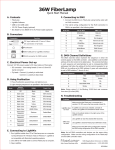
A. Contents
Examples of Dip-switch settings
• FL5100B
• IEC 60320 C13 to NEMA 5-15 AC Power Cable
• USB to Mini-USB Cable
• LightMix Software
1
2
3
4
10
*Totals
Value when
switched up
1
2
4
8
16 32 64 128 256
8
9
N
-
Example 1
U
U
D
D
U
D
U
U
D
N
211
Example 2
D
D
U
U
U
D
U
D
D
N
92
DMX Channels / DMX Channel Table for RGBW:
A IEC 60320 C14 Plug for AC Input
Channel
Definition
1
White channel
2
Red channel
C DIP-Switch for DMX Addressing
3
Green channel
4
Blue channel
D Push Buttons for Manual Control (2)
5
Max 5000K White
Mini-USB Port for Programming
Standalone Operations
6
Master light intensity
B Power Switch
E
7
N= Null
*Totals: DMX address of fixtures first control channel
Function
Connectors
6
D= Down
Dip-Switches
B. Connector and Diagram Switch
5
U= UP
F RJ45 Connectors for DMX (2)
Values
7
Twinkle Wheel
0-1: Wheel stopped; 2-125:
Wheel turns clockwise from
slow (2) to fast (125); 126-131:
Wheel Stopped; 132-255:
Wheel turns counter clockwise
from fast (132) to slow (255)
8
Strobe control
0-1: No Blinking; 2-255 blink
rate increases from slow (2) to
fast (255)
G Male XLR5 Connector for DMX
H Femal XLR5 Connector for DMX
C. Set-up
0-255
DMX Channel Table for RGBA:
1. Use Power Cable to connect FL5100B to AC mains
2. Set the power switch so that the ( ) symbol is pressed down
D. Using the Pushbutton
Press the Pushbutton to find the output setting in sequence as shown
in the table below:
Channel
Definition
Values
1
Blue channel
2
Red channel
3
Green channel
4
Amber channel
0-255
Mode
RGBW
RGBA
0
Non-programmable: Blank
Non-programmable: Blank
1
Static Color: White
Static Color: Blue
2
Static Color: Red
Static Color: Red
3
Static Color: Green
Static Color: Amber
4
Static Color: Blue
Static Color: Green
5
Static Color: Yellow
Static Color: Orange
6
Static Color: Cyan
Static Color: Chartreus
7
Static Color:
Max Intensity 5000K White
Static Color:
Max Intensity 5000K White
8
Timed Color Sequence:
Rainbow
Timed Color Sequence:
Rainbow
9
Timed Color Sequence:
Default Blank
Timed Color Sequence:
Default Blank
10
Timed Color Sequence:
Default Blank
Timed Color Sequence:
Default Blank
RJ45
XLR5
Function
Timed Color Sequence:
Default Blank
Timed Color Sequence:
Default Blank
1
3
Data (+)
2
2
Data (-)
3
5
Not Assigned
4
-
Internal Use Only
11
Press the Twinkle Wheel push button to activate the twinkle wheel
with speed in sequence as shown in the table below:
5
Max 5000K White
6
Master light intensity
7
Twinkle Wheel
0-1: Wheel stopped; 2-125:
Wheel turns clockwise from
slow (2) to fast (125); 126-131:
Wheel Stopped; 132-255:
Wheel turns counter clockwise
from fast (132) to slow (255)
8
Strobe control
0-1: No Blinking; 2-255 blink
rate increases from slow (2) to
fast (255)
DMX Pin-outs
5
The DMX data Pin-outs for the respective
connector types on the FL5100B are as follows:
1
1
4
3
female
3
4
male
Mode
1
2
3
4
5
5
-
Internal Use Only
Setting
Slow
Slow-Med
Medium
Med-Fast
Fast
6
4
Not Assigned
7
1
DMX Ground
8
1
DMX Ground
E. DMX Controls
5
2
2
DMX Addressing
The DIP-Switch settings are binary.The value of
these settings represents the DMX address of
the first of the series of eight DMX channels
shown in the following table.
1689 Regatta Blvd, Richmond, CA 94804
http://www.fiberlamp.com
[email protected] / (510) 620-5000
5870017A1