1
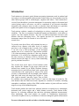
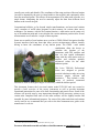
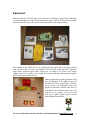
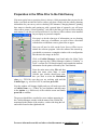
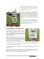
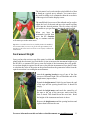
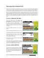
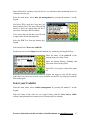
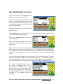
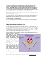
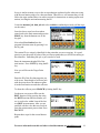
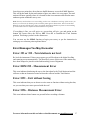
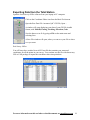
Introduction & Simple Guide to
Using the Leica Total Station
Ted MacKinnon & Jonathan Murphy
This document was originally submitted as part of
a requirement for the Applied Geomatics Research
advanced Post Graduate Diploma at COGS in 2004.
(In 2011 it was revised & updated by T. MacKinnon).
Table of Contents
TABLE OF CONTENTS ............................................................................................................................. 1
INTRODUCTION ........................................................................................................................................ 2
EQUIPMENT ............................................................................................................................................... 4
PREPARATION IN THE OFFICE PRIOR TO THE FIELD SURVEY................................................ 5
USER INTERFACE..................................................................................................................................... 8
OPERATING THE INSTRUMENT IN THE FIELD............................................................................... 9
SETUP ......................................................................................................................................................... 9
CENTERING & LEVELING THE UNIT .......................................................................................................... 10
INSTRUMENT HEIGHT ............................................................................................................................... 11
SURVEYING FROM A KNOWN POINT............................................................................................... 12
CREATE A MEASURE JOB FILE .................................................................................................................. 12
CREATE A DATA JOB FILE ........................................................................................................................ 12
SELECT YOUR CODELIST .......................................................................................................................... 13
RECORD BACKSIGHT LOCATIONS ............................................................................................................. 14
SURVEYING FROM AN UNKNOWN POINT ...................................................................................... 15
ERROR MESSAGES YOU MAY ENCOUNTER .................................................................................. 17
ERROR 353 OR 352 - TOTAL STATION IS NOT LEVEL ................................................................................. 17
ERROR EDM 255 - MEASUREMENT ERROR .............................................................................................. 17
ERROR 5391 – EXIT WITHOUT SAVING ..................................................................................................... 17
ERROR 5396 – DISTANCE MEASUREMENT ERROR .................................................................................... 17
EXPORTING DATA FROM THE TOTAL STATION ......................................................................... 18
For more information on this and other related documents see tmackinnon.com
1
Introduction
Total stations are electronic optical distance-measuring instruments used in modern land
surveying to record topographic and man made features (they are also sometimes used by
other interest groups such as archaeologists, engineers and others). Total stations have
evolved from theodolites (precision instruments for measuring angles in horizontal and
vertical planes) and in one-sense can still be considered as an electronic theodolite
integrated with a distance meter in order to calculate slope and distances to particular
points and capable of diverse mapping and spatial position measuring tasks.
Total stations combine a number of technologies to achieve remarkable accuracy and
reliability. The first, an extension of traditional transits and theodolites, is the ability to
register very fine angular divisions. The error of radial measurements increases with
distance from the measuring device. The angular precision for common theodolite
instruments ranges from 20 seconds of arc to less than 1
second of arc.
To provide some idea of how well positional accuracy is
conserved over distance with these levels of angular
precision, a rule of thumb is that 1 second of arc is about
1 cm error over a 2000 m distance, so the maximum
angular error of a 1 second of arc Total station would be
1 cm when measuring a point that is 2 km away from the
instrument. A 10 second of arc instrument would achieve
the same accuracy at a distance of 200 m. Therefore total
stations increase the range of a survey while maintaining
precise positional accuracies.
The second, more novel aspect of total stations is that
they measure the distance to the target point with an
infrared laser emitted by an EDM (electronic distance
measuring device) and reflected back with a prism held
vertically above the actual point of interest. The actual
accuracy is determined by the wavelength of the infrared
light used, and errors can range from as little as 1 mm
plus 1 ppm to around 5 mm plus 5 ppm. Thus, at 2,000
m, a distance error would vary from 3 mm to 15 mm over this range of accuracies. The
total distance that the EDM can measure depends on a number of variables, including
atmospheric conditions, quality of the EDM, and the number of prism reflectors used as
targets over top of the destination points.
Total stations produce the same basic spherical measures as optical survey instruments;
horizontal and vertical angles and a radial distance measure. Total stations differ,
however, by collecting additional data and then calculating additional measurements.
Most importantly, most total stations are capable of simultaneous trigonometric
conversion of spherical survey coordinates to Cartesian orthogonal spatial measurements
For more information on this and other related documents see tmackinnon.com
2
(usually east, north, and altitude). The coordinates of the setup position of the total station
can also be inputted by the user (or found within a data register) and consistently offset
from the measured points. This allows all measurements to be taken with reference to a
single datum, eliminating the need to manually adjust the data from different local
datums to the overall site grid.
Computational abilities go far beyond simple transformations, and most total stations
carry a number of useful other programs in their memory for various other survey
techniques. For instance, with the free station function, a total station can be setup over
top of an unknown point and it can calculate the current unknown position after several
measurements are recorded to a couple of known points.
Some newer models of total stations now even have GNSS (Global Navigation Satellite
System) interfaces built into them that allow precise measurements without virtually
having to know the coordinates of any known points. The GNSS / total station
combination allow the device to
calculate the location of the
instrument with GPS satellites and
then use that spatial information
along with the total station tools to
measure and calculate spatially
referenced values for the other
unknown points.
The Leica TPS1100 Professional
Series was designed to provide
practical solutions to make surveying
processes simple, efficient and
productive. 1 They include a wide
variety of practical, automated
functions to achieve the highest degree of efficiency within the shortest period.
This document features the Leica total station model TCR1105 and was created to
provide a brief overview of the survey instrument as well as provide important
operational instructions for some of its basic functionality and practical uses. Some of the
sections will provide step by step instructions through all the necessary actions to get
certain tasks completed and some of the other sections will be slightly broader and
intended for more informational purposes. For some of the other tasks that total stations
can be used for we recommend that you refer to the brief instrument user guide or the
manufacturer’s web site.
1
Leica TPS1100 Professional Series Marketing Brochure TPS1100_us.pdf
For more information on this and other related documents see tmackinnon.com
3
Equipment
Included with the TCR1105 unit are several pieces of hardware used in the calibration,
set up and maintenance of the Total Station device (note: various TCR1105 units or other
total station models may not have the exact items that we have shown below).
The contents in our TCR1105 case are displayed in the photo above, clockwise starting
with top left corner are; basic user manual, TCR1105 total station unit and 2 batteries,
target plate, computer serial cable, flash card, car charger, AC power cord, battery
charger, lens cover, weather cover, height meter (measuring tape and customized plastic
hook), and various allen hex keys.
Other equipment used in the operation of the
unit are displayed in the photo on the left
and include a survey grade tripod, reflective
survey prisms and aluminum poles with
height measurement labelled and built in
level bubbles to mount the prisms onto. The
reflective survey prisms can also be used
with survey grade tripods (shown below)
when mounted on tribrachs.
For more information on this and other related documents see tmackinnon.com
4
Preparation in the Office Prior to the Field Survey
Like most typical survey practises, there is always a little preparation that you need to do
before you head out into the field to collect your data. Along with the usually planning
information for your survey such as checking GPS almanacs, charging batteries, printing
base maps or sketches and coming up with a general plan of approach, you will most
often want to create a “Data Dictionary” code list for the data you wish to collect with the
total station. To do this you will need to have Leica Survey Office software suite installed
on your laptop or personal computer.
First step is to decide what type of information you are planning
to collect, what type of attributes you wish to have associated
with the data set and then create a general list on paper.
Next you will need to click on the Leica Survey Office icon to
initiate the software program. After the software has started up,
you should see a narrow rectangular window with a configuration
like shown in the image on the left.
Click on Codelist Manager icon found under the Main Tools
group to open up the Codelist Manager window (“Codelist” is
Leica’s version of a GIS data dictionary and contains the attribute
information for the points collected by the Total Station).
From the main menu select File and then
under that menu select New. A small
Codelist type window should pop open,
here you need to select the Instrument
class (e.g. TPS1100) type that you are working with and the
Codelist type (e.g. advanced GSI 16) and then press OK.
Next the window will change slightly and you will need to provide
a Codelist Name: (e.g. TSMan) for your attributes and then enter
in the Author (e.g. mackinnon) of the codelist creator and finally
press OK to continue.
The process should have resulted in a new window appearing in
the Codelist Manager window with the name of the codelist file
mentioned in the header of the window, a white side along the left
and a table found on the right hand side.
For more information on this and other related documents see tmackinnon.com
5
Click on the white portion of the Codelist window along the left hand side, and you will
notice the window will then change on the right hand side allowing you to now enter the
first entry line of your new codelist and the name of your codelist that you just created
will appear on the left hand side of the window..
Next click in the Code field and begin entering all of your codes, descriptions, short cuts
and type of data for your attributes (Note: Shortcuts only work for type equal to free, or
when a Code is not really describing an object.). Once you have all tour attributes entered
into the codelist window, chose File from the main menu and then select Save to save
your new code list.
[Note: A Total Station only collects point data. You can however generate lines or
polygon data later on while post processing the data after you return to the office]
For more information on this and other related documents see tmackinnon.com
6
To upload your new codelist to your Total Station you will need to use the Data
Exchange Manager icon found in the Main Tools section of the Leica Survey Office
window. Once you do this the Data Exchange Manager should have open up and look
similar to a file manager window. Connect the Total Station to your PC using the
provided serial cable (ensure the instrument is level, and turned off while you are
connecting it) An Alternate method is to remove the PCMCIA card and use a card reader
or you can also use an internal PC Card slot for any data transfer). After the unit is
connected to the PC it should turn itself on.
The total station files will appear in the file tree in the left hand side and your computer
files should appear in the file tree in the right hand window. Locate the codelist file
(*.crf) that you created from the directory file tree on the right hand side of the window,
then drag it over to the left hand side of the window and drop it into the folder called
CODE found on the memory card of the total station unit. A progress window should
open up and your file will begin to upload to the unit.
After the file has completed uploading, choose FILE from the main menu of the Data
Exchange Manager window and then select EXIT to close the window. Next close the
Leica Survey Office window. Finally switch off the total station instrument and
disconnect the serial cable from your computer.
For more information on this and other related documents see tmackinnon.com
7
User Interface
The key-pad on the total station is a fairly simple input tool that provides user’s the
ability to select various items in the display window using a number of different ways to
access the instruments wide range of functionalities. The display window is made up of
several items stored in menu like configuration. The header of the window allows the
user to know what menu they are choosing options for and a dark cursor bar lets the user
know what option they could select if they were using the control keys. Items on the
screen above those selections can be chosen by using either the arrow keys or by using
the function keys.
Using the function keys (e.g. F1, F2, F3 etc.) located along the bottom of the illuminated
screen allows the user to quickly make selections by choosing items from the displayed
menus based on number. The escape function allows a user to either cancel a selection
that they did not intend to make or to go back to the previous menu.
The upper left key pad is capable of typing letters as well as numbers. Each button is
capable of providing one of three different characters. To use the letters on the key pad
you must be in a field that supports letters, use the highlighted function key to switch
between numbers and letters and you press the button once for the first letter, twice
quickly for the second and three times quickly for the third one. (e.g. the 7 key can also
be used to provide the letters A, B, & C. To select an A you would tap the key once, two
hits in quick succession would provide the letter B and three hits in quick succession
would provide the letter C).
To turn the unit off, both the left and right arrow keys need to be pressed and held at the
same time.
Tip: If you become lost in the menus remember that the escape ESC key will bring you back to the previous
screen and eventually to the main menu.
Display Window
Input Keys
Header
Cursor bar
Function Key
Assignment
Function Keys
Control Keys
Escape Function
Application Programs
Additional Functions
For more information on this and other related documents see tmackinnon.com
8
Operating the Instrument in the Field
Setup
Find the location where you want to set up the survey
instrument, it can be over either a known point with
coordinates (usually a survey pin or monument) or an
unknown one (can be any type of point - If one is not
present beforehand place a surveyor’s stake with a
crosshair in the ground pushed flush into the soil)
without coordinates but it should be setup on top of
some sort of distinct feature.
Open up the survey grade tripod and extend the three
legs out approximately three quarters of the extent
keeping in mind that you will need to look through
the eyepiece on the Total Station, so you will want it
to be at a comfortable height for the user.
Next place the tripod approximately centered over top
of the point on the ground and as level (it will be fine tuned later but it makes it easier if
you start off close to level) as possible with the legs evenly spread out wide enough to
provide adequate stability.
Plant one of the three legs firmly into the ground with
your foot using the peg on the end of the leg for
assistance.
Next carefully attach the Total Station to the tripod
using the screw on the underside of the top of the
tripod mount. Screw the Total Station down snugly
aligning the base orientation with that of the tripod
mount.
Insert a freshly charged battery and a memory card
with adequate space into the appropriate slots in the
unit and verify that both are properly installed before
securing them to the unit.
The battery slot will be located on the left hand side
of the unit and the memory card will be found on the opposite side. A fully charged
battery should last 4-6 hours in the field. However it is always good practice to remember
to recharge the batteries on return back to the office.
For more information on this and other related documents see tmackinnon.com
9
Tip: None of Leica’s survey equipment used ever needs to
be forced to fit into any of the slots. If a piece of equipment
does not seem to want to “fit” properly it may not be
oriented correctly for insertion. So it is better to take your
time and Check again!
The image on the left contains a yellow box to
show the location of the battery on the left side of
the total station with respect to the remainder of
the instrument (this assumes that the left hand
side is from the side where the user would be
facing the keypad on the side of the optical
viewer).
The memory card is inserted on the opposite side
of the unit by turning the small black knob to
open the side of the case and gently placing the
card into the memory card slot.
Centering & Leveling the Unit
Turn on the total station by pressing the on key
found on the lower right hand side of the key-pad.
First press the Shift key and then press the button
with the headlamp icon on it to initialize the
Electronic Level tool.
The red plummet laser should now become
activated and visible on the ground. The red point is
relatively small so you can place your hand beneath
the unit to verify a bright red laser dot is present if
you can not locate it easily on the ground.
With the laser plummet on, grasp the other two legs of the tripod and use them to orient
the laser over point on the ground plummet.
Once you have the point right over top of the crosshair of the point firmly plant both legs
into the ground.
Most often at this point you will only have to adjust the unit slightly to have the point
centered if you are experienced at installing survey tripods and have done an adequate job
of setting up the tripod prior to mounting the unit on top of it.
For more information on this and other related documents see tmackinnon.com
10
The electronic level works similar to the bubble level that
is found on a typical survey tribrach. You want to have
the small levelling circle contained within the cross hairs
of the target circle on the display screen.
The small black foot screws of the tribrach can be used to
adjust the level of the unit and move the small levelling
circle into the desired position. The tilt values will also
get smaller as you get closer to having the unit levelled.
When you have the
instrument levelled then
press the F1 function
key to continue and this
will return you to the main menu.
Tip: There is a small external survey bubble found in the middle of
the instrument that you can use to get the unit approximately level
and then use the electronic level on the screen to finely calibrate the
Total Station.
Instrument Height
Once you have the unit over top of the point, levelled and
plumb with the electronic level tool then it is time to measure the instrument height to get
the HI (HI is a common GPS survey term for height of the instrument above the point).
An accurate height is required for the survey because the instrument will use the HI value
to calculate the value of the point on the ground based on the geometrical offset from the
optical sensor that is recording the measurements.
Attach the spacing bracket to top of one of the foot
screws as illustrated right. This will hold the end of the
height meter (tape measure).
Extend the height meter’s black leg and insert the end
of the tape into the spacing bracket slot. It should fit
snugly.
Extend the height meter and touch the extend leg of
the tape to the top of the surveyors mark where the
laser is aimed. This should be on the cross hair. Read
the height of the instrument and write it down.
Remove the height meter and the spacing brackets and
replace them back into the case.
For more information on this and other related documents see tmackinnon.com
11
Surveying from a Known Point
When the total station is set up and level over the known point it will require another
known point to help calculate the coordinate reference system that the unknown
measurements will be measured with. That is to say that the total station will be able to
know the angular relation between the easting, northing and elevation of itself and the
Easting northing and elevation of the second known point (often referred to as the back
sight). Then all of the angles and distances measurements calculated and computed with
the laser will be translated into the same east, northing and elevation coordinate space as
well.
Create a Measure Job File
From the main menu, select Meas job
management by pressing the number 1 on
the keypad (from the Main Menu). The
measure job created will be the file that your
measured points in your survey will be
recorded.
Next press F2 to open the Create new job
menu.
Leave all settings at default and enter a new job name by using the letters on the keypad.
The F6 key (NUM) will switch the key pad
between numbers and letters. Note it may
take some practice to get used to this
switching back and forth.
After the new file name has been entered
press F1 to continue.
Next ensure that the job file that you have
just created is highlighted and select CONT
again by selecting F1 from the keypad.
Create a Data Job File
The data job is where the known or fixed
points are stored (the Data job file can be
the same as the measure job file but often
it is good survey practise to keep these two
files separate).
For more information on this and other related documents see tmackinnon.com
12
Steps followed for creating a data job file are very similar to those mentioned above for
creating a measure job.
From the main menu, select data job management by pressing the number 2 on the
keypad.
Next press F2 to open the Create new job
menu (and provide a file name like you did
above) or select an existing data job file if
one exists. Then press F1 to continue.
If it is a new data job file then you will need
to input values for the known points.
Select the FNC key from the bottom grey
keypad.
Select menu item 5 Data view and Edit
On the next screen select Input from the function key options by pressing the F3 key.
Enter the name of the point id of the
known point you wish to create.
Enter the known Easting, Northing and
Elevation values for this point.
Press REC to accept the value of the point
id
Repeat the steps to enter all the known
points that you wish to use in your survey and then use the ESC key until you reach the
main menu again.
Select your Codelist
From the main menu, select codelist management by pressing the number 3 on the
keypad.
Select the name of the code list you created earlier with the Leica Survey Office
software and uploaded to the memory card. Then press F1 to continue.
For more information on this and other related documents see tmackinnon.com
13
Record Backsight Locations
From the Main Menu select Setup from the
bottom of the screen by pressing F5.
In the Job settings menu you should see the
name of your measure job, data job, and code
list. If either looks incorrect than go back and
select them again using the instructions from
the start of this manual.
Select QSET (quickset) from the bottom of the
menu using F4.
For the Station Id enter the point id of the known point for the surveying monument that
you have the total station set up upon.
Next enter the Backs. Id to select the
backsight point id
Enter the instrument height of the total
station that you recorded previously in the
initial setup.
Enter the base height of the reflector poles
used to collect the various points during the survey. The number to enter here will be the
value found above the grasp of the reflector pole. A height of 2 meters is common height
for reflector poles in most surveys but sometimes there is a need to use different height
values.
Aim the total station instrument towards the survey prism with the and press F2 on the
key pad which selects DIST. Ensure that the range pole is vertical and plumb by
centering the bubble on the pole. This will allow the Total Station to compute the delta of
what you told it where it was and where it is based on the reading of shooting the pole.
Take note of the delta horizontal distance on
the screen. Anything under 2cm is
considered an acceptable value. Once
accuracy under 2cm is achieved hit CONT
by pressing F4 on the key pad. The unit will
now know spatially where it is located and
surveying of the unknown points can
commence.
For more information on this and other related documents see tmackinnon.com
14
The screen should now have an option MEAS appear in the lower right corner of the
screen, this is an indication that you can now shoot to any unknown point with the
reflector. Press the F6 function key to enter into the measure and Record menu. Here you
can point and aim at the reflector, enter the point Id value and then press the F3 function
key to record the coordinate values of that point. The total station will increment the point
ids taken automatically, or you can change the values manually each time.
Tip: Remember to adjust the height of reflector on this screen if the height of the reflector
unit is adjusted during the survey.
To finishing surveying simply press ESC until the screen is back to the main menu. Press
both the ON button and the left arrow button at the same time to shut down the unit.
Tip: How to adjust the view of the Total Station
Use the “sight” on the total station to roughly point the Total station at the reflector. Then use the knobs
to fine tune the view at the reflector target. Use the focus on the lens to ensure a clear and focused view of
the target and that the cross hairs are centered on the center of the target.
Surveying from an Unknown Point
The total station can be used to survey in locations where you do not know the value of
the point upon witch it is setup upon, this is known as Free Station Surveying. This
survey technique is often used when you have two points with known established
coordinate values but are not in an ideal place to perform your survey from, or at times
where you wish to progress further into an unknown survey region.
A good example for using this technique would be if you needed to measure points under
a dense forest canopy where your
GPS could not provide high
precision point values. In a case
like this you would use the GPS
unit to establish known values
around the perimeter of the tree
stands and then use them as
backsights so that you can setup
your total station in under the
forest canopy.
You would then be able to
establish the value of this unknown
point and then continue collecting
other unknown points as well.
Accurate results from this style of
surveying rely on careful planning
and the use of good geometry
when setting up your known point.
For more information on this and other related documents see tmackinnon.com
15
Set up is similar in many ways to the set up technique explained earlier when surveying
with the total station setup over a known station. Therefore we will assume that you can
follow the steps outlined above in earlier sections for instructions on setting up the total
station, levelling the unit and measuring the HI.
Create the measure job, data job and select codelist as outlined previously (all the steps
are the same).
Once the above steps have been taken
return back to the main menu and press the
PROG key from the bottom row of the
key pad.
Next select Free Station from the
program Selection menu by pressing 1 on
the key pad.
The station ID is a uniquely identified for the point that you are occupying. It is good
practice to use the point id values of the two known points that you will be measuring as
this identifier. Something like pt1 or pt2 can also be used.
Enter the instrument height (HI) of the
total station. Press CONT by using the F1
key.
Now you will be on the Target Point
screen.
Enter the ID of the first known point you
wish to use. Enter height of reflector pole
with the prism above the unknown point.
Aim the total station towards the reflector.
To shoot the reflector press SEARCH by hitting the F1 key.
On the next screen press F2 to use the
DIST function. Keep pressing the using
the DIST function until the number you
see is resolved to within 5mm of the last
two DIST measurements. After you are
satisfied with the value that was resolved
from the measurement process then Press
F4 CONT.
Repeat these steps for the second known
point.
For more information on this and other related documents see tmackinnon.com
16
Once these two points have been shot use the F6 button to access the CALC function.
This will do the math for the total station to figure out where it is set up upon. The total
station will know spatially where it is located so that it can measure and calculate more
unknown points within the survey area.
Note: You may result with an error screen telling you the error calculation is too large. If this occurs you
must try to resolve this by shooting to the two known points again to obtain better, more accurate data.
What has occurred is that the place where you told the Total station that the two points are not matching
up wit the math it does to confirm that and establish it own position.
If everything is fine you will arrive at a screen that will give you and option on the
bottom left screen above the F1 key SET. Press F1 to establish the Total Stations
position. This brings you back to the main menu.
You can now use the MEAS function to begin your survey as per the instruction in
setting up over a known point explained above.
Error Messages You May Encounter
Error 353 or 352 - Total station is not level
Re-level the instrument. If these errors appear you will be taken to the digital levelling
and centering screen automatically. The most likely cause of this error is the station may
have been bumped or jarred in some fashion taking it out of alignment.
Error EDM 255 - Measurement Error
This error indicates that during the survey the shot taken by the Total Station missed the
reflector or that an obstruction exists between the reflector and the Total Station.
Error 5391 – Exit without Saving
This error indicates that you are about to exit a menu or function without saving the data,
are you sure that you want to proceed with the exit?
Error 5396 – Distance Measurement Error
This error indicates that a button was pressed before recording a distance.
For more information on this and other related documents see tmackinnon.com
17
Exporting Data from the Total Station
Open the Leica Survey Office software from your laptop or PC computer.
Click on the Coordinate Editor icon from the Main Tools menu.
Open the Raw Data File “measured job”.GSI File, Open…
A window will open displaying your data of your GSI file in table
format, with PointID, Easting, Northing, Elevation, Code
Save the data as a txt fie by going to File on the main menu and
selecting Save.
A Save File window will open, where you can save your file to where
ever you want.
Exit Survey Office.
You will know have resulted in an ASCII text file that contains your measured
coordinates for all the points in your survey. You can then use this file with almost any
GIS or CAD package to import the coordinate values into point data.
For more information on this and other related documents see tmackinnon.com
18