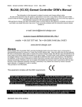
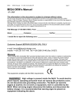
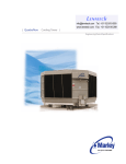
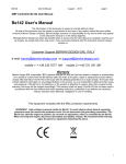
1
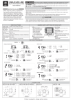
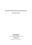
Be-1
User Manual
June - 2015
page 1
Be-1 User Manual
GENERATOR AUTO START KIT
The information in this document is subject to change without notice.
No part of this document may be copied or reproduced in any form or any means without the prior written
consent of Bernini Design Company. Bernini Design assumes no responsibility for any errors which may appear
in this instruction manual.
Customer Support BERNINI DESIGN SRL ITALY
e-mail: [email protected]
Mobile (support): ++39 335 7077148. : ++40 721 241361
Warranty
Bernini Design SRL (hereinafter "BD") warrants that Be-1 shall be free from defect in material or workmanship for a period of 3 years from
the BD delivery date. BD shall, at its option, repair or replace the product without charge. BD shall return the Be-1 to the buyer with the
Default parameters at no extra charge. The buyer shall furnish sufficient information on any alleged defects in the product, so as to enable
BD to determine their cause and existence. If the Be-1 is not defective, or the product is defective for reason other than covered by this
warranty, the buyer will be charged accordingly. This warranty shall not apply if the Be-1 has not been used in accordance with the User
Manual and other operating instruction, particularly if any defects are caused by misuse, improper repair attempts, negligence in use or
handling. The warranty does not include the membrane keyboard (front panel) in case of visible signs of misuse. This purchase is nonrefundable.
WARNING!! High voltage is present inside the Be-1. To avoid electric-shock hazard, operating personnel
must not remove the protective cover. Do not disconnect the grounding connection. The Be-1 can start the
engine at anytime. Do not work on equipment, which is controlled by the Be-1. When servicing the engine,
disconnect the battery and battery charger. We recommend that warning signs be placed on equipment
indicating the above.
1.0 Introduction ...................................................... page 2
2.0 Mode of operation selection .......................... page 2
2.1 OFF mode ........................................................ page 2
2.2 MANUAL mode ............................................... page 3
2.3 AUTO mode .................................................... page 3
2.4 TEST mode ..................................................... page 3
3.0 DISPLAY measurements ................................. page 3
4.0 DISPLAY messages ......................................... page 4
4.10 Alarm messages .......................................... page 4
4.20 Operating messages .................................... page 5
5.0 LED indicators and Test LEDs ....................... page 6
6.0 READING the parameters ............................... page 6
8.0 Alarms, Event History ..................................... page 6
1
Be-1
User Manual
June - 2015
page 2
Section 1.0 Introduction
The Be-1 is a microcontroller based engine protection module. It provides visual indication by means of LEDs
and Display for Fuel Level, Engine & Generator parameters, warnings and shut downs. See figure 1.
Figure 1 Front Panel Layout.
Pushbutton for Alarm Acknowledge
to silence the horn
Pushbutton to
display details
Symbols
(see manual)
Vac
Hz
R.P.M.
Left
Arrow
V
Right
Arrow
4 Digit
Display
Bar
Red LED
indicators
Oil and
Temperature
Alarms
°C
1- - 6
Fuel %
Yellow LED
mode AUTO
Vdc
AUTO
Pushbutton
mode AUTO
TEST
START-ON
°C
V Battery
Alarm
Green LED for
Engine Running
Pushbutton to
START the Engine
External
Alarm or
Emergency
Maintenance
Request Alarm
Fail to Start Overspeed Fuel
Alarm
Alarms
Alarm
Pushbutton STOP
and Mode OFF
selection
Section 2.0 Mode selection
The modes of operation are selected by pushbuttons. Every time the power supply is switched on, the Be1
enters the “OFF” mode, unless the Be-1 was in TEST or AUTO prior to power down. The following table
indicates the available modes.
Mode
OFF
MANUAL
AUTO
TEST
Pushbutton
[O]
[I]
[AUTO]
[AUTO]
LED indicators
All turned Off, dot on display
The yellow LED AUTO is OFF
The yellow LED AUTO is ON
The yellow LED AUTO blinks
Section
2.1
2.2
2.3
2.4
2.1 OFF mode
Push one of the [O] pushbuttons to enter the OFF mode; the Display and LEDs will turn off, a dot on the display
will blink slowly and the alarms will be cleared.
2
Be-1
User Manual
June - 2015
page 3
2.2 MANUAL mode
To start and stop the engine follow the instructions (*):
A) - Push one of the [ I ] pushbuttons until the display indicates the message [MAn] and all LEDs illuminate;
release the button.
B) - Push one of the [ I ] pushbuttons until engine starts. The display indicates the message [. . . .] during the
starting attempt and [! ! ! !] in case of pre-glow. When the engine is running, the green LED 'START-ON' will
illuminate.
C) - To stop the engine, push one of the [ O ] pushbutton until the [StOP] message appears on the display.
If the engine has already stopped, it is possible to cancel the STOP sequence by pressing the [ O ] pushbutton.
Push [ O ] when the engine is not running if you want to shutdown the panel.
Note(*): if the display blinks indicating the message [ALAr.], consult section 8.0 (ALARM, WARNINGS and SHUTDOWNS)
2.3 AUTO mode
Push [AUTO] until the yellow LED on the button will illuminate (*). The engine starts when you activate the
Remote Start and stops when you de-activate the Remote Start input (if provided by your panel
manufacturer). In AUTO mode, the Be-1 will periodically test the engine if programmed by your panel
supplier. During this test, the yellow LED AUTO will continue to blink. Once the Be-1 is in AUTO mode,
push the [AUTO] pushbutton for a short time if you want to select the manual mode (see 2,2). In case of
alarms it is not possible to select the AUTO mode.
Note(*): if the display blinks indicating the message [ALAr.], consult section 8.0 (ALARM, WARNINGS and SHUTDOWNS)
2.4 TEST mode
Enter the AUTO mode (see 2.3). Push and hold for at least 5 seconds, the [AUTO] pushbutton until the yellow
LED will start blinking; the engine will start automatically. To stop the engine, push the [AUTO] or one of the [ O ]
pushbuttons.
Section 3.0 Display measurements
The Be1 features a 4-Digit display and 4 pushbuttons as indicated below.
Display mode
indicators
Display information
pushbutton
Vac
Hz
R.P.M.
V
4-digit
DISPLAY
Alarm acknowledge and horn
silence pushbutton
Left control
display button
Right control
display button
Bar
°C
1- - 6
Fuel %
Vdc
Use [←] and [→] to select a function. Use [ ? ] to display the name of the function. The following table lists the
functions of the display.
3
Be-1
User Manual
June - 2015
Display
indication (*)
Display Function
Generator Voltage
[UXXX]
Generator Frequency
[HXX.X]
page 4
Pushbuttons used Push [ ? ] to indicate the
to select the function name of the parameter
[voLt]
[HErt]
[←] or [→]
Speed R.P.M.
[XXXX]
Battery Voltage Vdc
[bXX.X]
[ bAtt ]
Charger Voltage Vdc
[cXX.X]
[ cHAr]
Oil Pressure Bar
[PXX.X]
[ bAr]
Oil Pressure Bar sensor not used
[P - - - ]
[ bAr]
Fuel Level % (0% up to 99%)
[F XX ]
[FUEL]
Fuel Level sensor not used
[F - - - ]
[FUEL]
Coolant temperature (°C)
Oil Temperature (°C)
Canopy Temperature (°C)
[XXX°]
[°C-1]
[°C-2]
[°C-3]
Coolant temperature not used
Oil Temperature not used
Canopy Temperature not used
[ t1 - - ]
[ t2 - - ]
[ t3 - - ]
[°C-1]
[°C-2]
[°C-3]
Hours-count up to 50.000 h. Over
9999h, the display indicates a dot on the
right. Example: 1234. will mean 12340h
[XXXX]
[Hour]
[ rPM]
(*)NOTE: X indicates a numerical digit, if the measurement is out of range, the display will indicate [ - - -]
Section 4.0 Display messages
The Be1 indicates alarms messages (table 4.10A-B) and operating messages (table 4.20)
!!! WARNING !!! Always consult your supplier or the user manual of the engine. A short description of the alarm follows
below. Recommendations for solving the problem are also indicated.
Alarm messages
The presence of an alarm in the memory is indicated by the message [AlAr.]. Push [ ? ] to display the alarm.
Push [→] to search for other alarms. Push [ACK] to acknowledge the alarm (see also sect. 8.0)
Message
TABLE 4.10A
Description of the Alarm
Button [ ? ]
[ALAr.] Indicates the presence of an alarm. Push [→] and [ ? ] to display the alarm (see the list below)
[OIL.P]
Low Oil Pressure Warning
[Er.01]
Low Oil Pressure Shutdown
[bELt]
Engine Belt Break Shutdown. It energizes if the Charger Alternator fails to
work or if the belt is broken.
Bar indication
Vdc indication
4
Be-1
User Manual
Message
June - 2015
TABLE 4.10-B
page 5
Description of the Alarm
[PicK]
The Be-1 detects a failure of the pick-up.
[bAtt]
Battery Voltage Warning (High or Low)
[°C-1]
[°C-2]
[°C-3]
[°C-4]
[°C-5]
[°C-6]
High EngineTemperature shutdown
High Oil Temperature shutdown
High Canopy Temperature shutdown
Button [ ? ]
None
Vdc indication
°C indication (if
the sensor is not
used, the display
will indicate the
message [S.on])
High Engine Temperature Warning.
High Oil Temperature Warning.
High Canopy Temperature Warning.
[FUEL] Fuel level warning (High or Low).
[Er.06] Low Fuel Shutdown
Programmable Alarm (if provided by your panel
[AL. 01]....[AL. 05]
[Er.07]
% indication
none
manufacturer)
Failure of a Sensor (Oil pressure, Temperatures or Fuel Level)
[InP1] ...... [InP5]
none
[F.StP]
Maintenance Service (when this warning turns on, you are not allowed to
enter the AUTO mode).
Fail to Stop Alarm
[F.Str]
Fail to Start Alarm
none
[Err.]
Memory Failure
none
[ALt]
Alternator Failure
none
[Er.08]
[U.SPd]
[O.SPd]
[Hi-H]
[Lo-H]
[Hi-U]
[Lo-U]
Underspeed
Overspeed Shutdown
none
Speed
Over Frequency Shutdown
Under Frequency Shutdown
Over Voltage Shutdown
Under Voltage Shutdown
Frequency
Voltage ac
TABLE 4.20 Be-1 Operating messages
Message
[rESt]
Description
Message
Description
[CooL]
[. . . .]
The Be-1 is counting the rest timing
(period of time between the starting
attempts)
The Be-1 is starting the engine
[dEL]
Delay time before cranking
[' ' ' ']
The Be-1 is performing the pre-glow
[---]
The measurement is out of range
[StoP]
The Be-1 is stopping the engine
[P0 _][P1 _]
It indicates the coolling down time (the
engine runs off load before stopping)
Indicates that the engine is going to start
or stop following according to the status
of a Remote Switch (consult your panel
manufacturer).
5
Be-1
User Manual
June - 2015
page 6
Section 5.0 LED (solid state lamps) indicators and Test of the LEDs
To test the LEDs and DISPLAY, push and hold the [←] and [→] pushbuttons simultaneously (in OFF or
MANUAL mode). The LEDs and DISPLAY remain energized as long as the pushbuttons are pressed and held
together.
6.0 Reading the parameters
To read the setting of the parameters, follow the instructions:
1) - Press one of the [ O ] pushbutton until the LEDs and display turn OFF.
2) - Push the [←] or [→] pushbutton to select a parameter.
3) - Push [ ? ] to display the setting of the parameter.
4) - Push the [←] or [→] pushbutton to select another parameter. Consult your panel manufacturer for details.
NOTE: if the pushbuttons remain inoperative for more than 2 minutes, the Be-1 turns off the display.
Section 8.0 - Alarms, Warnings and Shutdowns
!!! WARNING !!! Always consult your supplier or the user manual of the engine. A short description of the alarm follows
below. Recommendations for solving the problem are also indicated.
The Be-1 features shutdowns (the engine stops) and warnings (the engine will continue to run) and provides:
A) - a general indication of alarm presence by means of the message [ALAr.] on the display
B) - 4 LEDs to indicate: Oil pressure, Temperature, Fail to start and Over speed shutdown.
C) - display messages indicating warnings and shutdowns (see Table 4.10A-B)
D) - an [ACK] pushbutton to silence the Horn
To silence the HORN, if provided by you panel manufacturer, push the [ACK] pushbutton.
To browse the alarm memory push the [→] pushbutton. To display the details of the alarm, push the [ ? ]
pushbutton. To clear totally the alarm, remove the cause and press the [ O ] pushbutton. The tables 4.10A-B in
the section 4.0 indicate all possible alarms.
Section 8.1 – Event History (INSTRUCTIONS for QUALIFIED PERSONNEL ONLY)
The Be-1 features an Event History register able to record the last 100 shutdown events. To read the contents of
the memory, follow the instructions:
A) – Turn OFF the DC power supply of Be-1 (NOTE!)
B) – Push and hold the [?] pushbutton
C) – Apply the power supply (continue to hold the [?] pushbutton)
D) – Release the [?] pushbutton when the display turns on
E) – The display will indicate the code of the last event ([E 01]). Push the the [?] pushbutton to display the name
of the Event. Alarm events have the same display message used for alarm indication (see secion 4.10A-B)
F) – You can select an event from [E 01] to [E100] using the [←] and [→] pushbuttons. [E100] indicates the
oldest event. [E01] indicates the recent one.
G) – To display the code of the Event, push the [?] pushbutton (see table 4.10).
(NOTE!): in case that the supply switch is not available, consult your panel manufacturer
6