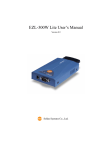
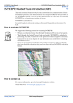
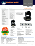
1
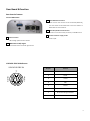
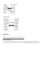
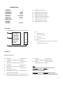
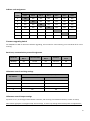
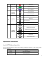
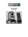
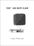
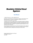
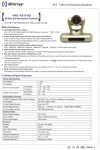
DANNOVO HD USB 3.0 PTZ Video Conference Camera User Manual V 2.3(ENGLISH VERSION) Please read this Manual before set up Camera, and stick to its requirements strictly for Safety reason. Suggest you save this manual for further inquires reference. Content Precautions ........................................................................................................................................................................... 3 Safety Tips ..................................................................................................................................................................... 3 Supplied Accessories ..................................................................................................................................................... 3 Main Features ............................................................................................................................................................... 4 Camera and Lens ................................................................................................................................................... 4 Pan/Tilt Movement ............................................................................................................................................... 4 Rear board connectors .......................................................................................................................................... 4 Electrical Index ...................................................................................................................................................... 4 Structure ............................................................................................................................................................... 4 Rear Board & function................................................................................................................................................... 5 Rear board of camera ............................................................................................................................................ 5 VISCA RS-232C IN Reference ................................................................................................................................. 5 VISCA Out Reference ............................................................................................................................................. 6 Cable Connection info ................................................................................................................................................... 6 Camera to PC connection ...................................................................................................................................... 6 Camera Cascade .................................................................................................................................................... 7 OSD Menu ..................................................................................................................................................................... 7 Self-testing OSD Menu .......................................................................................................................................... 7 Dome OSD ............................................................................................................................................................. 8 OSD Menu ............................................................................................................................................................................. 8 LENS OSD ............................................................................................................................................................... 9 Dip-switch settings ........................................................................................................................................................ 9 Dip-switch over view image .................................................................................................................................. 9 Address code assignment .................................................................................................................................... 10 Firmware upgrading Switch ................................................................................................................................ 10 Baud rate, communication protocol Assignment................................................................................................ 10 IR Remote control receiving settings................................................................................................................... 10 IR Remote control Output settings...................................................................................................................... 10 IR Remote Controller................................................................................................................................................... 11 Operation instruction .......................................................................................................................................................... 13 Joy-stick PTZ Keybaord operation ............................................................................................................................... 13 Special Preset positions function ................................................................................................................................ 14 Specification sheet .............................................................................................................................................................. 15 Installation instruction ........................................................................................................................................................ 17 Wall/Ceiling installation .............................................................................................................................................. 17 Tripod Installation ............................................................................................................................................................... 18 Compatibility ....................................................................................................................................................................... 19 Troubleshooting .................................................................................................................................................................. 19 2 Precautions Safety Tips Please read this manual carefully before use the Camera. To avoid damage from stress, violent vibration, soaking during transportation, storage and installation. Take care of each components of Camera during installation, and install camera at where is affordable enough, to avoid drop or scratches of camera case. Do not apply excessive voltage. (Use only the specified voltage.) Otherwise, you may get an electric shock or a fire may occur. Keep the transmission of RS-485, Video signal away from powerful electromagnetic radiation resources. Do not shoot images that are extremely bright (e.g., light sources, the sun, etc.) for long periods of time. Do not use or store the camera in the specified extreme conditions. (Please refer to specification sheet of camera.) Do not clean camera with active chemical or corrosive detergents, and remove dust or dirt on the surface of the lens with a blower (Commercially available) Do not disassemble any camera components, in case of abnormal operation; contact your authorized dealer or the store where you purchased the product. After long time operation, these components may get machine wear like motor, slip ring, you can contact for repair or change, the local dealer or the shop where you bought this camera. Accessories 1. 1 x 20x Zoom USB 3.0 HD Video Conference Camera; 2. 1 x Power Adaptor; 3. 1 x Remote Controller; 4. 1 x Control Cable; 5. 1 x 3M USB 3.0 Cable, RS-232c to RS-485 cable; 6. 1 x CD User Manual; 7. 1 x Guarantee Card; 8. 1 x Qualified Certificate Card. 3 Main Features Camera and Lens Video CMOS Sensor: 1/2.5 inch super quality HD CMOS transducer Image: 16:9 2.1 Mega pixel Video Format:YUY2|1920x1080P/30, 1280x720/60 Lens zoom: 10x optical zoom, f=4.5-45mm F1.8-2.2 Focus, 1.0Lux at F 1.8 Visual Angle: 5.4°(farness) -52°(nearness) Minimum Illumination: 10LUX White Balance: Auto/Sunlight/Cloudiness/Shade/fluorescence white balance mode Focus: Auto/Manual Iris: Auto/Manual Electronic Shutter: Auto Black light compensation: Auto S/N Ratio: 50dB Pan/Tilt Movement Pan Rotation: 355 degree Tilt Rotation:90 degree Built in Pan/Tilt Motor: Pan speed: 0- 280°/sec Tilt speed: 1°-100°/sec Preset Speed: Pan running: 120°/sec Tilt running: 100°/sec Preset: 9 preset position set by remote Control, 255 preset position set by Keyboard Controller, 4 Patrol lines Rear board connectors High Definition Interface: USB 3.0 Controller Signal Interface: 8 leads mini DIN (VISCA IN, VISCA OUT/RS485) Controller Signal Interface: Dip-switch Pin 7/TTL Signal; Baud Ratio: 9600bps Power supply interface: DC 12V Socket Electrical Index Power supply adapter: 12V DC/2A Input voltage: 12V DC(10.5-14V DC) Input power: 24W(MAX) Structure Material: All-alloy, PC plastic Dimension (Width x highness x depth): 124x120x145mm / 220x175x220mm (NET/PACKAGE) Working environment: Indoor Temperature: -0℃ to +45℃ Storage temperature: -10℃ to +60℃ Color: Silver Gray 4 Rear Board & function Rear board of camera Front of HD Camera 3 VISCA RS232C IN Connector When connect multi cameras to PC via RS-232C (VISCA IN), use serial cable connect VISCA OUT of the first camera to VISCA IN of the second camera. 4 VISCA Out/RS-485 Control Interface Used for connect Chain Daisy of cameras, or RS485 Control. 5 1 DC12V 1.2A Power supply socket USB 3.0 interface Power on/off USB 3.0 high speed transfer interface 2 IR Receiver of R/C Signal To receive IR remote controller signal Sensor VISCA RS-232C IN Reference VISCA RS-232C IN 7 8 5 2 6 3 1 Pin S/N Function 1 DTR IN 2 DSR IN 3 TXD IN 4 GND 5 RXD IN 6 GND 7 IR Commander Signal OUTPUT 8 NO Connection 5 VISCA Out Reference VISCA RS-232C OUT 7 8 5 2 6 3 1 Pin S/N Function 1 DTR OUT 2 DSR OUT 3 TXD OUT 4 GND 5 RXD OUT 6 GND 7 RS-485- 8 RS-485+ Cable Connection info Camera to PC connection Camera 1. DTR IN 2. DSR IN 3. TXD IN 4. GND 5. RXD IN 6. GND 7. IR OUT 8. N.C. Computer 9 Pin 1. CD 2. RXD 3. TXD 4. DTR 5. GND 6. DSR 7. RTS 8. CTS 9. RI 6 Camera 1. DTR IN 2. DSR IN 3. TXD IN 4. GND 5. RXD IN 6. GND 7. IR OUT 8. N.C. Computer 25 Pin 1. FG 2. TXD 3. RXD 4. RTS 5. CTS 6. DSR 7. GND 20. DTR Camera Cascade Camera“A” VISCA OUT Camera“B” VISCA IN 1. DTR OUT 2. DSR OUT 3. TXD OUT 4. GND 5. RXD OUT 6. GND 7. RS485- 1. DTR IN 2. DSR IN 3. TXD IN 4. GND 5. RXD IN 6. GND 7. IR OUT 8. N.C. 8. RS485+ OSD Menu Access OSD menu to understand the features of camera and change the settings. Note: Camera can’t move pan/tilt when OSD menu is displaying on screen. Self-testing OSD Menu There are OSD menu as following when camera start on, and it will be disappear after self-testing completed. Following is the parameter of camera, and different camera module adopted display different OSD menu parameters. 7 INFORMATION ADDRESS BUADRATE PROTOCOL CONTROL LENSTYPE DOMETYPE VENDER VERSION 1 9600 VISCA RS-232C SONY ADDRESS (Camera address) BUADRATE (Camera baud rate) PROTOCOL (PTZ Control Protocol) CONTROL (Camera control type) LENSTYPE (Camera module adopted) DOMETYPE (Camera model No.) VENDOR (Manufacturer name) VERSION (Initial Factory version) 2.3.4.4 Dome OSD Press “DOME OSD” button on remote controller to display: 1 2 &PAN SPEED TILT SPEED SCAN SPEED TOUR PATH TOUR DWELL PROPORTION AUTO REV FRAME ① 20 20 6 1 5 ON P 60HZ Pin Chose OSD menu Move by ↑ or ↓ key ② Parameters ③ Values Chose by ↑ or ↓ key Display OSD parameters, chose by ← or → to change the parameters value of menu. 3 OSD Menu OSD Menu Parameters: PAN SPEED Default value: 30 TILT SPEED Default value: 30 Adjustable tile movement speed scope 1~63 SCAN SPEED Default value: 60HZ Support 60Hz & 50Hz for optional Adjustable pan movement speed scope 1~63 Note: TOUR PATH 60Hz mode, camera output 1080p30 as default, support Default value: 1 1080p@30/25/20/15/10/5, 720p, 800x600, TOUR DWELL(Tour duration time) Default value: 5 PROPORTION (Speed matching) 640x480/60/50/30/25/20/15/10/5; 50Hz mode, camera output 1080p@25 as default, support Tour duration is 1~60 seconds FRAME Default value: 6 Optional tour path at 1~4 Default value: P Image auto flip(positive)/N(upside down)/OFF Adjustable pan movement speed scope 1~63 AUTO REV Default value: ON 1080p@25/20/15/10/5, 720p, 800x600, 640x480/50/25/20/15/10/5; ON means enable speed match function, OFF means not. 8 LENS OSD Access LENS OSD from remote controller, there is OSD menu display on screen and its possible to adjust or change any settings of lens OSD. (Up/down direction key to change the menu, left/right direction key to change the parameters value) 1 OFF NORMAL NORMAL 3 AUTO 206 150 AUTO 1/1 CLOSE 0 &DISPLAY SHARPNESS SATURATION NR WB RGAIN BGAIN AE SHUTTER IRIS BRIGHT 2 3 Lens OSD menu function Camera settings below: DISPLAY Adjustable scope 0~255 Default value: OFF SUPPORT ON/OFF SHARPNESS SATURATION NR (Noise Reduction) IRIS BRIGHT WB (White Balance) Default value: 1/1 Default value: Close Close/F1.4-F22 Default value: 3 Default value: Auto Default value: 0 0 ~ 31 AUTO/MANUAL/OUTDOOR/INDOOR/ONE PUSH/ATW Note: R GAIN (RED RAIN) Shutter, IRIS, BRIGHT only adjustable while AE value set as Default value: 206 MANUAL mode. Adjustable scope: 0~255 SHUTTER SPEED Shutter speed range: 1/1—1/10000 Adjustable Value 0~5 Default value: NORMAL LOW/HIGH Default value: Auto AUTO/MANUAL/SHUTTER/IRIS/BRIGHT Default value: NORMAL LOW/HIGH AE (Auto Exposure) B GAIN (Blue Gain) Default value: 150 Dip-switch settings Dip-switch over view image SW1 SW2 ON 1 ON DIP 2 3 4 5 6 7 8 1 DIP 2 3 4 5 6 底部拨码开关视图 9 Address code assignment SW 1 dip-switch info Address Code DIP-1 DIP-2 DIP-3 DIP-4 DIP-5 DIP-6 DIP-7 1 ON OFF OFF OFF OFF OFF OFF 2 OFF ON OFF OFF OFF OFF OFF 3 OFF OFF ON OFF OFF OFF OFF 4 OFF OFF OFF ON OFF OFF OFF 5 OFF OFF OFF OFF ON OFF OFF 6 OFF OFF OFF OFF OFF ON OFF 7 OFF OFF OFF OFF OFF OFF ON Firmware upgrading Switch Set SW1/DIP-8 as ON for firmware software upgrading, and set OFF for nomal working, must set DIP-8 off for usual working. Baud rate, communication protocol Assignment Baud rate SW 2 DIP-1 Communication SW 2 DIP-2 Protocol SW 2 DIP-3 38400bps ON RS-485 ON PELCO-D ON 9600bps OFF RS-232 OFF VISCA OFF IR Remote control receiving settings R/C Address SW 2 Dip-switch status (Pin 4, Pin 5) DIP-4 DIP-5 default OFF OFF 1 OFF ON 2 ON OFF 3 ON ON IR Remote control Output settings Dip-6 set as “on”, to send signal from Remote controller, and receiving from VISCA IN interface, set OFF as closed; Note: Power-off before to set different dip-switch settings, or inactive of settings with Camera power-on adjustments; 10 IR Remote Controller Front Panel: 1. Reset: Restart Camera and restore to factory default settings 2. Camera Selection Select Camera of IR 1,2,3 3. Preset positions 1-9: preset positions Set: Setting preset position Clear: Clear preset position Call: Call preset position Note: if you need set number 1 preset position, you should press Number key “1”, then press “Set” to setting this position; 4. Zoom in/out Control Zone +: Zoom in -: Zoom out 5. Pan/tilt Control : move up : move down : move left : move right : auto Pan moving 6. Additional Function zone Freeze: image freeze BL: Backlight compensation WB: White Balance AE: Auto Exposure D zoom: Digital Zoom HDMI: swap to HDMI Video output DVI: Swap to DVI video output Format: swap between different format 7. Power supply Switch Switch of stand by and working status 8. OSD Menu Zone Dome OSD: enter Camera OSD Menu Lens OSD: enter Lens OSD Menu 9. Slow Zoom in/out Zone +: Zoom in slowly -: Zoom out slowly 10. Focus Control Zone Auto: auto focus of lens Manual: manual focus of lens Far: focus at far distance objects Near: focus at near distance objects 11. Pan/Tilt Function Zone L-Limit: Set Left limit Scanning position Scan: Enable Boundary scanning R-Limit: Set Right limit scanning position Home: Camera Home position Tour: Enable Patrolling Rev: Image auto-flip 11 S/N Regional 1 Reset 2 Camera ID Chose Keynote Restart Camera and back to default Factory settings. 1 ~ 3 1 3 Preset position function area ~ 9 Set Clear Call 4 Fast-speed Zoom in/out functions + Chose camera according to your Remote control Chose serial no. of preset position To “Set” as preset position To “Clear” preset position To “Call” preset position Zoom in of camera Lens Zoom Fast - Zoom out of camera lens Move camera up-side Move camera down-side 5 Pan/Tilt control Move camera go left Move camera go right Enable Pan movement scanning Freeze Image Freeze BL Backlight compensation WB 6 White Balance AE Auto Exposure DZOOM Digital Zoom Auxiliary HDMI DVI Format Swift as HDMI Video output (not available with this camera) Swift as DVI Video output (not available with this camera) Swipe different video formats (not available with this camera) 12 7 8 9 10 11 Power on/off Power-on/off Dome Login DOME OSD Menu Lens Login Lens OSD Menu + Zoom in slowly speed OSD Menu Slow speed Zoom in/out Lens Focus adjustments Pan & Tilt Function area Zoom Slow - Zoom out slowly speed Auto Auto focus automatically Manual Manual focus Far Lens zoom in far end Near Lens zoom in Near end L-Limit Set Left points for boundary scanning Scan Enable Scanning automatically R-Limit Set Right limit point for Boundary scanning Home Home position of Camera Tour Enable Touring Rev Image Up-side down option Operation instruction Joy-stick PTZ Keyboard operation To use joy-stick PTZ keyboard to control Camera including, pan/tilt/zoom movement, set Tour scanning, enable boundary scanning, etc. option function turn up Down-side movement turn down Up-side movement 13 turn left Left movement turn right Right movement Rotate left Zoom in Rotate right Zoom out Special Preset positions function Preset position No. Functions 76 Enable stand-by status 77 To display Self-testing menu on screen 90 Image up-side down 91 Login system OSD Menu 92 Set Left limit position of scanning 93 Set right limit position of scanning 94 Restart Camera and return default settings 95 Call Lens OSD Menu of Lens 96 Home position 97 Enable regional Pan scanning 98 Enable Tour scanning 99 Enable 360 degree Horizontal scanning 14 Specification sheet Model No. Image Sensor DN-HDC08B-CN Sensor 1/3" CMOS 2.1 Mega Pixel Effective Pixels Minimum Scene Illumination 2.1 Megapixel Color: 0.1Lux,Black/White: 0.01Lux White Balance Auto/Manual Gain Control Back-light compensation Auto On / Off E-Shutter 1/30s~1/10000S S/N Ratio > 50db Focus f=5-50mm Iris Auto/Manual Zoom 10x Optical Zoom Lens View Angle 52° Video Output USB 3.0 Video Output Mode Video Format:YUY2|1920x1080P/30, 1280x720/60 Communication Interface RS-485,EIA/RS232C (Bidirectional) Communication Control Protocol PELCO-D,VISCA Baud Rate 9600/38400bps Tour 4 Line Preset Position 64 LCD Display Optional (Needs OEM) Power on State Auto Scan or tour Speed Matching OSD Menu Support To change parameters of camera or camera module from OSD Menu Image Auto Flip When tilt movement over 90 degree(Option) Pan Speed 1-280 degree per second Tilt Speed 1-100 degree per second 15 Pan Rotation Angle 0~355degree Tilt Rotation Angle 90 degree Auto Pan Scan Support auto pan scan Boundary Scan 0-359 degree (programmable) Remote Controller IR wireless control P/T/Z Power Supply DC12V±10%,1.2A Working Temperature 0-60℃ Environment Humidity 0-95%RH 16 Installation instruction Wall/Ceiling installation Mount kits provided with Camera in the package. 17 Tripod Installation To fix the round accessory on bottom board of camera, to match 2 screw position on the bottom board; To match the Tripod on bottom of camera; 18 Compatibility As we tested with Amcap S/W, Skype, Microsoft Lync, VSEE, Vidyo, DEBUT Software, most of them are Video Conferencing system application, and it works perfect; Troubleshooting Before request service to serviceman or manufacture, it can according to below methods to remove failures, if still can’t be solved, please contact to distributor or manufacture for help. Fault Phenomenon There is no power to camera. The video of camera cannot be displayed on the screen. It’s unable to Pan, Tilt and zoom camera. Reason Solution The power has been prevented between adaptor and AC or DC IN 12V has not been connected to camera. Please check the connector between camera and power, fixed the power adaptor to camera. Power switch was set to OFF. Please set power switch to ON. Video cable is bad contact. Check the connection between video cable, camera and monitor; fix the connector on each end. Exposure setting is not correct on camera. Change it to right exposure settings. Menu was displayed on monitor. Pan and tilt range was limited. Re-operate after exit menu. Remote control is not working. The “camera select” button on the remote control is not match with “IR select” switch number. Choose the correct “IR number to meets camera. It was not been controlled via VISCA when camera connect to PC. The connection between PC and camera is wrong. Make sure it is a correct connection between camera and PC. (Reference to camera connection.) The camera completely. is not working select” Pull up the power, and wait a few minute to connect power again. Or power off the camera, then restart after a moment. 19