1
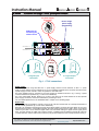
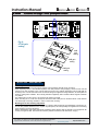
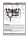
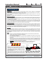
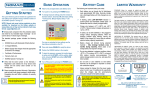
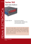
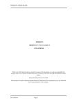
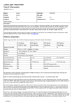
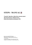
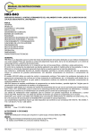
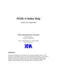
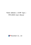
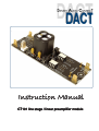
Instruction Manual
CT101 line stage / linear preamplifier module
Instruction Manual
CT101
DANISH AUDIO CONNECT
2-channel line stage / linear preamplifier module
CONTENT
Unpacking
Connections
Definitions
Power supply
Signal input
Signal output
Volume control
Gain setting
Please make sure to read through
all of this Instruction Manual before
connecting your CT101.
Power supply
Volume control
Gain setting
Mounting / assembling
Other information
Side view
Headphones
Balanced preamplifier
6-channel A/V audio
DC offset
Hints
SMD components
X
Do not bend the CT101 PCB.
Bending it may easily damage the
SMD components on the rear side.
Caution
UNPACKING
Thank you for purchasing this Danish Audio ConnecT product.
CT101 is a ready-made 2-channel linear audio preamplifier module built on a compact PCB. CT101 is specifically
designed for using with a DACT stepped audio attenuator as volume control. Connecting CT101 to input/output
sockets and an external power supply will provide you with a high quality, no-nonsense, active preamplifier.
Your CT101 purchase includes
1 pc. CT101 2-channel linear preamplifier module
1 mounting set consisting of
2 pcs. M3 stainless steel screws
2 pcs. M3 stainless steel nuts
2 pcs. M3 brass spacers
4 pcs. stainless steel washers
2 pcs. power supply connectors including wires
3 pcs. jumpers for using CT101 with one power supply
1 pc. instruction manual
We recommend that you make sure to keep all of the above items after unpacking your CT101, as everything will
prove useful to you when mounting and connecting your CT101.
CONNECTIONS
Definitions
‘Marking’ refers to the text printed on the CT101 Printed Circuit Board:
Marking
IN 1
IN 2
OUT 1
OUT 2
P1, 1 2 3
P2, 1 2 3
+/-
Definition
Signal input, channel 1
Signal input, channel 2
Signal output, channel 1
Signal output, channel 2
Attenuator, channel 1
Attenuator, channel 2
Power supply to one or both of the 3-way connectors
Please also refer to Fig. 1.
Danish Audio ConnecT does not authorize or warrant the use of any of it’s products in life support devices and/or systems. Danish Audio ConnecT shall
not be liable for any damages to connected equipment like amplifiers and loudspeakers.
Copyright © 2001, Danish Audio ConnecT A/S, Denmark. All rights reserved.
http://www.DACT.com
Revised 28 August 2002
1
Instruction Manual
CT101
DANISH AUDIO CONNECT
2-channel line stage / linear preamplifier module
2 x power supply
connectors
Dual or single
power supply
'programming'
PCB holes for
connecting the
volume control
+
© 1999 Danish Audio ConnecT
2
3
12
P1
CT101
Audio Buffer
IN
2
Channel 2
IN
1
Channel 1
1
Gain
6
+
1 2 3
P2
12
OUT OUT
2
1
6
-
2 x Gain
settings
SIGNAL
Signal GND
SIGNAL
2 x signal input
connectors
Signal GND
2 x signal output
connectors
Fig. 1. CT101 connections
Power supply
CT101 is designed for using with either one +/- power supply common for both channels, or with a +/- power
supply for each channel. The two channels of CT101 are completely separated on the PC Board. Therefore, when
a power supply for each channel is used, the operation is true dual-mono.
The power supplies must be connected to the 3-way square pin headers as shown in fig. 1 and fig. 2 (exact
connector dimensions specified in fig. 3 of the CT101 Datasheet).
The colour codes (RED, BLACK, BLUE) in fig. 2 refer to the colours of the wires attached to the two separate
power supply connectors, which are included when purchasing a CT101.
For more details please refer to the POWER SUPPLY chapter on the following pages.
Signal input
The input terminals are marked IN 1 and IN 2 on the CT101 PCB, and consists each of a round pin terminal and a
flat tab terminal (specified in fig. 3 of the CT101 Datasheet).
Generally, we recommend connecting the inputs with screened cables. The longer the input cables are, the more
important is the screening. If the distance between the input sockets and the CT101 PCB is short, non-screened
cables may be used. For non-screened signal cables, we recommend twisting the signal and the signal ground
wires. For each channel, the cable outer conductor (screen - braid/foil) must be soldered to the flat tab connector
(~’spade terminal’), and the cable centre conductor (core) must be soldered to the round pin terminal. See fig. 3.
Danish Audio ConnecT does not authorize or warrant the use of any of it’s products in life support devices and/or systems. Danish Audio ConnecT shall
not be liable for any damages to connected equipment like amplifiers and loudspeakers.
Copyright © 2001, Danish Audio ConnecT A/S, Denmark. All rights reserved.
http://www.DACT.com
Revised 28 August 2002
2
Instruction Manual
CT101
DANISH AUDIO CONNECT
2-channel line stage / linear preamplifier module
+
Positive supply voltage
RED
0
Zero supply voltage
BLACK
-
Negative supply voltage
BLUE
Fig. 2. CT101 power supply connections
Signal output
The output terminals are marked OUT 1 and OUT 2 on the CT101 PCB, and consist each of a round pin terminal
and a flat tab terminal (specified in fig. 3 of the CT101 Datasheet).
Generally, we recommend connecting the inputs with screened cables. The longer the input cables are, the more
important is the screening. If the distance between the input sockets and the CT101 PCB is short, non-screened
cables may be used. For non-screened signal cables, we recommend twisting the signal and the signal ground
wires. For each channel, the cable outer conductor (screen - braid/foil) must be soldered to the flat tab connector
(~’spade terminal’), and the cable centre conductor (core) must be soldered to the round pin terminal. See fig. 3.
Volume control
The CT101 PCB features holes and connections for a volume control for each of the two channels, marked P1 and
P2. See fig. 1.
The layout is made, so either a DACT stereo CT2 or a DACT stereo CT1 stepped attenuator will fit directly.
For more details please refer to the VOLUME CONTROL chapter on the following pages.
Gain setting
The gain of CT101 can easily be set at either 0dB (‘buffer-mode’), 6dB or 12dB. Please see fig. 1.
For more details please refer to the GAIN SETTING chapter on the following pages.
Flat tab connector
Inner cable conductor
Outer cable conductor (screen)
Outer cable insulation
Round pin terminal
Insulation between cable
inner and outer conductors
CT101 PCB
Two solder joints
Fig. 3. CT101 audio signal input/output connections
Danish Audio ConnecT does not authorize or warrant the use of any of it’s products in life support devices and/or systems. Danish Audio ConnecT shall
not be liable for any damages to connected equipment like amplifiers and loudspeakers.
Copyright © 2001, Danish Audio ConnecT A/S, Denmark. All rights reserved.
http://www.DACT.com
Revised 28 August 2002
3
Instruction Manual
CT101
DANISH AUDIO CONNECT
2-channel line stage / linear preamplifier module
POWER SUPPLY
Requirements
CT101 is delivered without power supply in order to let the user decide for and experiment with his own power
supply design. For information about available power supplies from DACT, please visit http://www.DACT.com.
CT101 requires a +/- DC power supply to operate. Maximum supply voltages and recommended supply voltage
are specified in Table 1 of the CT101 Datasheet.
For typical applications, where CT101 is used to drive loads of 5kOhm or greater, the recommend supply voltage is
between +/-17VDC and +/-35VDC.
If CT101 is used to drive loads with lower impedance (for instance headphones), it is advised to limit the supply
voltage to between +/-17VDC and +/-24VDC. Otherwise, the output devices of CT101 may become overheated.
Under typical use, driving a 5kOhm or greater load, CT101 draws less than 3mA per channel. Driving lower
impedances will increase the supply current.
Please make sure to be very careful about connecting the power supply correctly.
Connecting the power supply
An easy and convenient way to connect the power supply is to use one or both of the 3-way connectors, which are
included when purchasing a CT101, see fig. 4. Each of them has three wires attached, and they fit the two 3-way
pin connectors on the CT101 PCB (shown in fig. 2). Positive and negative supply connections are printed on the
PCB as + and -. The red wire must be connected to the positive supply voltage, the blue wire to the negative
supply voltage, and the black wire to zero supply voltage. Make sure to connect the power supply polarity correctly.
Wrong polarity may destroy CT101 and connected equipment. See also the CAUTION paragraph on the last page.
Using an existing power supply
One possibility of powering CT101 is from existing audio equipment, like power amplifiers, CD-players, etc. This is
often possible because CT101 requires only little supply current, and because it accepts a wide supply voltage
range. Especially when building CT101 into existing equipment, this way of powering it is an option.
Before experimenting with ready-made audio equipment, please observe that the warranty of the equipment will
usually no longer be valid. We recommend that only trained technicians make this kind of ‘surgery’.
Audio power supply
Although CT101 has two voltage regulators for each channel built-in, it is recommend paying attention to the
quality of the external power supply. In spite of the built-in voltage regulators, the quality of the external power
supply has significant influence on the sound quality of CT101. In our view, a good audio supply for instance
features:
ability to deliver current pulses with high speed
low output resistance far beyond the audio frequency range
low noise
high ripple suppression
Due to the low power consumption of CT101, battery operation is a possibility. Sound testing of CT101 operated
by batteries was including in the design phase, and the results proved excellent. Either rechargeable or nonrechargeable batteries may be used.
For most types of power supplies, including batteries, we recommend adding some high quality reservoir
electrolytic capacitors. It is important that the reservoir capacitors have low ESR, also at high frequencies. Some
electrolytic capacitors are specially optimized for higher frequencies, and have ESR specified at 100kHz. We
recommend using these types, for instance with capacitance values of 2,200uF each. The reservoir capacitors
should be mounted on the supply lines, as close to CT101 as possible, so only short wires are required. A
simplified schematic is shown in fig. 5. Examples of suited reservoir capacitors are
RS Components, part no. 394-923
Farnell, part no. 108-844
+
0
-
Fig. 4. Power supply cables included with CT101
Danish Audio ConnecT does not authorize or warrant the use of any of it’s products in life support devices and/or systems. Danish Audio ConnecT shall
not be liable for any damages to connected equipment like amplifiers and loudspeakers.
Copyright © 2001, Danish Audio ConnecT A/S, Denmark. All rights reserved.
http://www.DACT.com
Revised 28 August 2002
4
Instruction Manual
CT101
DANISH AUDIO CONNECT
2-channel line stage / linear preamplifier module
+ supply voltage
+
+
0 supply voltage
0
-
+
- supply voltage
Fig. 5. Connecting low impedance
power supply reservoir capacitors to CT101
Dual mono (dual power supply)
© 1999 Danish Audio ConnecT
2
3
12
Gain
6
+
1 2 3
P2
12
OUT OUT
2
1
1
P1
CT101
Audio Buffer
IN
2
WARNING!
If the CT101 is power supplied incorrectly
with only a positive or only a negative
supply-half connected, a DC voltage of
several Volts may occur on the output
terminals OUT 1 and OUT 2. See also the
CAUTION chapter on the last page of this
manual.
+
6
IN
1
For optimal performance (especially
benefiting
channel
separation),
we
recommend using a separate power
supply for each CT101 channel (dual
mono). Both power supplies should be
identical and meet the above-mentioned
requirements.
When purchasing a CT101, the package
includes 3 pcs jumpers. In case a +/power supply is used for each channel, the
three jumpers are not used. In case one
power supply is used common for both
channels, the three jumpers must be
mounted on the front side, and soldered in
both ends to the backside of the CT101
PCB. See fig. 6. If a common power
supply is used, it may be connected to the
3-way connector of either channel 1 or
channel 2.
-
or
Using one power supply
for each channel: The
jumpers are not mounted
Using one common power
supply for both channels:
The jumpers are mounted
Fig. 6. CT101 jumpers for using
one or two +/- power supplies
VOLUME CONTROL
Principally CT101 can be used with any volume control. However, we recommend using only high-grade volume
controls. Only the best volume controls will not influence the sound quality of CT101. Especially, we recommend
using a DACT stepped audio attenuator with CT101. The CT101 PCB layout makes it possible to fit either a DACT
CT1 stereo or a DACT CT2 stereo attenuator just by soldering 6 connections on the backside of the PCB.
The best way is to solder the volume control directly into the CT101 PCB, obtaining the shortest possible signal
path and the best sound. If this is not possible, DACT offers a connection kit that does not require soldering on the
attenuator. The connection kit includes 3 x 30cm (3 x 12”) wires. For longer distances, using shielded wires is
recommended.
Danish Audio ConnecT does not authorize or warrant the use of any of it’s products in life support devices and/or systems. Danish Audio ConnecT shall
not be liable for any damages to connected equipment like amplifiers and loudspeakers.
Copyright © 2001, Danish Audio ConnecT A/S, Denmark. All rights reserved.
http://www.DACT.com
Revised 28 August 2002
5
Instruction Manual
2-channel line stage / linear preamplifier module
+
3
12
P1
IN
2
CT101
Audio Buffer
1
2
Gain
6
+
1 2 3
P2
12
1
OUT OUT
2
1
6
IN
1
-
2
3
Fig. 7.
Using CT101
without volume
control
Jumper
connecting
'2' with '3'
+
© 1999 Danish Audio ConnecT
3
12
P1
IN
2
CT101
Audio Buffer
1
2
Gain
6
+
1 2 3
P2
12
Resistors (one per
channel) may be
connected either
across the input
terminals or between
the volume control
points '1' and '2'.
OUT OUT
2
1
6
IN
1
Instead of mounting the volume control apart from
CT101, a better solution is to fit both together inside
the enclosure, and extend the volume control’s
shaft. DACT offers shaft extension kits for
attenuator shaft extension purposes.
Make sure always to attach the volume control to
the equipment enclosure, to a bracket, or similar.
The volume control SHOULD NOT be fastened only
by soldering it to the CT101 PCB.
Volume controls are available with many different
resistances. DACT offers stepped attenuators in 10,
20, 50, 100, 250 and 500kOhm. It is our experience
that the lower resistance volume controls sound
better than high resistance volume controls when
used with CT101. Therefore, we normally
recommend using a 10kOhm attenuator with CT101
There is one more concern when deciding which
attenuator resistance to use for CT101: The
attenuator is connected directly across the audio
signal input. Therefore, the attenuator resistance
determines the input resistance of the complete unit
So for instance a 10kOhm attenuator will fix the
CT101 input resistance at 10kOhm.
When using a DACT attenuator with CT101, the
attenuator must be soldered to the CT101 PCB in
the right way. Looking at CT101 with the audio
input connectors pointing to the left, and with the
component side upwards, the DACT attenuator
must be mounted so the attenuator shaft points
towards you. See also fig. 10.
If a metal enclosure is used, usually the attenuator
will be fastened directly to a part of the enclosure,
so the attenuator click-house is connected to
chassis ground (fig. 10). In case the attenuator
click-house is not connected to chassis ground
when mounted, there should be made a separate
connection. See also the http://www.DACT.com
attenuator pages.
In certain cases, it is not required to use a volume
control with CT101. If there is no volume control
connected to CT101, a jumper must be mounted in
each CT101 channel, see fig. 7. In this way, the
input resistance is 100Mohm. However, usually a
100Mohm input resistance is not recommendable
for audio applications. Therefore, two resistors may
be added to reduce the input resistance. See fig. 8.
For instance, two high quality 10kOhm resistors
may be added (one per channel) to set the input
resistance at 10kOhm.
© 1999 Danish Audio ConnecT
CT101
DANISH AUDIO CONNECT
-
1
2
3
Jumper
connecting
'2' with '3'
Fig. 8. Using CT101 without volume
control but with resistors controlling the
input resistance
GAIN SETTING
CT101 offers gain settings of 0dB, 6dB or 12dB. 0dB gain setting is referred to as ‘buffer mode’.
The gain is set individually for the two channels, but usually the gain is set at the same level.
Gain setting is made without soldering or using any tools. The gain setting jumpers may be removed or
repositioned by hand. Just remove it by pulling it away from the PCB. See fig. 9 for guidance.
It is recommended to choose the lowest usable gain setting, as the CT101 specifications at lower gain are slightly
better than at the higher gain settings.
Danish Audio ConnecT does not authorize or warrant the use of any of it’s products in life support devices and/or systems. Danish Audio ConnecT shall
not be liable for any damages to connected equipment like amplifiers and loudspeakers.
Copyright © 2001, Danish Audio ConnecT A/S, Denmark. All rights reserved.
http://www.DACT.com
Revised 28 August 2002
6
Instruction Manual
CT101
DANISH AUDIO CONNECT
2-channel line stage / linear preamplifier module
+
© 1999 Danish Audio ConnecT
12
Gain
6
+
1 2 3
P2
12
OUT
2
3
P1
IN
2
CT101
Audio Buffer
IN
1
2
1
OUT
1
6
-
Fig. 9.
CT101 gain
setting
0dB
gain
setting
6dB gain
setting
12dB gain
setting
MOUNTING / ASSEMBLING
Mounting hardware
To protect CT101 against dust and larger particles, it should always be built into an enclosure.
When unpacking CT101, it is mounted in a plastic cover that protects it during shipping. Loosen the two nuts and
extract CT101 from the plastic cover. In most cases, the screws, nuts, washers and spacers can be used again for
mounting CT101 in its final enclosure. We recommend using the supplied mounting hardware, as all the parts are
made of “audio grade” materials. The mounting hardware supplied by DACT contains neither magnetic materials
nor plastics.
The easiest way to mount CT101 is by using the two holes in the PCB.
When mounting CT101, make sure to keep the PCB traces and solder joints on the back side at a safe distance
from electrically conducting materials, in order to avoid short-circuiting.
Building CT101 into existing equipment
One possibility is to build CT101 into the enclosure of existing audio equipment, like preamplifiers, CD-players, etc.
This is often possible because CT101 requires only little space, and could possibly be supplied from the existing
power supply in the ‘host’ equipment.
Before experimenting with ready-made audio equipment, please observe that the warranty of the equipment will
usually no longer be valid. We recommend that only trained technicians make this kind of ‘surgery’.
Danish Audio ConnecT does not authorize or warrant the use of any of it’s products in life support devices and/or systems. Danish Audio ConnecT shall
not be liable for any damages to connected equipment like amplifiers and loudspeakers.
Copyright © 2001, Danish Audio ConnecT A/S, Denmark. All rights reserved.
http://www.DACT.com
Revised 28 August 2002
7
Instruction Manual
CT101
DANISH AUDIO CONNECT
2-channel line stage / linear preamplifier module
Chassis ground
connection
2
Capacitor
reservoir using
4 pcs. 2,200uF
capacitors
+/- DC power supply
connections, separate
for each channel
Audio signal
input
1
Audio signal
output
2
+
+
2,200uF / 35V
+
2,200uF / 35V
+
1
Cable outer
conductor
(screen)
connections
2,200uF / 35V
2,200uF / 35V
+
© 1999 Danish Audio ConnecT
3
12
P1
IN
2
CT101
Audio Buffer
IN
1
2
Gain
6
+
1 2 3
P2
tor
ua
n
te
At
Stainless steel screws,
washers, nuts and
spacers included with
CT101
12
OUT OUT
2
1
6
1
Connector body
isolated from
enclosure on
both sides
Cable centre
conductor
connections
-
Metal enclosure
CT101 PCB
Attenuator click-house
Fig. 10. CT101-based preamplifier in metal enclosure
Materials considerations
DACT believes that magnetic materials and certain plastic materials should not be used for any parts of audio
electronics equipment. Magnetic materials are associated with hysteresis losses when exposed to varying
electrical/magnetic fields. Plastics are associated with dielectric losses when exposed to varying electrical fields,
although some plastics do have very low losses. Both phenomena introduce non-linear distortion, which disturbs
low-distortion high-end audio equipment.
Some times plastic enclosures are preferred because of their electrical non-conducting properties. In that case, we
recommend using a plastic type with low dielectric loss, like for instance Teflon®, polystyrene and polypropylene.
Otherwise, we recommend using an enclosure made of a non-magnetic metal. Easily and cheaply available are
enclosures made of aluminium, but also copper and brass are suited materials. Metal enclosures are usually
grounded and they reduce electrical fields radiated into the audio electronics, thereby reducing audible noise.
Mounting CT101 in a metal enclosure
A very typical way to mount CT101 is in a separate metal enclosure. As an example see fig. 10. For non-balanced
audio equipment it is very common to use RCA sockets for audio signal input/output. To avoid hum, make sure
that the body (signal GND) of the RCA sockets do not make electrical contact with the metal enclosure. Instead, as
shown, make a GND connection from one of the audio input signal grounds to the chassis.
Danish Audio ConnecT does not authorize or warrant the use of any of it’s products in life support devices and/or systems. Danish Audio ConnecT shall
not be liable for any damages to connected equipment like amplifiers and loudspeakers.
Copyright © 2001, Danish Audio ConnecT A/S, Denmark. All rights reserved.
http://www.DACT.com
Revised 28 August 2002
8
Instruction Manual
CT101
DANISH AUDIO CONNECT
2-channel line stage / linear preamplifier module
OTHER INFORMATION
Headphones
Headphones may be connected directly to the output sockets of CT101, at OUT 1 and OUT 2. As headphones
usually have lower impedance than 5kOhm, the supply voltage for CT101 should be limited to no more than +/24VDC. See also the POWER SUPPLY chapter in this manual.
The best results may be obtained using headphones with at least 600ohm resistance. Make sure to connect the
phases correctly.
WARNING! Avoid playing with the headphones at so loud volumes, that your hearing is permanently affected.
Balanced preamplifier
CT101 may be used for balanced audio signals. If so, one balanced audio channel requires both channels of a
CT101. The positive (non-inverted) signal is connected to one channel and the negative (inverted) signal is
connected to the other channel.
If a balanced stereo preamplifier is required, two CT101s have to be used, one for each channel. As volume
control, we recommend using a 4-deck DACT stepped attenuator. If the two CT101s are mounted behind each
other, the 4-deck attenuator will fit directly into both PCBs. For more information we recommend reading the
application note on using CT101 to build a multi-channel active preamplifier.
6-channel A/V audio
CT101 may be used for 6-channel A/V audio signals. Then three CT101s have to be used, for instance one for the
front channels, one for the rear channels and on for the center and the sub channels. As volume control, we
recommend using a 6-deck DACT stepped attenuator. If the three CT101s are mounted behind each other, the 6deck attenuator will fit directly into all three PCBs. For more information we recommend reading the application
note on using CT101 to build a multi-channel active preamplifier.
DC offset
All DC-coupled equipment always has a small DC offset at the output. CT101 typically has a DC offset around
1mV at 0dB gain setting. This level is usually not a problem. If a DC-coupled amplifier follows CT101, it must be
evaluated if the DC offset level at all points in the chain of audio equipment is at acceptable levels. Especially the
DC level across the loudspeaker terminals is critical. To remove the DC offsets, audio grade coupling capacitors
may be added.
Hints
1.
2.
3.
4.
5.
6.
7.
Power ‘on’/’of’ must be switched with a double-pole switch to ensure that both the positive and the
negative supply voltage are switched simultaneously.
DC-coupled power amplifiers represent a potential risk for loudspeakers. Be careful to check DC levels
before connecting the speakers.
Do not flex the CT101 PCB. This may damage the SMD components by cracking and/or breaking their
solder joints.
When turning CT101 on for the very first time make sure to connect its outputs to an amplifier that has a
volume control itself. Turn the volume fully down, then connect and turn on CT101. Gradually turn up the
other amplifiers volume in order to prevent wrong wiring etc. from damaging your other audio equipment.
Maintenance. CT101 does not require any maintenance.
Modifications. We do not recommend modifying your CT101 as it is already optimized.
Service. If service is required, contact your dealer and arrange for further action.
Side view
Please be very cautious when connecting the CT101 to your audio
equipment. CT101 is an active module, and in case of wrong
connections or in case of failures, there is a risk of getting up to 1415V DC offset on the output of CT101. High levels of DC offset may
cause damages to power amplifiers, loudspeakers or any other
connected equipment. Special attention is required when using DCcoupled power amplifiers.
Before connecting the outputs of CT101, make sure of proper
operation and check the DC-voltage at the CT101 outputs. The DC
voltage should be no more than a few mVs. In case of any doubt,
start out using a coupling capacitor in series with the CT101 output.
SMD components
X
Do not bend the CT101 PCB.
Bending it may easily damage the
SMD components on the rear side.
Danish Audio ConnecT does not authorize or warrant the use of any of it’s products in life support devices and/or systems. Danish Audio ConnecT shall
not be liable for any damages to connected equipment like amplifiers and loudspeakers.
Copyright © 2001, Danish Audio ConnecT A/S, Denmark. All rights reserved.
http://www.DACT.com
Revised 28 August 2002
9