1
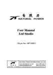
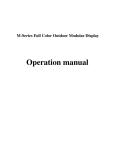
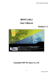
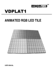
ROPIX P18
Index
ROPIX P18 Hardware ................................. 3
I. ROPIX P18 Profile Overview ........................................................................................... 3
II. Parameter .............................................................................................................................. 5
Sending Card ..................................................................................................................... 6
Receiving Card .................................................................................................................. 8
Maintenance Tools ............................................................................................................ 8
III. ROPIX P18 Installation ...................................................................................................... 9
Cabinet Assembly ............................................................................................................. 9
Controlling System Installation ................................................................................... 10
a) Cable connection method ............................................................................................ 10
b) Install Sending Card ................................................................................................... 10
ROPIX P18 Software................................ 12
I.
II.
Software Installation ....................................................................................................... 12
Software setup ................................................................................................................. 13
a. Receiver Setup............................................................................................................. 13
b. Display Connection Setup ........................................................................................... 18
2
ROPIX P18
ROPIX P18 Hardware
I.
ROPIX P18 Profile Overview
Pic 1. Overview
A cabinet is composed of 64 LED Strips, 64 pixels on horizontal, and 32 pixels on
vertical; the dimension is 1152mm×576mm.
3
ROPIX P18
Pic 2. Front-side Overview
Pic 3. Back-side Overview
1- Upper Beam
2- Bottom Beam
3- Left Side-board
4- Right Side-board
5- Left Side-fast lock1
6 -Left Side-fast lock2
7-Right Side-fast lock1
8-Right Side-fast lock2
9-Left Davit
10-Right Davit
11-Handle
12-Handle Holder
13-Upper Buckle
14-Bottom Buckle
15-LED Strips
16-Upper Beam2
17-Signal Switch
18-Signal Indicator and Tester
19-Fuse
20-AC Cable with Female Connector
21-AC Cable with Male Connector 22-Left Fast lock
23-Right Fast lock
4
ROPIX P18
II. Parameters
Characteristic
Value
Unit
Condition
Supply voltage
220
v
AC
Maximum power consumption
250
w/m2
-
Operating power consumption
90
w/m2
-
Pixel pitch
18
mm
-
Brightness
≥4000
cd/m2
-
View angle
120
deg.
120(vertical)
Gray scale
4096
Level
Refresh frequency
900
Hz
Frame frequency
60
Hz
View distance
15~180
m
-
Operating temperature
-20~60
℃
-
Operating humidity
10~90
%
-
Maximum control distance
100
m
without relaying
5
-
ROPIX P18
II.
Accessories introduction
Sending Card
Pic 4 Sending Card
The Sending Card is to transmit data to receiving card on display. It
has four kinds of interface, which are DVI interface, additional
function interface, data output interface, and external power
interface.
DVI interface: DVI interface is a data input port, which is exactly
designed for Graphic card signal transferment.
Additional function interface: it is to control grey level, LED display
power switch, locking display, and showing the area setup. To operate
with LED Display, this interface is to connect with serial port for
receiving card setup.
Data output interface: There are two output interface on each sending
card. It is to connect with Receiving Card via pin-to-pin CAT5 UTP (4
6
ROPIX P18
unshielded twisted paired). The sequence of the twisted paired is:
white-orange, orange, white-green, blue, white-blue, green, white-brown,
and brown. It is shown as below. Both sides are the same sequence.
Data cable RJ45 connection sequence
External power interface: The power comsumption for sending card is
5V. If sending card is working without support from computer, external
5V power supply is needed to link to this interface.
Besides, there are
two indecators (one red, one green) next to this interface. Red indecator
represents power supply, and green indecator represents data transferment.
If the card is working properly, red indecator is on and green indicator is
supposed to be flashing.
7
ROPIX P18
Receiving Card
Receiving card is building-in inside of each cabinet. The function is to
receive data from sending card via Cat5 cable, then transfer data to led
display signal. 5V power supply is required as well. The necessary setup
is needed when a new receiving card is placed.
Maintenance Tools
Pry bar
8
ROPIX P18
The tools are shown as above. Each ROPIX P18 cabinet is composed of
32 LED Strips. All LED strips are fixed on cabinet by two buckles. When
LED strips replacement is needed, before removing LED strips, pry bar is
needed to pry strips out smoothly without any damage.
III. ROPIX P18 Installation
Cabinet Assembly
The design of ROPIX P18l is focused on fast and easy assembly. Two
sets of bottom fast locks and two sets of side fast locks are adopted.
Bottom fast lock
9
ROPIX P18
As shown before, P18 LED curtain contains two fast locks on each side
of the bottom. The ROPIX P18 needs to use these two fast locks to fix all
panels on vertical.
Controlling System Installation
a) Cable connection method
b) Install Sending Card
Fig 0-1
The Sending Card is installed in an unused PCI socket of control
computer. Additional function interface is connected to Serial port. And
10
ROPIX P18
two signal output ports, U port and D port will connect ROPIX P18 via
cat5 cable.
UTP (another side
connects to the
Receiving Card)
Digital Visual Interface DVI
Connect to the
Serial port of
computer
Connect to the
DVI-out of
computer
Serial port
Sending card cable connection method
Three cables will be linked to sending card while the certain wall is
working, which are DVI cable, Serial port cable, and Cat5E cable. DVI
cable will be plugged to DVI port for data input to sending card; Cat5E
cable will output signal data to receiving card; and proper Serial port
connection is necessarily required when ROPIX P18 setup is needed.
11
ROPIX P18
One sending card can only support 1024 ×768 pixel dots, when you
combine the cabinets, you have to make sure you does not exceed the
maximum.
ROPIX P18 Software
I.
Software Installation
Insert disc of LEDStudio into CDROM, click setup file to install
LEDStudio to computer harddisk. The serial number and password are
asked during installation. The Serial number is 888888, and password is:
168. Please refer to LINSN user’s manual for software operation detaill
12
ROPIX P18
II.
Software setup
After software installation completed, ROPIX P18 setup is needed to be
launched by software. Two parts of setup are required, ‘Receiver Setup’,
and ‘Display Connection Setup’.
a. Receiver Setup
1. click ‘option’ menu, then click ‘software setup’ in the following
picture.
2. After active ‘software setup’, type ‘linsn’ on keyboard, pop-up
menu will come out for requiring password, which is ‘168’.
13
ROPIX P18
14
ROPIX P18
3. Setup hardware parameters menu will appear after key in
password. Select ‘receiver’, click ‘load from files’ in the window.
4. Choose ready upload control system files which is provided.
15
ROPIX P18
5. Click ‘send to receive’ in picture to see mention window, then
click ‘yes’.
6.
Click ‘yes’ in the mentioned ‘send data successfully’ window. For
example:
16
ROPIX P18
7.
Click ‘save on receiver’ to show ‘data save successfully’ window.
Then operation is over.
17
ROPIX P18
b. Display Connection Setup
1. Click ‘Display connection’ and clicks ‘load from files’ in the
window.
2. Choose ready files (*.CON) in the pop-up window.
18
ROPIX P18
3. After loading the file, click ‘Send to receiver’ to update the setting,
and the click ‘Save on receiver’ to save all setting. Then the operation
is over.
Version 1.0 Specifications are subject to change without notice. May 5, 2010 19