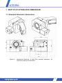
1
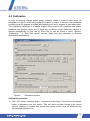
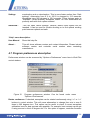
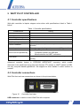
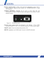
WATT PILOT Motorized Attenuator USER MANUAL Rev 3 November 2013 WATT PILOT November 2013 Copyright Altechna Ltd. All Rights Reserved No part of this manual, including the products and software described in it, may be reproduced, transmitted, transcribed, stored in a retrieval system, or translated into any language in any form or by any means, except documentation kept by the purchaser for backup purpose, without the express written permission of Altechna Ltd. (“ALTECHNA”). Product warranty or service will not be extended if: 1 The product is repaired, modified or altered. Unless such repair, modification of alteration is authorized in writing by ALTECHNA; OR 2 The serial number of the product is defaced or missing. ALTECHNA PROVIDES THIS MANUAL “AS IS“ WITHOUT WARRANTY OF ANY KIND, EITHER EXPRESS OR IMPLIED, INCLUDING BUT NOT LIMITED TO THE IMPLIED WARRANTIES OR CONDITIONS OF MERCHANTABILITY FOR A PARTICULAR PURPOSE. IN NO EVENT SHALL ALTECHNA, ITS DIRECTORS, EMPLOYEES OR AGENTS BE LIABLE FOR ANY INDIRECT, SPECIAL INCIDENTAL, OR COSEQUENTIAL DAMAGES (INCLUDING DAMAGES FOR LOSS OF PROFITS, LOSS OF BUSINESS, LOSS OF USE OR DATA, INTERUPTION OF BUSINES AND THE LIKE), EVEN IF ALTECHNA HAS BEEN ADVISED OF THE POSSIBILITY OF SUCH DAMAGES ARISING FROM ANY DEFECT OR ERROR IN THIS MANUAL OR PRODUCT. SPECIFICATIONS AND INFORMATION CONTAINED IN THIS MANUAL ARE FURNISHED FOR INFORMATIONAL USE ONLY, AND ARE SUBJECT TO CHANGE AT ANY TIME WITHOUT NOTICE, AND SHOULD NOT BE CONSTRUED AS A COMMITMENT BY ALTECHNA. ALTECHNA ASSUMES NO RESPONSIBILITY OR LIABILITY FOR ANY ERRORS OR INACCURACIES THAT MAY APPEAR IN THIS MANUAL, INCLUDING THE PRODUCTS AND SOFTWARE DESCRIBED IN IT. THIS MANUAL IS DIRECTLY CONNECTED TO FIRMWARE VERSION. LATEST FIRMWARE, SOFTWARE AND MANUAL VERSIONS CAN BE DOWNLOADED FROM www.altechna.com. Products and corporate names appearing in this manual may or may not be registered trademarks or copyrights of their respective companies, and are used only for identification or explanation and to the owner’s benefit, without intent to infringe. 2 THIS PAGE INITIALLY LEFT BLANK 3 CONTENTS 1 INTRODUCTION .......................................................................................................... 6 1.1 1.2 1.3 1.4 1.5 Watt Pilot short description .................................................................................... 6 General safety requirements ................................................................................. 6 Symbols ................................................................................................................. 6 Regulation ............................................................................................................. 7 Operating and storage conditions .......................................................................... 7 2 OPERATION PRINCIPLE ............................................................................................ 9 3 WATT PILOT MAIN COMPONENTS ......................................................................... 10 3.1 4 5 WATT PILOT SOFTWARE DESCRIPTION ............................................................... 12 4.1 4.2 4.3 4.4 4.5 4.6 Computer requirements ....................................................................................... 12 Software installation ............................................................................................ 12 Program first run .................................................................................................. 17 Watt Pilot “Selector” window ................................................................................ 18 Calibration ........................................................................................................... 20 Watt Pilot “Control” window ................................................................................. 22 4.7 4.8 4.9 Program preferences description......................................................................... 26 Motor settings description .................................................................................... 28 Firmware update.................................................................................................. 30 WATT PILOT CONTROLLER .................................................................................... 31 5.1 5.2 6 7 Optics assembling ............................................................................................... 11 Controller specifications ...................................................................................... 31 Controller connections ......................................................................................... 31 WRITING SOFTWARE FOR WATT PILOT ............................................................... 33 6.1 6.2 List of supported operating systems for USB drivers ........................................... 33 Serial port parameters ......................................................................................... 33 6.3 6.4 6.5 6.6 6.7 Identifying serial port name ................................................................................. 33 Serial commands and protocol ............................................................................ 35 Software recommendations ................................................................................. 41 Serial command usage with National Instruments “LabView” .............................. 43 Relation between motor position and laser power ............................................... 43 WATT PILOT ATTENUATOR DIMENSIONS ............................................................ 45 4 7.1 7.2 7.3 8 TROUBLESHOOTING ............................................................................................... 49 8.1 8.2 8.3 9 Standard attenuator dimensions .......................................................................... 45 Big aperture attenuator dimensions ..................................................................... 46 Watt Pilot controller dimensions .......................................................................... 48 Real laser power does not match shown in software. .......................................... 49 “Upgrade controller firmware now?” message appears. ...................................... 49 Firmware upgrade was unsuccessful or interrupted ............................................ 52 LIST OF TABLES....................................................................................................... 53 NOTES .............................................................................................................................. 54 5 1 INTRODUCTION This user manual is designed to help to install and operate Watt Pilot. Before installing and operating Watt Pilot please read installation and operation instructions carefully. Safety instructions must be read carefully. If there are any questions about contents of this manual please contact [email protected]. Altechna reserves the right to update contents of this manual without any notification. 1.1 Watt Pilot short description Motorized Watt Pilot is a computer controlled laser beam attenuation device. It attenuates free space laser beam/pulse continuously without introducing additional energy fluctuations. Watt Pilot is controlled by computer via USB. 1.2 General safety requirements Motorized Watt Pilot is designed to operate in conjunction with laser system. All applicable rules and regulations for safe operation of lasers must be known and applied while installing and operating Watt Pilot. The customer is solely responsible for laser safety while using Watt Pilot as standalone device or integrated into system. The customer must consider protective measures. While assembling or operating Watt Pilot, do not stare at the direct or scattered laser light even with safety goggles. All parts of the body must be kept away from the laser radiation. While adjusting laser beam through Watt Pilot, laser power must be kept as low as possible. Hazardous laser radiation can increase while optical components or instruments are used in combination with Watt Pilot. Appropriate eye protection must be worn at all times. Electrical safety requirements must be complied while assembling and operating Watt Pilot. 1.3 Symbols WARNING! Sections marked with this symbol explain dangerous situations that can result as personal injury or death. Always read the associated information carefully, before performing indicated procedure. ATTENTION! Paragraphs preceded by this symbol explain hazards that could damage the instrument and connected equipment or may cause loss of data. 6 NOTE This manual also contains "NOTES" and "HINTS" written in this form. 1.4 Regulation ATTENTION! The following statement applies to the products covered in this manual, unless otherwise specified herein. The statement for other products will appear in the accompanying documentation. These limits are designed to provide reasonable protection against harmful interference in a residential installation. This equipment generates, uses, and can create radio frequency energy and, if not installed and used in accordance with the instructions, may cause harmful interference with radio communications. However, there is no guarantee that interference will not occur in a particular installation. If this equipment does cause harmful interference to radio or television reception, which can be determined by turning the equipment off and on, the user is encouraged to try to correct the interference by one or more of the following measures: Reorient or relocate the receiving antenna. Increase the separation between the equipment and receiver. Connect the equipment into an outlet on a circuit different from that to which the receiver is connected. Consult the dealer or an experienced radio/TV technician for help. ALTECHNA is not responsible for any radio television interference caused by modifications of this equipment or the substitution or attachment of connecting cables and equipment other than those specified by ALTECHNA. The correction of interference caused by unauthorized modification, substitution or attachment will be treated as responsibility of the user. ATTENTION! Cellular phones or other radio transmitters are not recommended to be used within the range of three meters of this unit since the electromagnetic field intensity may then exceed the maximum allowed disturbance values according to IEC 61326-1. 1.5 Operating and storage conditions For proper Watt Pilot functioning please use assigned controller (found in the same package). Using unassigned controller might be harmful to the device. 7 Environmental conditions that must be hold while storing, servicing and operating are: Storage temperature should be between -25 °C and +60 °C. Operating temperature is 25 °C ± 10 °C. Watt Pilot must be protected from humidity, dust and corrosive vapors to damaging optical components and electronics. Avoid strong static electricity and electromagnetic fields. avoid 8 2 OPERATION PRINCIPLE Figure 1. Watt Pilot operating principle. Color differences shows intensity of laser beam. Brighter red means more intensive laser beam. The motorized Watt Pilot incorporates 2 high performance Brewster type thin film polarizer’s, which reflect s-polarized light while transmitting p-polarized light. Rotating phase retardation of λ/2 wave plate is placed in the incident polarized laser beam. The intensity ratio of those two beams may be continuously varied without alteration of other beam parameters by rotating the waveplate. The intensity of either exit beam, or their intensity ratio, can be controlled over wide dynamic range. P-polarization should be selected for maximum transmission, or high purity s-polarization should be reflected when maximum attenuation of the transmitted beam takes place. Proper functioning of Watt Pilot requires optimal configuration of optical elements regarding to incident laser beam polarization contrast. Higher incident laser beam polarization contrast, leads to higher Watt Pilot output polarization contrast. 9 3 WATT PILOT MAIN COMPONENTS Optical components are placed into mechanical holders. Main mechanical components of motorized Watt Pilot are shown in Figure 2. Waveplate mount is designed to fit 1 inch diameter waveplate mount. Polarizer holder (Depends from optics) Waveplate mount Step motor Figure 2. Watt Pilot main components. Waveplate mount is attached to micro step motor. Waveplate is fixed using two mounting rings (see Figure 3). Waveplate inside the waveplate holder is rotating around the optical axis of incident laser beam. Step motor and waveplate mount are shipped together in one piece. Polarizer’s are placed into adapter for polarizer’s. Polarizer’s to the mount are fixed using 6 plastic bolts (3 for each polarizer). Adapter for polarizer’s and waveplate mount are fixed while using M4 screw. NOTE: Adapter for polarizer’s can vary from showed in picture depending from polarizer’s type (“Brewster” or “Broadband” thin film polarizer) and operational mode (reflection or transmission mode). Also big aperture attenuator option is available. Watt Pilot can be fixed to an optical table using posts and clamps or to the custom system while using M6 or M4 screw on the bottom and M4 screw on the side. See chapter “WATT PILOT ATTENUATOR DIMENSIONS” on page 45. 10 3.1 Optics assembling Figure 3. Assembling the Watt Pilot. NOTE Powder free gloves must be worn while mounting optical components. Avoid touching or scratching optical surfaces. STEP 1. Place polarizers into mechanical adapter. Polarizers must face each other with surfaces coated with dielectric coating. Dielectric coating is marked with an arrow, so you have to put the polarizer’s with the arrows on the sides facing each other. Then fix polarizer’s with the plastic bolts (use all 3 plastic bolts to fix one polarizer). NOTE Do not tighten up the bolts too much since it can bend the polarizer and thus distort the laser beam. STEP 2. Put the wave plate into attenuator between two mounting rings as shown. Be sure that wave plate is immobilized tightly. STEP 3. Attenuator consists of two mechanical parts. User should assemble both mechanical parts together. STEP 4. Use fixing screw to tighten both parts together. 11 4 WATT PILOT SOFTWARE DESCRIPTION 4.1 Computer requirements Free USB port. Watt Pilot is compatible with USB 1.1, USB 2.0 and USB 3.0 Computer administrator rights (only for installation) Windows XP sp3 (32-bit) Windows Server 2003 sp2 (32-bit) Windows Vista sp1 (32/64-bit) Windows Server 2008 (32/64-bit) Windows 7(32/64-bit) Windows 8(32/64-bit) Microsoft .Net framework 4.0 redistributable (installs automatically) 4.2 Software installation 1. Check for and download latest “Watt Pilot” software installer package from http://www.altechna.com/product_details.php?id=824. 2. Run downloaded “Watt Pilot-Setup.exe” installation file. In case you are installing on operating system that does not meet requirements, only USB drivers will be installed. Click "Yes" to continue. 12 3. Installation window will appear, click “Next” to continue: 4. Click “Next”: 13 5. Select installation directory and click “Next” to begin installation: 6. “Watt Pilot” software requires “Microsoft .NET Framework 4 Client Profile” or higher version to be installed. Setup will offer to download it, choose “Yes” if you have active internet connection. Choose “No” to download it from http://www.microsoft.com/enus/download/details.aspx?id=17113 and install it manually. You should choose “No” if you wish to install any newer version of framework, or do not have a working internet connection. This dialog will not appear if framework is already installed. Download size is 42 Mbytes. 14 7. Setup will download “Microsoft .NET Framework 4 Client Profile”. 8. After download is finished, “Microsoft .NET Framework 4 Client Profile” will be installed, wait for it to complete. This can take more than 10 minutes on slower machine. 15 9. Setup will finish by installing drivers. Click “Next” to continue: 10. Click “Finish” to end installation. Program cannot be opened if only drivers were installed (see step 2 for details). 16 11. “Watt Pilot” software icon will appear on “All Users” desktop and “All Users” start menu. 12. Connect waveplate rotator to Watt Pilot controller. 13. Connect Watt Pilot and PC via USB cable. 14. Plug in Watt Pilot power supply jack and AC adaptor to wall outlet. 15. Windows will detect new hardware. Wait until windows configures new device. 16. Device installation is now complete, launch “Watt Pilot” program using “Watt Pilot” icon on desktop. 4.3 Program first run Launch “Watt Pilot” program using “Watt Pilot” icon on desktop or from “Start Menu->All Programs->Altechna->Watt Pilot->Watt Pilot”. Watt Pilot “Selector” window will appear. At least one device must be displayed in the list. If the list is empty, please check USB cable, power connection and “ON/OFF” switch – it must be in “ON” position. Green LED near power switch must be active if power is OK. Click “File->Search For Devices” to refresh. For more information about Watt Pilot “Selector” window see section “ Watt Pilot “Selector” window” on page 18. Select Watt Pilot from a list and click “File->Connect”. Program will update controller firmware if necessary. Usually this process is automatic and does not require any action, just wait until “Firmware upgrade was successful!” message appears. If problems arise with firmware update, see “Firmware update” on page 30 and “TROUBLESHOOTING” on page 49. 17 Once connected to Watt Pilot, dialog will popup informing that no calibration file is found for new attenuator: Figure 4. Dialog box, shown if Watt Pilot calibration file is not found. Select “Yes”, calibration window will appear. Use instructions in section “Calibration” on page 20 to setup calibration. After calibration is done, “Watt Pilot control” window will appear. Use slider to select and set required power. See section “Watt Pilot “Control” window” window on page 22 if more information is needed. 4.4 Watt Pilot “Selector” window Watt Pilot “Selector” window contains a list of currently connected and powered attenuators. This window is used to choose device to work with if there are several controllers connected to single computer. Functions of this window are described in the picture below. Figure 5. Watt Pilot “Selector“ window. It is displayed every time program is started. There are three devices attached to PC in shown screenshot. Double click listed attenuator to open control window for it. Columns description: Name It is useful to give meaningful titles for each Watt Pilot, because they will be easily recognized if more than one is used in the same system. For example, name can be set to “1st Harmonic WP”, and another attenuator can be named as “2nd Harmonic WP”. New name is saved into controller internal memory, so it will be visible even if connected to another computer. Name length is restricted to 20 characters maximum. Watt Pilot can be renamed from “Watt Pilot control” window “Options->Watt Pilot Name...” menu option. 18 Serial Number This column shows unique Watt Pilot controller hardware serial number. It is used to identify hardware at low level. Use “Options->Watt Pilot Name...” menu option in control window to give meaningful name to attenuator. COM port Each Watt Pilot gets unique serial port name after first enumeration with computer. This column shows USB-serial port name assigned by Windows. COM port name is necessary to know for advanced users who want to use serial commands in their applications. See chapter “Serial commands and protocol” on page 35 for more details about this. Status This column shows “Connected” if attenuator control window is active otherwise it is blank. “File” menu description: Connect This opens control window for selected Watt Pilot, it does the same as double clicking in device list. If only one device is connected during program startup, control window will be opened automatically. See chapter “Watt Pilot “Control” window” on page 22 for information. Search For This will force searching for Watt Pilot devices attached to computer. It can help if not all devices are detected and listed automatically. Devices Close This will close Watt Pilot “Selector” window, but leaves control windows opened if any. Exit This will close Watt Pilot “Selector” window, and all control windows too. “Help” menu description: User Manual This will open this help file. About This will show software version and contact information. Please include software version and controller serial number when contacting manufacturer. 19 4.5 Calibration In order to correctly change output power, software needs to know at what angle λ/2 waveplate is. It can be fixed in any angle with respect to rotator. It is known, that waveplate is positioned at 45 degrees at highest attenuation point, and 0 degrees at zero attenuation. The purpose of calibration is to obtain angular offset between λ/2 waveplate and rotator hardware zero position, when one of these two conditions is met. Calibration window is opened automatically on first use of Watt Pilot, or can be found in menu “Options>Calibration…” in “Watt Pilot control” window. Make sure that attenuator is correctly aligned before calibrating. Figure 6. Calibration window. Calibration procedure: 1. Click “GO” button in section “Step 1” and wait till motor stops. This will drive waveplate holder to hardware zero limit switch. This will allow accurate homing from control window. Homing is needed after power loss during motion and will eliminate any accumulated position error. 20 2. Check checkbox in “Step 2” if using “Big aperture” waveplate rotator. See pictures below. Standard rotator. “Step 2” checkbox must be unchecked Figure 7. “Big aperture” rotator. “Step 2” checkbox must be checked Standard and "Big aperture" waveplate rotators. 3. Rotate waveplate by using buttons in section “Step 3”, and measure laser power after the attenuator. Number on the buttons represents motor moving distance (measured in stepper motor steps) and rotation direction. One step equals to 0.0115 degrees for standard waveplate rotator and 0.005 degrees for big aperture attenuator, using default settings. It is advisable to search for lowest power (max attenuation) position, because usually it can be spotted more easily and accurately. Power meter is not necessary for relative, coarse power attenuation, min power can be found using visualizer. 4. Select appropriate option in “Step 4” when minimum or maximum power is found. Angular offset is recalculated and shown in “Step 7” field every time “Step 4” selection is clicked. At this moment, main calibration goal is completed and “Apply” button can be clicked to apply changes. Further steps are optional, but can be set for convenience. 5. Calibration result can be verified using buttons in “Step 5” panel. Usage example: click “Drive to minimum power” button and wait till rotator stops. Use buttons “-10” and “10” (located in “Step 2”) to ensure if current position is really of lowest power. If it is, click “Apply”, else select “Minimum power” in “Step 4” again, to redefine offset. The same can be done with maximum power point. Checking both min and max positions in “Step 5” makes no sense. 6. Non-ideality of polarizers and waveplate will cause losses, so 100 % percent transmission will pass less energy than available, and 0 % transmission actually does not block all radiation. Real maximal and minimal transmitted power can be measured while calibrating Watt Pilot, in “Step 5”. These extreme values should be entered in relevant fields of “Step 6”. For example, one uses 1 W laser, and 20 mW is measured as minimal power, and 0.99 W as maximal power. So it is handy to check “Use absolute power measurement units”, put value “0.02” into field “Minimum measured value:”, “0.99” into “Maximum measured value:”, and write “W” into “Enter 21 measurement units to use:” textbox, because measurement units are “Watts”. 7. Click “OK” button to accept calibration or “Cancel” to discard. If dialog, asking to home will appear, answer “Yes” for correct device operation. 4.6 Watt Pilot “Control” window This window is used to change laser power after Watt Pilot attenuator. Calibration procedure must be finished before correct attenuator operation. Main components of this window are described below. 1. Watt Pilot name and serial number Output power level is always shown as percentage because it is directly related to waveplate angle Power also can be shown with absolute measurement units if correctly set in program preferences Upper indicator represents actual power level 3. Move lower slider to change required power level. Click “GO” button to apply it 10. This will drive waveplate to "Home" position, set by calibration process and preferences Figure 8. 2. “Power meter panel” Shows output power value, at which attenuator is currently set to 6. Preset buttons instantly change required power 4. Enter required power level here in percent. Click “GO” to set 5. Absolute required power field is used to set power level using known units if correctly set in program preferences 9. Hold this button 8. Immediately stops Watt to constantly Pilot rotation decrease power 7. Click “GO” to apply power level 9. Hold this button to which is shown in text boxes constantly increase power Watt Pilot “Control” window. Currently laser power is set to 5.05 mW or 50 % of full calibrated range. Measurement units are available because absolute minimal and maximal power values are set in program preferences during calibration process. Watt Pilot name and serial number is shown on each attenuator control window caption. Watt Pilot can be renamed by “Options-> Watt Pilot Name…” menu option. Name is convenient if more than one device is used in the same system. Name length can be up to 20 characters and is saved into controller memory. Serial number is unique for 22 each Watt Pilot controller and cannot be changed as it is used to identify hardware at low level. Please include serial number if contacting developers. Power meter panel always shows existing power after the attenuator. Percentage range is from 0 % to 100 % of transmission. Zero percent means that waveplate occurs at 45 degrees angle, beam polarization is rotated by 90 degrees and is maximally attenuated. Display reading “100 %” means that waveplate is rotated at minimum attenuation – maximum transmission angle. Figure 9. Power meter panel: Left - “Use absolute power measurement units” checkbox is set in “Options->Preferences”, right checkbox is unset. If “Use absolute power measurement units” checkbox is set in “Options-> Preferences” or during calibrating, numeric display, showing “mW” becomes active. Absolute power reading is converted from percentage value with respect to minimal and maximal measured power using power meter. Correct min and max power values must be set in program preferences or calibration windows. Lower slider changes power from 0 % to 100 % in 0.25 % steps. Values in lower numeric fields will alter according to slider position. There is a triangle-shaped marker above lower slider which shows power currently set in real-time – the same as “power meter panel” displays. Both options “Automatically execute “GO” after…” must be selected in “Options-> Preferences…” if power should be set immediately after slider move. Otherwise click “GO” button to actually set power. Enter required value (%) field is used to manually enter percentage of Watt Pilot transmission. Decimal point symbol is “.” (dot), two decimal places can be used. Valid range is 0.00 % .. 100.00 %. Option “Automatically execute “GO” after required power change” must be selected in “Options-> Preferences” if waveplate should rotate automatically after value of this field is changed. Otherwise click “GO” button to actually set power. Absolute required power field is available if “Use absolute power measurement units” option is set in “Options-> Preferences…” or “Options-> Calibration…”. Decimal point symbol is “.” (dot). Valid range is from “Minimum measured value” to “Maximum measured value” set in program preferences. Option “Automatically execute “GO” after required power change” must be selected in “Options-> Preferences” if waveplate 23 should rotate automatically after value of this field is changed. Otherwise click “GO” button to actually set power. Preset buttons can be used to quickly set predefined output power. Left click on any of them and appropriate value will appear in (4) or (5) text boxes. If Option “Automatically execute “GO” after required power change” is selected in “Options-> Preferences”, waveplate will rotate automatically, otherwise click “GO” button to actually set power. In order to edit preset values, right click on any preset button. “Edit Preset Buttons” window will appear: Figure 10. “Edit Preset Buttons” window. Currently preset values are 0%, 25%, 50%, 75%, 100% of transmission, because checkbox is unchecked. Otherwise all values would represent absolute power in user selected units. Option “Use absolute measurement units for preset buttons” will be enabled only if measurement units are correctly configured in “Options-> Preferences…”. If checkbox is set, clicking on preset button will update “Absolute required power field (5)”, else “Enter required value (%) field (4)” will be updated with value displayed on button. “GO” button. Click to set power (rotate waveplate). “STOP” button will cancel rotation. Buttons “<<” and “>>” will continuously decrease/increase power. Controller firmware must be up to date for these buttons to appear. These buttons are not available for controllers with serial numbers beginning with “4ATT”. If “Rotate continuous” option in program preferences is set, waveplate can be rotated to any angle, otherwise waveplate motion is restricted to 0..45 degrees. “Home” button will drive waveplate rotator to home limit switch and back to “Home position”, set in “Options-> Preferences…”. Usually this should be executed every time when device is turned on. 24 “File” menu description: Save Calibration… Current program settings can be saved to file. Configuration file includes all options in “Options-> Preferences”, preset values and calibration offset. Run time program configuration files are saved in folder “Application data for all users\Altechna\Watt Pilot\Settings”. Load Calibration… Program settings can be restored from file. Configuration file includes all options in “Options-> Preferences”, preset values and calibration offset. Current configuration will be overwritten. Show Device Selector This will open Watt Pilot “Selector” window. Close This Window This will disconnect from Watt Pilot and close active “Control” window. “Options” menu description: Calibration… This will open Watt Pilot calibration window. See chapter “Calibration” on page 20 for details. Preferences… This will open program configuration window. See chapter “Program preferences description” on page 26 for details. Watt Pilot Name… This will open “Rename Device” window. Use up to 20 characters for name. Enter new name and click “OK” to accept. Figure 11. “Rename Device” window. “Motor Settings” submenu description: Set Safe Settings This option will set waveplate rotator angular velocity to 8.73 deg/s, with acceleration and deceleration on. Such motor settings should be used if “Optimized settings” causes motor to stall or miss steps. Such problems may arise with old worn-out attenuators. Attenuation from 0 % to 100 % is changed in 7 seconds. These timings apply to “Standard” (small aperture) waveplate rotator. Set Optimized This will set waveplate rotator angular velocity to 14.076 deg/s, no 25 Settings acceleration and no deceleration. This is more faster motion than “Safe settings”. Attenuation from 0 % to 100 % is changed in 3.19 seconds. Waveplate turns 360 degrees in 25.6 seconds. These timings apply to “Standard” (small aperture) waveplate rotator. All new attenuators will perfectly work with such option selected. Advanced… “This will open “Motor settings” window, where motor speed can be tweaked. It can be used for trouble shooting or to find optimal working point between optimal and safe. “Help“ menu description: User Manual Show this help file. About… This will show software version and contact information. Please include software version and controller serial number when contacting manufacturer. 4.7 Program preferences description Preferences window can be accessed by “Options->Preferences” menu item in Watt Pilot control window. Figure 12. Program preferences window. Can be found under menu “Options->Preferences”. Rotate continuous. If checked, waveplate can be rotated continuously using “<<” or “>>” buttons in control window. This will cause attenuation to change from min to max 8 times in 360 degrees turn. This option can be useful to check if current waveplate calibration is set for best contrast ratio possible. For example, best contrast can be get if using second or third 45 degree slot. For this option to appear, controller firmware 26 must be updated to latest. This option is not available for controllers with serial numbers beginning with “4ATT”. “Home” position. Power can be set to max or min power after “Home” button clicked. Automatically execute "GO" after required power change. This allows waveplate to rotate automatically if required power was changed by editing values in numeric fields. Automatically execute "GO" after slider change. This allows waveplate to rotate automatically if required power was changed by moving the slider. “Automatically execute "GO" after required power change” must be checked for this options to be enabled. Use absolute power measurement units. Setting this will enable power to be measured with absolute measurement units. Minimum and maximum power values must be known for this option to work. This setting can also be changed in “Calibration” window. Measurement units to use. Alphanumerical string can be entered here to represent measurement units. Default is “mW”, but can be changed to “uW”, if working with “micro watts”. Minimal and Maximal power meter reading. These fields must be filled with minimal and maximal measured power values. Decimal separator symbol is dot (“.”). These values will appear as available power range in main window. Use absolute measurement units for preset buttons. If this is set, preset button values are shown as absolute power values, otherwise, preset button values mean % of transmitted power. Option "Use absolute power measurement units" must be set for this option to be enabled. Preset button values are recalculated automatically with respect to min and max measured power. 27 4.8 Motor settings description Motor settings can be accessed from “Watt Pilot Control window” by “Options-> Motor Settings-> Advanced…”. These settings are for advanced users only. Security passphrase for motor current controls is “I understand”. a) b) Figure 13. “Motor settings” window: a) Controller with latest firmware and serial number beginning with “5ATT” or “6ATT”; “Optimized” settings are applied. b) Controller with outdated firmware or serial number beginning “4ATT”; applied “Safe” settings. Passphrase “I understand” is entered in security field so motor current can be adjusted. Motor Enabled checkbox. If unchecked, no current flows through the motor windings. Default is checked. Resolution. Stepper motor can be driven in microstepping mode, so one motor step can be physically divided into 1 - no microstepping, 2 – half microstepping, 4, 8 or 16 microsteps. That means, that standard waveplate rotator can have resolution of 15600, 31200, 62400, 124800 or 2496000 steps per full turn. Big aperture waveplate holder can have 36000, 72000, 144000, 288000, 576000 steps per full turn resolution. No microstepping can cause motor resonance problems. The higher the resolution, the 28 smoother and quieter motor is, but motor torque and speed will decrease. Half stepping resolution is used as default. Step frequency. Motor step frequency, so waveplate angular velocity can be changed. Step frequency [Hz] can have discrete vales such as in range of 1 .. 64000. Waveplate angular velocity , where “ “ is integer [degrees/second] is equal to . Parameter “ ” is 15600 for standard attenuator, and 36000 for big aperture attenuator. Resolution divider “ ” can be 1, 2, 4, 8 or 16, as mentioned earlier in “Resolution” description. “Safe” step frequency is 759.4 Hz, “optimized” step frequency is 1224.2 Hz, but can be tweaked for best performance. Accelerate and Decelerate. If this option is set, motor gradually accelerates till maximum frequency is reached or decelerates till stop. This can help to solve stall problems on worn out mechanics, but causes motion to last longer. These options should be unchecked for normal usage. Default is unchecked. Overwrite Enable Input option is used in “Step-Dir” mode only. If checked, voltage level on "Enable" pins 3 and 11 in DB15 connector is ignored, and motor is enabled or disabled depending on selection to the right. Ask document “Watt Pilot User manual for advanced users” from supplier. Overwrite Dir Input option is used in “Step-Dir” mode only. If checked, voltage level on "Dir" pins 2 and 10 in DB15 connector is ignored, and motor direction is set depending on selection to the right. Ask document “Watt Pilot User manual for advanced users” from supplier. Motor current settings. Setting motor current higher than default can cause permanent damage to motor or controller, so current changing sliders are disabled by default. In order to activate them, please enter string “I understand” (without quotes) in security text field. Motion current is used when motor rotates waveplate, so it must be higher than standby current. Standby current is used when motor idles. Additional “STEP/DIR” current slider is present for controllers with serial numbers beginning with “4ATT” or newer controllers with outdated firmware version. This current drives motor continuously when controller operates in “Step-Dir” mode and motor is enabled by “Enable” signal on DB15 connector or by enable overwrite command. Motor current is cut off completely if enable signal is lost. In analogy with this, “Motion” and “Standby” current values are used for controllers with serial number “5ATT” or “6ATT”, so third slider is hidden. Third slider should be used only by advanced users and does not relate to watt pilot attenuator directly. Default motion current is 0.95 A for standard and big aperture attenuators, standby current is 0.3 A by default. Write settings button. Click this button to save configuration into controller memory. Currently displayed settings will be reloaded after controller power cycle. If this button is not used, previously saved changes will be loaded after controller restart. 29 Read settings button. This will load configuration from controller. 4.9 Firmware update Once connected, Watt Pilot software checks firmware version on device, and updates it if necessary. Progress bar will popup informing user that firmware update is in progress and one must wait until flashing process is finished. Figure 14. Normal firmware update process finish is indicated by “Firmware upgrade complete” message. It will take up to one minute and requires that user do not disturb update process. This process is not cancellable. Do not disconnect USB or power supply cables, do not shutdown the computer. This window can appear after “Watt Pilot” software is updated, because latest firmware comes with Watt Pilot installer file. Confirmation message will appear after update is completed, click “OK” and program will continue as usual. If firmware upgrade window is different than shown here, see “TROUBLESHOOTING” chapter on page 49. 30 5 WATT PILOT CONTROLLER 5.1 Controller specifications Watt pilot controller is bipolar stepper motor driver with specifications listed in Table 1 below. Table 1. Controller specifications. Characteristic Max output voltage Max output current Current regulation type Micro stepping capability Step frequency Position feedback Controller protection Device can be operated by Limit switch Rating +12 V 2A Pulse Width Modulation Full, Half, Quarter, Eight, Sixteen steps Up to 4 kHz Open loop operation (no external position feedback encoder) Driver have overheating and over current (2A) protection Step Dir pulses Computer software via USB port Microcontroller via UART connection One limit switch can be connected and used only for homing Advanced controller feature is “STEP/DIR INTERFACE” connector, which enable attenuator to be positioned using step and direction TTL pulses or UART instead of USB, not only computer based applications. Ask supplier for more details if custom solution is needed. 5.2 Controller connections Watt Pilot front and rear connectors are shown in the pictures below. Figure 15. Controller front view. USB connector is used to control Watt Pilot with computer. 31 Firmware upgrade button is hidden under small hole, highlighted by arrow. Used to recover if firmware upgrade process crashed. See “TROUBLESHOOTING” on page 52 if necessary. “STEP/DIR INTERFACE” connector can be used to control Watt Pilot with microcontroller via UART or “Step-Dir” pulses. Ask supplier for more details if custom solution is needed. Figure 16. Controller rear view. Controller power supply socket. Plug dimensions: outer diameter - 5.5 mm (GND), central pin diameter - 2.1 mm (+12 V). Watt Pilot requires +12 VDC/2 A power supply. “ON/OFF” switch. Green led indicates that controller is ON. “MOTOR” connector, 9 pin D-SUB female. Connect it to Watt Pilot attenuator. 32 6 WRITING SOFTWARE FOR WATT PILOT 6.1 List of supported operating systems for USB drivers In order to communicate with Watt Pilot, USB drivers are necessary. These are available for more operating systems than “Watt Pilot” software. Virtual USB-Com port drivers can be installed on Windows 2000 (32-bit), Windows XP (32bit), Windows Server 2003 (32-bit), Windows Vista (32/64-bit), Windows Server 2008 (32/64-bit), Windows 7 (32/64-bit), and Windows 8 (32/64-bit). There is no need to install any drivers on modern Unix-like (Linux, MAC) operating systems. Watt Pilot is automatically recognized and installed as “ttyUSB” device after connecting it to computer. You can check which serial port is assigned in your UNIX machine with command „root |dmesg | grep cp210x”. 6.2 Serial port parameters Serial port parameters to be used are shown in a table below. Table 2. Serial port parameters. Baud rate 38400 Parity None Handshaking None Stop bits 1 6.3 Identifying serial port name First step to control Watt Pilot using serial port and commands would be to find out which serial port is assigned for device. This can be seen in Watt Pilot “Selector” window list – see section “Watt Pilot “Selector” window” on page 18. In case only drivers were installed (no “Watt Pilot” software itself – see “Computer requirements” on page 12) serial port name could be checked in Windows “Computer manager”. Right click on “My Computer” (1), select “Manage” (2). “Computer manager” window will appear. Click on “Device Manager” under “Computer Management” tree (3) and look for “Ports (COM and LPT)” (4). Each connected and powered on attenuator appears as “Silicon Labs CP210x USB to UART Bridge (Serial port name)”. Serial port name is shown in parentheses, as seen in the picture below. 33 1 2 3 4 Figure 17. Finding Watt Pilot serial port name using Windows “Computer Manager”. Third way to identify Watt Pilot is to open each serial port and send “p” command. If attenuator is present on that port, it will send back string starting with “USB”, as listed in “Serial commands and protocol” on page 35. If device is not present, no bytes will be received or received string will not begin with “USB”. Serial port read timeout can be set to 50ms to speed up scanning process. This method is universal and can be used with any operating system. Read next chapters about serial port parameters and command list. Linux users can find Watt Pilot port by executing command “root |dmesg | grep cp210x”: 34 Figure 18. Finding Watt Pilot serial port under Linux. Screenshot is taken on Slackware Linux 13.37 32 bit OS. In the picture above we can see that one Watt Pilot (cp210x) device is assigned to “ttyUSB0” port. There is also shown installation command for “CuteCom” package, which is easy to use terminal application with GUI. 6.4 Serial commands and protocol Watt Pilot is a slave device according to computer and computer is a master device. That means that PC sends data requests to attenuator, and attenuator must respond. Watt Pilot itself will never send data to computer without request, except of two cases: if “Report zero position” command “zr” setting is set; also string “USB Mode\r\n” is sent upon controller start if controller starts in “Command” mode. Watt Pilot controller writes all received bytes to internal buffer. If it receives “carriage return” symbol (or ‘\r’ in C++ denotation, 13’th symbol in ASCII table, or 0x0D in hex), device will try to parse received bytes as a command string and will execute it. Attenuator echoes back every byte it receives back to computer except for ‘\r’. Symbol echoing is essential for users who literally type commands in terminal window. This enables user to see what data is sent to device, because not all terminal programs has a text field where sent symbols are shown. “\n” (0x0A) symbol is treated like all other symbols. 35 Watt Pilot will respond to byte ‘\r’ by sending additional data, if command requires it. Additional data is terminated with “\r\n” symbols. Termination symbols “\r\n” are essential for users who literally type commands in terminal window. These symbols are not visible, but they format “received data” window text so it looks organized. From computers perspective each command is ended by byte ‘\r’. “Enter” key press usually sends this symbol in most of terminal programs. Command and command parameter is separated by space symbol (0x20). For example, typing such string “g 3000” in terminal application and pressing enter key on the keyboard will drive waveplate rotator to absolute position of 3000 steps. Here “g” (0x67) is a command, space (0x20) is a separator, and “3000” (0x33, 0x30, 0x30, 0x30) is a command parameter, which corresponds to 3000 steps. All sent bytes in hexadecimal will be (0x67, 0x20, 0x33, 0x30, 0x30, 0x30, 0x0D), including command end symbol ‘\r’, or “Enter” key press. New command can be sent after 50 ms. There is no command acknowledge in protocol, so 50 ms delays between commands must be inserted. Otherwise command misinterpretation can occur. See table below for command list. Table 3. Serial commands list Command Description Move motor by x steps. mx Parameter x: Integer number. Can be positive (motor turns clockwise) and negative (motor turns counterclockwise). Place “-“ for negative notation. x can be in range of 2 147 483 646..+2 147 483 646. Example: “m 1000” to move 1000 steps clockwise and “m -1000” to move 1000 steps counterclockwise. Go to absolute coordinate. gx Parameter x: Integer number. Can be positive and negative. Place “-“ for negative notation. x can be in range of 2 147 483 646..+2 147 483 646. Example: “g -400” – motor turns while internal step counter reaches -400. Then send “m 1000” to move 1000 steps clockwise. Now motor stands in 600 position. ix Set coordinate counter to specific value. 36 Parameter x: Integer number. Can be positive and negative. Place “-“ for negative notation. x can be in range of 2 147 483 646..+2 147 483 646. Example: “i 625” – set coordinate to 625. Now send “so” to save position to controller. h Resets coordinate counter to 0. st Stop motor smoothly if it is currently running. This is preferred command to stop motor instead of “b”. b Brake movement immediately. This command stops motor, but step counter accuracy can degrade using watt pilot. zp Go to hardware zero position and reset step counter. Use this command to return waveplate to its home position, determined by zero position switch. Then motor stops controller stores 0 in coordinate counter and saves this value. Set motor micro stepping resolution. rx Parameter x: 1 Motor is driven in full steps mode. Waveplate holder turns once in 15600 steps for standard attenuator or 36000 for big aperture. 2 Half step mode. Waveplate holder turns once in 31200 steps. 4 Quarter step mode. Waveplate holder turns once in 62400 steps. 8 Eight step mode. Waveplate holder turns once in 124800 steps. 6 Sixteen step mode. Waveplate holder turns once in 249600 steps. Higher micro stepping levels demonstrate better position accuracy and no motor resonance. It is advisable to use half stepping operation mode. Set motor current then it is idles. This removes motor heat. Some amount of current must be left in order to keep position accuracy. ws x wm x Parameter x: Integer number in range of from 0 to 255. Motor current can be calculated using such equation: I = 0.00835x (A) Set motor current then it moves. Parameter x: Integer number in range of from 0 to 255. Motor current can be calculated using such equation: I = 0.00835x (A) Set acceleration. ax Parameter x: 37 Integer number in range of from 0 to 255. 1 is the lowest acceleration and 255 is the highest. 0 turns off acceleration. Turning on acceleration helps to increase position repeatability. Set deceleration. dx Parameter x: Integer number in range of from 0 to 255. 1 is the lowest deceleration and 255 is the highest. 0 turns off deceleration. Turning on deceleration helps to increase position repeatability. Set maximal motor speed. sx Parameter x: Integer number in range of from 1 to 65000, or 1 .. 64000 as accessed from Watt Pilot software. Watt Pilot waveplate rotation angular speed can be calculated using such formula: ; Here ω – angular waveplate rotation speed (degrees per second), r – micro stepping resolution – 1, 2, 4, 8 or 16. Controller advances motor per one step in time intervals equal to: µs Show controller settings, related to USB mode. Type this command only when using terminal and manual command entering. This is the way to see fundamental settings in “eye friendly” fashion. To get controller settings for software programming, use “pc” command instead. This command can be used to “ping” controller (to check if controller is attached to particular COM port). If device response to “p\r” string begins with “pUSB:“, it means that Watt Pilot is attached and is turned on. Return string (finished with 0x0A and 0x0D symbols): USB: [1] a=[2] d=[3] s=[4] wm=[5] ws=[6] wt=[7] r=[8] en:[9] zr:[10] zs:[11] p [1] Boolean 1 or 0. 1 if nothing is connected to 15 d-SUB connector. [2] Integer 0..255. Acceleration value; [3] Integer 0..255. Deceleration value; [4] Integer 1..65500. Speed value; [5] Integer 0..255. Motor motion current value; [6] Integer 0..255. Motor idle current value; [7] Integer 0..255. Reserved; [8] Integer 1, 2, 4, 8 or 6. Micro stepping resolution value (full, half, quarter, eight or sixteen); [9] Boolean 1 or 0. Motor enable: motor is enabled if 1 and motor is disconnected if 0; [10] Reserved; 38 [11] Reserved; Response example (default controller settings): USB: 1 a=232 d=232 s=59000 wm=114 ws=36 wt=114 r=2 en:1 zr:0 zs:0 Show all controller settings, separated by semicolon (;). Use this command when programming computer software to read all settings. Return string (finished with 0x0A and 0x0D symbols): pc [1];[2];[3];[4];[5];[6];[7];[8];[9];[10];[11];[12];[13];[14];[15];[16];[17];[18];[19];[2 0];[21];[22];[23];[24]; Character meaning: [1] Boolean 1 or 0. 1 if nothing is connected to 15 d-SUB connector. [2] Integer 0, 1, 2 or 3. Current motor run state: 0 – motor is stopped, 1 – accelerating, 2 – decelerating 3 – running at constant speed; [3] Integer from 0 to 255. Acceleration value; [4] Integer from 0 to 255. Deceleration value; [5] Integer from 1 to 65500. Speed value; [6] Integer from 0 to 255. Motor motion current value. I = 0.00835x (A); [7] Integer from 0 to 255. Motor idle current value. I = 0.00835x (A); [8] Integer from 0 to 255. Reserved; [9] Integer 1, 2, 4, 8 or 6. Micro stepping resolution value (full, half, quarter, eight or sixteen); [10] Boolean 1 or 0. Motor enable: motor is enabled if 1 and motor is disconnected if 0; [11] Reserved; [12] Reserved; [13] Reserved; [14] Reserved; [15] Reserved; [16] Reserved; [17] Reserved; [18] Reserved; [19] Reserved; [20] Reserved; [21] Reserved; [22] Reserved; [23] Reserved; [24] Reserved. Response example (default controller settings): 1;0;232;232;59000;114;36;114;2;1;1;0;0;0;1;0;1;1;1;0;0;0;0;1; Return running state of the motor and current position. o Return string (finished with 0x0A and 0x0D symbols): [1];[2] 39 [1] Integer 0, 1, 2 or 3. Current motor run state: 0 – motor is stopped, 1 – accelerating, 2 – decelerating 3 – running at constant speed; [2] Integer in range of -2147483646..+2147483646. Current motor position; Response example: 3;4437 Use this command to determine if motor has done its movement. After issuing any move command, poll “o” command in time intervals about 250 ms and decode response. If [1] parameter become 0, it means that motor has stopped and is ready for next move command. Motor enable. en x j Parameter x: 1 Motor is enabled. 0 Motor is disconnected. Reset controller. Controller resets in 4 s after issuing this command. It is equivalent to power cycle. This command can also enter into firmware upgrade mode if firmware upgrade button is pressed. All changed settings and position are restored in previous state, if “ss” and/or “so” commands was not issued before reset. Then controller starts, it sends string “USB mode” if nothing is connected to 15 pin D-SUB connector in front. a0 Turn off acceleration. d0 Turn off deceleration. ss Save settings of controller. Save configuration mentioned in “pc” command description to controller memory. Configuration saved by “ss” command will be restored on controller power on. Write 20 character long name to controller sn x n Parameter x: 20 characters. If x is not 20 symbols, then returned name can consist of unreadable characters. Please space pad trailing name. Show name. Returns 20 character string, saved by “sn” command. Return: 20 character string 40 6.5 Software recommendations There are plenty of applications built for serial port communication. Windows XP (and full installations of Windows 7 or Windows 8) has native “hypertrm.exe” terminal application, which can be launched by typing “hepertrm” in “Run” dialog (Win key + R). Linux and OS X users can use free “CuteCom” (http://cutecom.sourceforge.net) utility, see Figure 18 on page 35. For Windows OS it is recommended to use free tool “terminal.exe” from https://sites.google.com/site/terminalbpp Figure 19 (p 42). Configure “terminal.exe” as follows: 1. Select correct com port number (see “Identifying serial port name” on page 33); 2. Select correct serial port configuration values (see Table 2 on page 33); 3. Set “Hex” checkbox if received characters should also be shown as hexadecimal values; 4. Click “Connect” button; 5. Type in command and press “Enter” key on keyboard. Command string “p\r” is sent to device as shown in example picture. Look at “Serial commands and protocol” on page 35 for available commands; 6. Watt Pilot response is shown in middle pane. Hex representation of all received bytes is shown on the right. Controller “speed” setting is set to “55000” as seen in example screenshot. 41 1 2 4 3 6 5 Figure 19. “terminal.exe” window with “p” command sent. Presets can be configured for frequently used commands. Click “Set Macros” button, “Macro Settings” window will appear. Figure 20. Command string presets can be configured by clicking “Set Macros” button in main “terminal.exe” window. Type in string which should be sent, and name of this preset. Hexadecimal values can be entered with “$” prefix. For example command end symbol “\r” [0x0D] should be entered as “$0D”. “Stop” command definition is shown in example. Click “Save” button to save your presets. “Stop” button will appear in “Macros pane” of main window. Press it to stop 42 attenuator motor motion. 6.6 Serial command usage with National Instruments “LabView” There is a „Serial port“ control in LabView. Add it to your LabView project and set its properties to parameters listed in “Table 2” on page 33. Then use commands described in “Serial commands and protocol” (p 35) to control motor: use „g xx“, „m xx“ commands for moving, and „o“ command for checking if motor has stopped. To calculate motor step position for required laser power, use formulas, shown in in chapter “Relation between motor position and laser power” on page 43. 6.7 Relation between motor position and laser power Transmitted laser power ratio can be in range of 0.0 (max attenuation) to 1.0 (min attenuation). According to Malus' law, waveplate angle φ can be calculated from “ratio”: φ (√ ) (degrees). In order to get motor step position “steps” from waveplate rotator angle φ, use relation , where coefficient “k” is “steps per unit”, depending on waveplate rotator. k = 43.333 steps/deg for standard attenuator, and k = 100.0 for big aperture attenuator; coefficient “r” is controller’s resolution parameter, it must be read from controller using “p” command”, or got in “Watt Pilot” software “Options>Motor Settings->Advanced…”. “r” can be 1, 2 (default), 4, 8, 16 (microsteps per step). So motor step position “steps”, using standard attenuator with default (unchanged from purchase) settings, can be calculated as: (√ ) where “ratio” is required transmission (0.0 .. 1.0), “43.333” is “step per degree” for standard attenuator, and “2” is default resolution multiplier. Usually arccosine function (acos()), found in programming packages operates with radians, so degrees must be converted to radians. Real relation between “ratio” and “steps”, used in “Watt Pilot” software is calculated using following C# methods: // Returns step position to be passed to “g steps” command. // ratio – double in range 0.0 to 1.0. public Int32 GetStepPositionFromRatio(double ratio) { return GetStepPositionFromDegrees(GetAngleFromRatio(ratio)); } // stepsPerUnit: 43.333 for standard attenuator or 100.0d for Big aperture attenuator. // resolution: 1.0d, 2.0d, 4.0d, 8.0d, 16.0d, depending on controller settings. public Int32 GetStepPositionFromDegrees(double degrees) { 43 double steps = degrees * stepsPerUnit * resolution; return (Int32)steps; } // converts ratio (0.0..1.0) to waveplate angle in degrees. // ratio – double in range 0.0 to 1.0. public double GetAngleFromRatio(double ratio) { double angle = ((Math.Acos(Math.Sqrt(ratio))) * 180.0) / (2.0 * Math.PI); return angle; } Angular offset between waveplate and waveplate rotator is important, so “degrees” parameter in GetStepPositionFromDegrees(double degrees) should be adjusted accordingly to offset, before passing. 44 7 WATT PILOT ATTENUATOR DIMENSIONS 7.1 Standard attenuator dimensions Figure 21. Mechanical drawings of Watt Pilot standard attenuator. All dimensions shown in millimeters. 45 Figure 22. Mechanical drawings of Watt Pilot standard (continued). All dimensions shown in millimeters. attenuator 7.2 Big aperture attenuator dimensions Figure 23. Whole view of big aperture attenuator. 46 Figure 24. Mechanical drawings of Watt Pilot big aperture attenuator. All dimensions shown in millimeters. 47 7.3 Watt Pilot controller dimensions 94 mm 39 mm Figure 25. Watt Pilot controller dimensions. 48 8 TROUBLESHOOTING 8.1 Real laser power does not match shown in software. Click “Home” button in Watt Pilot “Control” window. This eliminates angular error, which can occur if power is lost during waveplate motion. 8.2 “Upgrade controller firmware now?” message appears. Sometimes Watt Pilot software will show dialog, asking whether to update firmware: Figure 26. Dialog, asking whether to update firmware. This will appear if controller firmware cannot be updated without user interaction and depends only on controller firmware version, not related to hardware revision. It will pop up if controller has firmware version prior to v8, released on August 22, 2012. These dialogs will newer show up again once firmware is updated. Warning! Upgrade process cannot be interrupted! Do not disconnect USB, attenuator or power supply cables, do not shutdown the computer. Do not use other devices while flashing. If upgrade is interrupted or unsuccessful, go to the end of this troubleshooter point to recover. Follow these steps to update firmware manually: 1. Answer “Yes” when asked about update dialog is shown in Figure 26. “Firmware Upgrade” window will appear. Click “Upgrade Firmware” button: 49 2. Progress bar on lower part of the window begins to fill, now program is waiting for user to press “Firmware upgrade” button, which is located inside controller box. Proceed to next step. 50 3. Press and hold firmware upgrade button located under small hole on controller’s front panel. This must be done in one minute, otherwise process must be restarted. Firmware upgrade button is marked by yellow arrow in the picture below. It can be accessed with teeth stick, for example. Figure 27. “Firmware upgrade” button location inside Watt Pilot controller. 4. Hold “Firmware upgrade” button pressed until confirmation about release will be displayed in “Firmware Upgrade” window as shown below. Usually button must be held pressed up to 15 seconds. Process status is displayed above progress bar. 5. Now wait till “Firmware upgrade was successful!” message appears. It will take up to 1 minute to complete. 6. Click “OK” in “Firmware upgrade complete” message box. “Firmware Upgrade” window 51 will close and “Watt Pilot control” window will start. 8.3 Firmware upgrade was unsuccessful or interrupted In case firmware upgrade ended unsuccessfully due to some reasons (cable disconnection, program crash…), usually such error will be thrown then trying to use Watt Pilot. Figure 28. Error, thrown if device firmware becomes corrupted. In order to recover, follow these steps: 1. Close “Watt Pilot” software; 2. Turn off controller using “ON/OFF” switch: 3. Press and hold down “Firmware upgrade” button located inside controller box, see Figure 27 on page 51 to find there it is; 4. Turn on controller, while holding firmware upgrade button pressed; 5. Release button after 10 second after power on; 6. Launch “Watt Pilot” software and try to use the device; 7. Firmware will be correctly rewritten automatically. Device will be ready to use after one minute. 52 9 LIST OF TABLES Table 1. Controller specifications. ...................................................................................... 31 Table 2. Serial port parameters. ........................................................................................ 33 Table 3. Serial commands list ............................................................................................ 36 53 NOTES 54 55 56