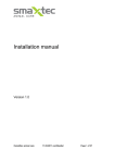
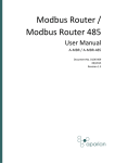
1
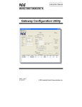
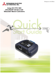
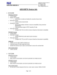
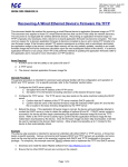
ICC
1600 Aspen Commons, Suite 210
Middleton, WI, USA 53562
Tel: (608) 831-1255
Fax: (608) 831-2045
Email: [email protected]
INDUSTRIAL CONTROL COMMUNICATIONS, INC.
Accessing Data on a Rockwell Automation Logix PLC
With the ETH-1000 Ethernet Gateway
The ICC ETH-1000 Multiprotocol Ethernet Gateway has the ability to act as a client to remote EtherNet/IPenabled devices, which include not only I/O or low-level slaves, but PLCs as well. There are two types of data
transfer mechanisms that exist within the EtherNet/IP protocol: TCP/IP-based “explicit" messaging, and UDP/IPbased "implicit" (or “I/O”) messaging.
EtherNet/IP explicit messaging is a point-to-point, request/response (client/server) protocol typically used for
unscheduled (on-demand) "information" messaging. On the other hand, implicit messaging is a multicast/unicast,
producer/consumer protocol designed for scheduled "control" data transfer. In ControlLogix parlance, I/O
messaging is the transfer of I/O data with an I/O device in the I/O configuration tree, or the transfer of Tag data via
a “Produced Tag” connection.
Legacy Rockwell Automation PLCs, such as the PLC5E and SLC5/05, only support a subset of explicit
messaging: data on these units can be accessed from the ETH-1000 by configuring an EtherNet/IP client “Typed
Read/Write” service object. Logix PLCs (such as the ControlLogix), however, support both explicit and implicit
mechanisms.
Retrieving data from a Logix PLC can be achieved by several methods. This document will explain three
methods for accessing data on a Logix PLC with provided examples. The first and simplest method directly
accesses the “Controller Tags” with explicit messaging data transfers. The second method maps “Controller
Tags” to File Numbers, and uses explicit messaging data transfers. The third method requires the use of a
Produced Tag connection on the PLC, and uses implicit messaging data transfers.
In places, this document shows some steps to take using Rockwell Automation software products (such as
RSLogix 5000). This is not intended to be a complete tutorial on using these products. It is assumed that the
reader has familiarity with the basic use of the controllers and software to program them. The information
presented here applies to all members of the ControlLogix family: CompactLogix, DriveLogix, SoftLogix and
FlexLogix, etc.
This document applies to ETH-1000 coprocessor firmware V2.320 and later. Older firmware must upgrade
to at least firmware version V2.320.
Method 1: Direct Tag Access
The ETH-1000 “Data Table Read/Write” service object is an explicit message that can be configured to directly
target “Controller Tags” with a data type of SINT, INT, and DINT. This method provides full read/write capability
from the ETH-1000 to the PLC memory.
In the following example, in the controller at slot 0, we will create a tag called “PLCInfo”, which is structured as an
array of 40 elements of data type INT. Note that in practice, this tag could be a standard tag or an alias tag. We
will then access the tag via a Data Table Read/Write explicit messaging command from the ETH-1000.
Example
1. In RSLogix 5000, create a new tag by right-clicking on the “Controller Tags” menu in the project tree and
selecting “New Tag…” (refer to Figure 1).
2. Define an array named “PLCInfo”, which is comprised of 40 elements of data type INT (refer to Figure 2).
Click “OK”.
08.07.2013 Rev. 4
Page 1 of 6
ICC
1600 Aspen Commons, Suite 210
Middleton, WI, USA 53562
Tel: (608) 831-1255
Fax: (608) 831-2045
Email: [email protected]
INDUSTRIAL CONTROL COMMUNICATIONS, INC.
Figure 1: New Tag Menu
3. The PLCInfo tag should now be visible in the
“Controller Tags” window (refer to Figure 3).
Figure 2: Create PLCInfo Array Tag
Figure 3: Viewing the PLCInfo Tag
4. The PLCinfo tag can now be accessed by configuring a “Data Table Read/Write” service object on the ETH1000 targeting the PLCInfo tag. The Slot field must be set to 0, to correspond with the location of the
controller in the Logix rack. The Element Data Type is set to 16-bit signed to correspond with the PLCInfo
data type of INT. The Element Type must match the size of the tag’s data type. If the tag’s data type is SINT,
then the Element Data Type must be set to 8-bit signed/unsigned. Likewise, if the tag’s data type is DINT, the
Element Data Type must be set to 32-bit signed/unsigned. Refer to the ETH-1000 User’s Manual for more
detailed information regarding configuration of EtherNet/IP connection objects and service objects.
08.07.2013 Rev. 4
Page 2 of 6
ICC
1600 Aspen Commons, Suite 210
Middleton, WI, USA 53562
Tel: (608) 831-1255
Fax: (608) 831-2045
Email: [email protected]
INDUSTRIAL CONTROL COMMUNICATIONS, INC.
Method 2: PLC/SLC Mapping
The PLC/SLC mapping method is achieved by mapping a Controller Tag to a File Number. Once this is
completed, an ETH-1000 “Typed Read/Write“ service object can be configured to target the File Number, and
hence access the associated Controller Tag. This method provides full read/write capability from the ETH-1000
to the PLC memory.
In the following example, in the controller at slot 0, we will create a tag called “SLCInfo”, which is structured as an
array of 40 elements of data type INT. Note that in practice, this tag could be a standard tag or an alias tag. We
will then expose the SLCInfo tag to the EtherNet/IP network by mapping it to File Number 10, which will provide
PLC/SLC-style direct access to the underlying tag via a Typed Read/Write explicit messaging command from the
ETH-1000.
Example
1. In RSLogix 5000, create a new tag by right-clicking on the “Controller Tags” menu in the project tree and
selecting “New Tag…” (refer to Figure 4).
2. Define an array named “SLCInfo”, which is comprised of 40 elements of data type INT (refer to Figure 5).
Click “OK”.
Figure 4: New Tag Menu
Figure 5: Create SLCInfo Array Tag
08.07.2013 Rev. 4
Page 3 of 6
ICC
1600 Aspen Commons, Suite 210
Middleton, WI, USA 53562
Tel: (608) 831-1255
Fax: (608) 831-2045
Email: [email protected]
INDUSTRIAL CONTROL COMMUNICATIONS, INC.
3. The SLCInfo tag should now be visible in the “Controller Tags” window (refer to Figure 6).
Figure 6: Viewing the SLCInfo Tag
4. Navigate to Logic…Map PLC/SLC Messages…
(refer to Figure 7). The “PLC2,3,5 / SLC Mapping”
window will appear.
5. In the first row under the “File Number” column,
enter a value of 10. On the same row, click on the
dropdown box in the “Tag Name” column and select
the SLCInfo tag (refer to Figure 8). Click “OK”.
6. The mapping is complete. The SLCinfo tag can now
be accessed by configuring a “Typed Read/Write”
service object on the ETH-1000 targeting File
Number 10. The Slot field must be set to 0, to
correspond with the location of the controller in the
Logix rack. The Element Data Type is set to 16-bit
signed to correspond with the PLCInfo data type of
INT. The Element Type must match the size of the
tag’s data type. If the tag’s data type is
DINT, then the Element Data Type must be
set to 32-bit signed/unsigned. Refer to the
ETH-1000 User’s Manual for detailed
information regarding configuration of
EtherNet/IP connection objects and service
objects.
Figure 7: Map Messages Menu
Figure 8: Mapping the SLCInfo Tag
08.07.2013 Rev. 4
Page 4 of 6
ICC
1600 Aspen Commons, Suite 210
Middleton, WI, USA 53562
Tel: (608) 831-1255
Fax: (608) 831-2045
Email: [email protected]
INDUSTRIAL CONTROL COMMUNICATIONS, INC.
Method 3: Produced Tag Connection
A Produced Tag connection allows another device (the ETH-1000, in this case) to make a direct connection to a
tag in the PLC’s database. Like standard implicit (I/O) data transfers, these connections are class 1 cyclic
multicast transfers. The main difference is that rather than connecting to a predetermined I/O assembly, any tag
in the PLC that the user designates as a Produced Tag can be accessed. The user must select the Produced
Tag option when creating the tag in RSLogix 5000. This designation makes the tag known to the PLC’s
Connection Manager as a potential connection target. Note that it is only possible to share controller-scoped
tags.
Produced Tag connections use unidirectional data flow (from the PLC to the ETH-1000), with a “heartbeat” in the
return direction. The ETH-1000 does not need to be present in the PLC’s I/O configuration, although this is
certainly allowed if required by the application, as the ETH-1000 is capable of simultaneously acting as both an
EtherNet/IP client and server.
Produced tags must have a data type that is cumulatively 4 bytes or larger. Therefore, single 8-bit (SINT) and 16bit (INT) tags cannot be configured as produced tags. Use DINT, REAL, or user-defined data types. Any userdefined data types must be at least 4 bytes or larger. An array of DINT, REAL, or user-defined data types are
also permitted. Produced tags must be less than 500 bytes in total size.
In the following example, in the controller at slot 0, we will create a Produced Tag in the ControlLogix PLC called
“ProducedTag”, which is structured as a single DINT (32-bit or 4-byte) data type.
Example
1. In RSLogix 5000, create a new tag by right-clicking on the “Controller Tags” menu in the project tree and
selecting “New Tag…” (refer to Figure 4).
2. The New Tag window will appear (refer to Figure 9). In the “Name” field, type “ProducedTag”. In the “Type”
dropdown box, select Produced. For “Data Type”, select DINT. Click on the “Connection…” button next to
the “Type” dropdown box: the Produced Tag Connection properties window as shown in Figure 10 will
appear. Depending on the PLC program, decide whether or not to check the “Send Data State Change Event
To Consumer(s)” checkbox according to the following criteria:
•
Check this box if the PLC program will use an IOT instruction to send updated tag values to the ETH1000. Note that if this box is checked, then the ETH-1000 will only be notified of changes to the produced
tag’s values when the IOT instruction executes.
•
Uncheck this box to automatically notify the ETH-1000 of changes to the produced tag’s values at the RPI
rate (no IOT instruction is necessary).
Click “OK” to close the Produced Tag Connection properties window, and then click “OK” again to close the
New Tag window.
08.07.2013 Rev. 4
Page 5 of 6
ICC
1600 Aspen Commons, Suite 210
Middleton, WI, USA 53562
Tel: (608) 831-1255
Fax: (608) 831-2045
Email: [email protected]
INDUSTRIAL CONTROL COMMUNICATIONS, INC.
Figure 10: Produced Tag Connection Properties
Figure 9: Create the Produced Tag
3. The tag is now ready to be accessed by the ETH-1000. You can now define the ETH-1000 EtherNet/IP client
connection object(s) and “Produced Tag” service object(s) to target the “ProducedTag” tag. The Slot field
must be set to 0, to correspond with the location of the controller in the Logix rack. The Consumed Bytes must
be set to the amount of data bytes contained in the produced tag, which in this example is 4 bytes as
determined by the DINT data type.
References
•
•
•
Establishing I/O Communications with RA ControlLogix Systems on EtherNet/IP (Rev 1.0) – Rockwell
Automation, March 10, 2003
Communicating with RA Products Using EtherNet/IP Explicit Messaging (Rev. 1.2) – Rockwell Automation,
June 7, 2001
ETH-1000 User’s Manual – Industrial Control Communications
08.07.2013 Rev. 4
Page 6 of 6