1
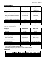
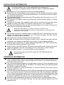
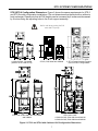
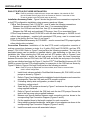
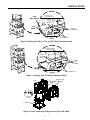
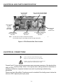
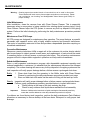
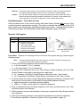
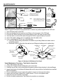
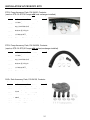
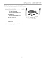
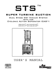
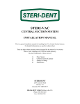
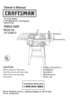
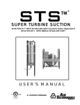
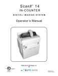
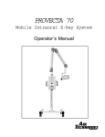
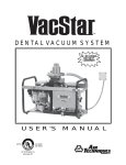
STS TM SUPER TURBINE SUCTION Dual Stage Dry Vacuum System with the Cyclonic Action Separator (CASTM) Heat Exchanger Installed TM STS-3 TM STS-6 TM STS-6 TM STS-3 with 4 Gallon CAS TM with 4 Gallon CAS TM with 8 Gallon CAS TM with 8 Gallon CAS TM P/N 54900 P/N 54910 P/N 54920 P/N 54930 No Heat Exchanger Installed STS-3 TM with 4 Gallon CASTM P/N 54900N STS-6 TM with 4 Gallon CAS TM P/N 54910N STS-6 TM with 8 Gallon CAS TM P/N 54920N with 8 Gallon CAS TM P/N 54930N TM STS-3 USER’S MANUAL TABLE OF CONTENTS Description Page Congratulations. . . . . . . . . . . . . . . . . . . . . . . . . . . . . . . . . . . . . . . . . . . . . . . . . . . . . . . .2 Warranty . . . . . . . . . . . . . . . . . . . . . . . . . . . . . . . . . . . . . . . . . . . . . . . . . . . . . . . . . . . . .3 On-Line Warranty Registration . . . . . . . . . . . . . . . . . . . . . . . . . . . . . . . . . . . . . . . . . . . .3 Safety Instructions . . . . . . . . . . . . . . . . . . . . . . . . . . . . . . . . . . . . . . . . . . . . . . . . . . . . .3 Sizing Guide . . . . . . . . . . . . . . . . . . . . . . . . . . . . . . . . . . . . . . . . . . . . . . . . . . . . . . . . . .4 Key Parts Identification . . . . . . . . . . . . . . . . . . . . . . . . . . . . . . . . . . . . . . . . . . . . . . . . . .4 Specifications . . . . . . . . . . . . . . . . . . . . . . . . . . . . . . . . . . . . . . . . . . . . . . . . . . . . . . . . .5 Site Requirements . . . . . . . . . . . . . . . . . . . . . . . . . . . . . . . . . . . . . . . . . . . . . . . . . . . .5 Product Specifications . . . . . . . . . . . . . . . . . . . . . . . . . . . . . . . . . . . . . . . . . . . . . . . . .5 Dimensions . . . . . . . . . . . . . . . . . . . . . . . . . . . . . . . . . . . . . . . . . . . . . . . . . . . . . . . . .5 Installation Information . . . . . . . . . . . . . . . . . . . . . . . . . . . . . . . . . . . . . . . . . . . . . . . . . .6 Operating Information . . . . . . . . . . . . . . . . . . . . . . . . . . . . . . . . . . . . . . . . . . . . . . . . . . .6 STS System Configurations . . . . . . . . . . . . . . . . . . . . . . . . . . . . . . . . . . . . . . . . . . . . . .7 Pipe Flow Schematic . . . . . . . . . . . . . . . . . . . . . . . . . . . . . . . . . . . . . . . . . . . . . . . . . . .8 Installation. . . . . . . . . . . . . . . . . . . . . . . . . . . . . . . . . . . . . . . . . . . . . . . . . . . . . . . . . . . .8 Single STS (STS-3) PVC Hose Installation. . . . . . . . . . . . . . . . . . . . . . . . . . . . . . . . .9 Dual STS (STS-6) Hose Installation . . . . . . . . . . . . . . . . . . . . . . . . . . . . . . . . . . . . . 10 Electrical Box Parts Identification . . . . . . . . . . . . . . . . . . . . . . . . . . . . . . . . . . . . . . . . . 12 Electrical Connections . . . . . . . . . . . . . . . . . . . . . . . . . . . . . . . . . . . . . . . . . . . . . . . . . 12 Maintenance . . . . . . . . . . . . . . . . . . . . . . . . . . . . . . . . . . . . . . . . . . . . . . . . . . . . . . . . . 14 Trouble Shooting. . . . . . . . . . . . . . . . . . . . . . . . . . . . . . . . . . . . . . . . . . . . . . . . . . . . . . 19 Accessories/Options . . . . . . . . . . . . . . . . . . . . . . . . . . . . . . . . . . . . . . . . . . . . . . . . . . . 19 Installation Accessory Kits . . . . . . . . . . . . . . . . . . . . . . . . . . . . . . . . . . . . . . . . . . . . . . 20 CONGRATULATIONS Congratulations on the purchase of your new STS™ Dual Stage Dry Vacuum System (Super Turbine Suction). The STS is a dry vacuum pump that produces high-volume air flow with multiple users online. The STS is a medical dry vacuum pump which is designed for use in a dental facility. The CAS ™ (Cyclonic Action Separator) tank will ensure that no liquids or foams enter the vacuum pump. The relief valve is easily accessible on the CAS. The patented vacuum relief valve maintains a constant uniform vacuum. The powerful permanent split capacitor motor, with a highly reliable contactor and powerful transformer can be depended upon to start every time. Your STS vacuum system and CAS separator tank are easily installed and maintained. This manual provides operation, installation, and maintenance instructions for the support of the STS Dual Stage Dry Vacuum System with or without a heat exchanger. Review and follow the guidelines included in this User Manual to ensure that the system provides the highest level of service. 2 WARRANTY The STS™ and CAS™ are warranted to be free from defects in material and workmanship from the date of installation for a period as follows Standard Warranty: 3 years (36 months) on complete unit. Extended Warranty: 2 years (24 months) all pumps, motors and housings. Total 5-year Warranty on all pumps, motors and housings. Any item returned to our factory through an authorized distributor, will be repaired or replaced at our option at no charge provided that our inspection shall indicate it to have been defective. Dealer labor, shipping and handling charges are not covered by this warranty. This warranty does not apply to damage due to shipping, misuse, careless handling or repairs by other than authorized service personnel. Warranty is void if equipment is installed or serviced by other than dealer service personnel authorized by Air Techniques. Air Techniques, Inc. is not liable for indirect or consequential damages or loss of any nature in connection with this equipment. This warranty is in lieu of all other warranties expressed or implied. No representative or person is authorized to assume for us any liability in connection with the sale of our equipment. ON-LINE WARRANTY REGISTRATION Quickly and easily register your new STS on-line. Just have your product model and serial numbers available. Then go to the Air Techniques web site, www.airtechniques.com, click the warranty registration link and complete the registration form. This on-line registration ensures a record for the warranty period and helps Air Techniques keep you informed of product updates and other valuable information. SAFETY INSTRUCTIONS Use of the STS not in conformance with the instructions specified in this manual may result in permanent failure of the unit. WARNING: To prevent fire or electrical shock, do not expose this appliance to rain in or moisture. All user serviceable items are described in the maintenance section. Manufacturing date code on serial number label is in the format Month YYYY. ATTENTION USERS: Alerts users to important Operating and Maintenance instructions. Read carefully to avoid any problems. Indicates type B equipment in accordance with IEC 601-1 Warns users of hot surfaces. There is a danger of burns. Work near these surfaces only after they have cooled down. Warns users that uninsulated voltage within the unit may be of sufficient magnitude to cause electric shock. Indicates the ON and OFF position for the Equipment power switch. I ON O OFF MEDICAL ELECTRICAL EQUIPMENT Indicates protective Earth Ground for the Equipment power switch. WITH RESPECT TO ELECTRICAL SHOCK, FIRE, MECHANICAL AND OTHER SPECIFIED HAZARDS ONLY IN ACCORDANCE WITH UL-60601-1, CAN/CSA C22.2 NO.601.1 66CA 3 SIZING GUIDE Choosing the correct size STS to meet practice depends on the number of air users and the anticipated air demand. To assure optimum operation, the demands should not exceed the number of air handpiece users shown below. Each chart lists the number of simultaneous High Volume Evacuators (HVEs) and Saliva Ejectors (SEs) that can be used in specific STS systems. STS-6 SYSTEM STS-3 SYSTEM (Two STS-3s Connected Together with 1 CAS) (with 1 CAS) HVE’s + SE’s HVE’s + SE’s 3 2 1 0 + + + + 0 2 4 6 6 5 4 3 2 1 0 + + + + + + + 0 2 4 6 8 10 12 KEY PARTS IDENTIFICATION CAS OUTLET TO PUMP VACUUM RELIEF VALVE SUCTION LINE FROM OPERATORIES SEPARATION TANK COVER WASH-OUT PORT AND VACUUM GAUGE 3 CAPTIVE KNOBS CASTM (Cyclonic Action Separator) SEPARATION TANK DRAIN WITH CHECK VALVE DRIP SHIELD COOLING SHROUD EXHAUST CONNECTION ELECTRICAL BOX HEAT EXCHANGER EXHAUST CONNECTION Detail of Exhaust Connection for Models without Heat Exchanger Installed 24V REMOTE WIRING ON/OFF SWITCH WITH CIRCUIT BREAKER LEVELING FEET 24V CONTROL CIRCUIT CURRENT PROTECTOR Figure 1. STS-3 with 4 Gallon CAS Main Parts Location 4 SPECIFICATIONS SITE REQUIREMENTS ELECTRICAL SINGLE (STS-3) DUAL (STS-6) Minimum Circuit Breaker Rating 20A 20A (Qty 2) Recommended or 40 A (Qty 1) Wire Size AWG Minimum Gauge #12 #12AWG (Qty 2) or #8AWG (Qty 1) NEMA 6-15 R NEMA 6-15 R (Qty 2) SINGLE (STS-3) DUAL (STS-6) 2-Inch Schedule 40 Pipe 3-Inch Schedule 40 Pipe 2-Inch Metal Pipe One 3-Inch or two 2-Inch Metal Pipe Receptacle PLUMBING Exhaust Vent Pipe with Heat Exchanger Exhaust Vent Pipe without Heat Exchanger (Note 1) Suction Line Riser Diameter ID 1/2 Inch Branch Line Diameter ID Minimum (Note 2) 1/2 Inch 1 Inch Main Line Diameter ID 1 Inch 1 Inch 1-1/2 or 2 Inch 1-1/2-Inch FNPT 1-1/2-Inch FNPT Drain Line 1-1/2-Inch Schedule 40 Pipe 1-1/2-Inch Schedule 40 Pipe Wash-Out Line 1/2-Inch FNPT Shut-off Valve 1/2-Inch FNPT Shut-off Valve End Fitting at STS NOTES: 1. Recommended pipe includes wrought iron pipe (black and galvanized) and copper pipe type M. 2. When installing more than one operatory on a Branch, use corresponding Main Line diameter pipe. PRODUCT SPECIFICATIONS ELECTRICAL SINGLE (STS-3) DUAL (STS-6) Voltage (Minimum/Maximum) 200/250 200/250 Full Load 13 Amps 26 Amps Starting Load 65 Amps 130 Amps Frequency 60 Hz 60 Hz Maximum Vacuum 14 InHg 14 InHg Preset Vacuum Level 10 InHg 10 InHg 27 SCFM 55 SCFM 4 or 8 Gallons plus adequate capacity for foam 4 or 8 Gallons plus adequate capacity for foam 304 Stainless Steel 304 Stainless Steel 40 to 104°F (10 to 40°C) 40 to 104°F (10 to 40°C) Maximum Exhaust Air Flow CAS™ SPECIFICATIONS Working Liquid Capacity Tank Material ENVIRONMENTAL CONDITIONS Operating Temperature Storage Temperature Relative Humidity Exhaust Fan Requirements 0 to 150°F (-18 to 66°C) 0 to 150°F (-18 to 66°C) 90% (no condensation) 90% (no condensation) 500 CFM Minimum 1000 CFM Minimum IEC601-1 CLASSIFICATION Class 1, Type B, Transportable, Continuous Operation Equipment not suitable for use in thr presence of flammable anaesthetic mixture(s). Protection against ingress of liquids -Ordinary DIMENSIONS SINGLE (STS-3) Weight Width Depth TM STS 110 Lbs. 20-1/2 in. 16-3/4 in. 4-Gallon CASTM 30 Lbs. 22-5/8 in. 18-3/4 in. 8-Gallon CASTM 40 Lbs. 22-5/8 in. 18-3/4 in. DUAL (Two STS-6 Pumps Stacked) Height Weight Width Depth Height 23-1/2 in. 220 Lbs. 20-1/2 in. 16-3/4 in. 46-1/2 in. 39-3/4 in 30 Lbs. 22-5/8 in. 18-3/4 in. 39-3/4 in 46 in. 40 Lbs. 22-5/8 in. 18-3/4 in. 46 in. 5 INSTALLATION INFORMATION Grounding reliability can only be achieved when the equipment is connected to a receptacle marked HOSPITAL ONLY or HOSPITAL GRADE. For new installations it is recommended to follow the following guidelines: Suction line from the operatories to be a minimum of 1-1/2” diameter and must be sloped (1/4” minimum for every 10’) toward the separation tank. The suction line should not have any sharp right angle bends. The suction line should be connected to the CAS separation tank with a short run of 1-1/2” diameter flexible tubing. STS systems can replace water ring pumps with smaller diameter piping in existing installations. The drain on the base of the separation tank must be connected to an open floor drain capable of handling 10 gallons in 30 seconds. Drain pipe size 1-1/2” schedule 40. The drain line should be a short run with a minimum slope of ¼” for every 10’ toward the drain (avoid any sharp right angle bends). 1. 2. Models with heat exchanger use schedule 40 pipe for connection to vent. Models with no heat exchanger use black pipe, galvanized pipe or copper pipe type M metal pipe for vent connection. The vent line should be 2” diameter pipe for a single STS and 3” diameter pipe for a dual system. The vent should be sloped 1/4” per 10’ towards the pump. Vent line must be capable of handling vapors and liquids. The outside vent must be protected from rain and animals. A flexible air exhaust hose is provided to connect to the 2” diameter vent pipe and heat exchanger. Hose clamps are provided to secure hose to heat exchanger and pipe. Wash-out water supplied via 1/2” copper tubing terminated with a 1/2” FNPT shut-off valve providing water pressure between 20 and 100 psi. Wash-out port on the CAS cover is a 3/8" push to connect elbow that connects to the water supply via supplied 10 foot 3/8” Poly tubing and 1/2" x 3/8" push to connect adapter. Refer to pages 9 through 11 for mounting and securing instructions. Any time the power to the STS is turned OFF the CAS tank will automatically drain. OPERATING INFORMATION The STS may be turned “ON/OFF” from a single, convenient location within the dental office using a Remote Control Panel. Remote wiring must be done by a licensed electrician in accordance with local codes. The vacuum level is factory preset at 10 in Hg (inches of mercury). This is the reading on the gauge when all HVE’s and SE’s are CLOSED. If this setting needs to be adjusted contact your dealer to readjust the setting. The unit is capable of running continuously. To conserve electricity, the system may be turned off when not in use. The CAS tank has been designed to collect the fluids evacuated during a normal operating day. If an excessive amount of fluids are collected in the CAS, the protective mechanism in the CAS will interrupt the vacuum flow in order for the tank to automatically drain. This process takes approximately 30 seconds. To restore the vacuum to full operation turn OFF the power to the STS for a minimum of 10 seconds and then turn back ON. Perform the daily maintenance procedures to Clean Vacuum Lines and Washout Tank. Turn the power OFF at the end of the day. This will drain collected liquids in the CAS separation tank. 6 STS SYSTEM CONFIGURATIONS STS-3/STS-6 Configuration Dimensions. Figure 2 shows the space requirements for STS-3 and STS-6 model configuration installations. The unit dimensions are identical with or without a heat exchanger. Please note that all CAS heights can be increased by 4 inches and decreased by 6 inches using the adjusting holes in the 4-rail support assembly. Always bolt or secure installation to the floor or wall when stacking the CAS onto dual STS pumps. 4 GALLON CAS, P/N 54800 (Used for STS-3 and STS-6) STS-3, P/Ns 54600 and 54600N STS-3 with 4 GALLON CAS, P/Ns 54900 and 54900N 2 STS-3 Pumps Stacked Together Used in STS-6 Configurations STS-6 and 1 CAS 4 GALLON CAS, P/Ns 54910 and 54910N 8 GALLON CAS, P/Ns 54920 and 54920N Figure 2. STS-3 and STS-6 with Stainless CAS Configuration Dimensions 7 PIPE FLOW SCHEMATIC Figure 3 shows the overall functional flow of STS systems with a CAS tank. Inlet and outlet connections to the tank is made at the top of the tank. This arrangement provides flexibility in installation, makes maintenance easier and adds to overall tank efficiency. Figure 3. STS with Stainless 8 Gallon CAS Functional Flow Diagram INSTALLATION Figure 4 shows the typical setup of a stacked STS system. SEE NOTES FOR EXHAUST CONNECT TO OUTSIDE VENT NOTES: 1. 2. MODELS WITH HEAT EXCHANGER USE SCHEDULE 40 PIPE FOR EXHAUST CONNECT TO OUTSIDE VENT. MODELS WITH NO HEAT EXCHANGER USE BLACK PIPE, GALVANIZED PIPE OR COPPER PIPE TYPE M METAL PIPE FOR EXHAUST CONNECT TO OUTSIDE VENT. Figure 4. Typical STS-3 with Stainless 4 Gallon CAS Stacked Completed Installation (Shown with heat exchanger installed) 8 INSTALLATION SINGLE STS (STS-3) PVC HOSE INSTALLATION. Note: Each kit provides the required hoses, clamps and adapters. No schedule 40 PVC pipe is included. Refer to page 18 for the contents of each kit. If more than 10 feet of hose is needed, order P/N 54118 (order by the foot) Installation Accessory Packs . Figure 5 shows the pipe and hose connections required for all STS configuration installations using accessory packs as follows:. CAS™ Tank Accessory Pack, P/N 54120 - used to make the following connections: Between the suction line and CAS tank. Item (1) on associated figure. Between the CAS tank and STS pump. Item (2) on associated figure. Between the CAS tank and drain line. Item (3) on associated figure. STSTM Pump Accessory Pack, P/N 54160 for unit with heat exchanger or 54160N for unit without heat exchanger - supplied with associated STS pump, used to connect each pump to the facility vent line, item (4) on figure 5. Connection Procedure. Installation of a single STS model configurations consist of making connections between a single 4 or 8 gallon CAS tank, P/N 54300, and a STS pump, P/N 54180. Refer to Figure 5 for the connection diagram and perform the following procedure. 1. Refer to Figure 2 and determine the installation footprint dimensions and connection requirements. Place the CAS tank and STS pump in position. 2. If installing side-by-side configuration, proceed to step 4. If stacking, perform step 3. 3. When stacking the CAS tank on top of a STS pump, refer to Figure 6 and secure the tank to pump using supplied hardware. Make sure to bolt or secure installation to the floor or wall when stacking any STS system. 4. Measure and record distance between each connection point. 5. Cut the supplied hose to the length required for each connection. 6. Using industry standard techniques, install pipe to hose adapters as shown in Pipe Connection Diagram Figure 5. 7. Install hoses and secure with associated clamps. LEGEND # Included in supplied accessory packs. * Not Included See Notes for exhaust connection requirements to outside vent REQUIRED CONNECTIONS (1) CAS tank suction input to facility suction line (2) CAS tank pump outlet to STS pump inlet (3) CAS tank drain to facility drain line (4) STS pump to the facility vent line NOTES: 1. Models with heat exchanger use schedule 40 pipe for exhaust connect to outside vent. 2. Models with no heat exchanger use black pipe for exhaust connect to outside vent. 3. The CAS tank can be located up to 25 feet from the STS Pump. Figure 5. STS Pump and CAS Tank Pipe Connection Diagram 9 INSTALLATION DUAL STS (STS-6) PVC HOSE INSTALLATION. Note: Each kit provides the required hoses, clamps and adapters. No schedule 40 PVC pipe is included. Refer to page 18 for the contents of each kit. If more than 10 feet of hose is needed, order P/N 54118 (order by the foot) Installation Accessory Packs . Figure 5 shows the pipe and hose connections required for a dual STS configuration installation using accessory packs as follows: CASTM Tank Accessory Pack, P/N 54120 - used to make the following connections: Between the suction line and CAS tank. Item (1) on associated figure. Between the CAS tank and drain line. Item (2) on associated figure. Between the CAS tank and combined STS pumps. Item (3) on associated figure. STSTM Pump Accessory Pack,P/N 54160 for unit with heat exchanger or 54160N for unit without heat exchanger - supplied with associated STS pump, used to connect each pump to the facility vent line, item (4) on figure 5. STSTM Dual Manifold Accessory Kit; P/N 54400 - used to connect two STS pumps together either side-by-side or stacked. Connection Procedure. Installation of the dual STS model configuration consists of making connections between a single 4 or 8 gallon CAS tank P/N 54300, and two STS pumps, P/N 54180. Refer to Figure 5 and perform the following procedure. The tank and associated pumps can be stacked or installed side-by- side depending on the size of the installation site. When stacking the CAS tank and two STS pumps, refer to Figures 6 and 7 showing the method to secure the tank and pumps. In any case, the hose connections between the suction line and CAS tank, the CAS tank and drain line and pump to the facility vent line are identical as shown by Figure 5. Use the STS™ Dual Manifold Accessory Kit; P/N 54400 to connect the two STS pumps together for connection to the CAS tank as shown by Figure 8. Refer to Figures 5 through 8 and perform the following procedure. Note: Each STS pump is shipped with an inlet manifold, which must be removed when used in a dual configuration. 1. 2. 3. 4. 5. 6. 7. 8. 9. Install check valves supplied in Dual Manifold Accessory Kit; P/N 54400, on both pumps as shown by Figure 8. Refer to Figure 2 and determine the installation footprint dimension and connection requirements. Place the CAS tank and STS pumps in position. If installing side-by-side configuration, proceed to step 6. If stacking, perform step 4. Stack the two STS pumps as shown by Figure 7 and secure the pumps together using supplied hardware. Refer to Figure 6 and stack the CAS tank onto the two STS pumps. Secure the tank to the top pump using supplied hardware. Measure and record distance between each connection point as shown in the corresponding Pipe Connection Diagram (Figures 5 and 8). Cut the supplied hose to the length required for each connection. Using industry standard techniques, install pipe to hose adapters as shown in the corresponding Pipe Connection Diagram (Figures 5 and 8). Install hoses and secure with associated clamps. 10 INSTALLATION 1/4-20 X 1-3/4 INCH HEX BOLT CAS DRIP SHIELD 1/4-INCH LOCK WASHER STS PUMP 1/4-INCH FLAT WASHER 1/4-20 HEX NUT Figure 6. Stacking the CAS on Top of a STS Pump Hardware Detail 1/4-20 X 2-3/4 INCH HEX BOLT 1/4-INCH LOCK WASHER 1/4-INCH FLAT WASHER 1/4-20 HEX NUT Figure 7. Stacking Two STS Pumps Hardware Detail HOSE Barbed Tee CHECK VALVE ASSEMBLY Check Valve Assembly 8 Gallon CAS Figure 8. Pump Combining Using Accessory Kit, P/N 54400 11 ELECTRICAL BOX PARTS IDENTIFICATION LOW VOLTAGE ENCLOSURE (See Note) DRY VACUUM TRANSFORMER 230VAC TO 24 VAC P/N 54623 LOW VOLTAGE 1/4 AMP CIRCUIT BREAKER P/N 117690 CAPACITOR CLAMP P/N 80178-4P 15 AMP ON/OFF CIRCUIT BREAKER P/N 54247 Note: 230VAC CONTACTOR P/N 55407 2.5” diameter. CAPACITOR 50 MFD 480 VAC P/N 54323 24 VAC wire for remote connections is located in own enclosure per UL Requirement. Run external wiring into low voltage enclosure through strain relief. Figure 9. STS-3 Electrical Box Parts Location ELECTRICAL CONNECTIONS Remove all power to the system prior to working within the electrical box.Contacting high voltage can cause serious injury or even death All systems must be wired directly from an electrical box that complies with local electrical codes Figures 9 and 10 show the parts identification and associated schematic of the electrical box used in STS-3 system pumps. Refer to the figures when making electrical connections or replacing a defective component isolated as a result of performing troubleshooting procedures. Please note that a Boost/Buck Transformer must be installed if the facility power is below the minimum 200V required prime input power. 12 Figure 10. Electrical Box Schematic for STS-3and STS-6 Models ELECTRICAL CONNECTIONS 13 MAINTENANCE Warning: Cleaning agents that contain bleach or foam should not to be used in this system. These cleaners will leech mercury from amalgam and pollute our environment. Please use non-foaming, non leeching, and biodegradable Clean Stream (pn# 57850) for proper cleaning. Initial Maintenance After installation, clean the vacuum lines with Clean Stream Cleaner. This is especially necessary when a new system is being installed into existing dental system piping. Using Clean Stream Cleaner helps the STS system to remove any built up deposits in the piping system. Perform the initial cleaning by performing the daily maintenance procedure provided below. Maintenance-Free STS Pumps All STS pumps are designed for maintenance-free operation. The pump features a powerful permanent split capacitor motor, with a highly reliable contactor and powerful transformer. The motor is completely water and oil-free and provides a dependable operation requiring no scheduled maintenance. Preventive Maintenance Whenever a service technician fulfills a repair call at the customer site routine checks should also be performed to detect general overall wear, and replacement of parts should be made if necessary before a failure causes a prolonged shut-down. This preventive maintenance program will aid in dependable equipment operation and help reduce breakdown. Scheduled Maintenance Since a well-organized maintenance program aids dependable equipment operation and reduces breakdown to a minimum, it is essential that the maintenance instructions be followed completely. The routine cleaning will remove any built up deposits in the piping system and the tank inspection will verify proper drainage before a failure causes a prolonged shut-down. Daily 1. 2. Yearly Clean drain lines from the operatory to the Buffer tanks with Clean Stream Cleaner by performing the daily maintenance procedure provided next page. Rinse out each tank with water via the wash-out fitting on the tank top cover Inspection will verify proper drainage before a failure causes a prolonged shut-down. Perform yearly maintenance procedure provided below to inspect tank interior. a. Check buildup at the base of the tank entering the drain. b. Check for any evidence that liquids have reached the float assembly. Important: Evidence of buildup at the base drain or liquids reaching the float assembly most likely means that a stricter adherence to the daily maintenance procedure is required. If problems are found during tank inspection, perform the daily maintenance Tank Washout procedure as necessary to remove buildup at the base drain. Reinspect to verify proper tank drainage. 14 MAINTENANCE Warning: The following steps must be performed while wearing skin and eye protection designed for handling typical Haz-Mat material. Use care at all times to prevent spillage. Caution: Use only Clean Stream Cleaner to maintain the system vacuum lines. Do not use chlorine bleach or solutions of sodium hypochlorite to disinfect the STS system. These materials may result in damage or destruction of equipment or loss of system performance. Daily Maintenance - Clean Vacuum Lines Clean all vacuum lines in the vacuum system with Clean Stream Cleaner daily as part of the overall preventive maintenance program. This helps to maintain the cleanliness of the CAS tank as well as the vacuum lines and tubing throughout the system. Using the 2.5 liter bottle of Clean Stream Cleaner, PN 57850 and the Clean Stream dispenser system, PN 57665. Required - Not Supplied Part No. Description 57850 2.5 Liter Bottle Clean Stream Cleaner (125 applications) 57665 Clean Stream Dispenser System 1 Bottle with o-rings and caps 1 Saliver Ejector Adapter 1 High-Volume Actuator Adapter 1 Small Suction Hose Adapter 1 Large Suction Hose Adapter Part No. 57850 Clean Stream Dispenser System, Part No. 57665 Procedure. Prepare the cleaning solution and clean the system daily by performing the following steps. Note: The Clean Stream Dispenser can hold a maximum of 2 liters of solution for cleaning up to 2 operatories. Mix solution quantity as necessary. 1. Fill the Clean Stream dispenser with tap water as applicable; a. to the line marked 1 L for 1 operatory b. to the line marked 2 L for 2 operatories 2. Using the 20ml measuring line in the Clean Stream Cleaner bottlecap, add the Clean Stream Cleaner concentrate to the dispenser as applicable; a. for 1 operatory, add 20ml of Clean Stream concentrate to the 1 liter of water b. for 2 operatories, add 40ml of Clean Stream concentrate to the 2 liters of water 3. As shown below, the interior of the Clean Stream dispenser bottlecap is configured with three holes for the insertion of HVEs and SEs via provided adapters as follows. a. attach saliva ejector to smallest atomizing adapter b. attach 1 or 2 high volume ejectors to respective adapter(s) 4. Refer to illustrations below and place dispenser in the 2-liter vertical position or the 1-liter horizontal position as necessary. 5. With the vacuum pump on and handpiece valves open, aspirate the Clean Stream solution from dispenser. 6. After each cleansing procedure, disconnect the handpieces and rinse the dispenser. 7. Record task completion on Operatory System Task Log provided on page 16. 15 MAINTENANCE PN 57644 High Volume Evacuator (HVE) PN ED598 2 Liter Dispenser Position Adapters PN 57644 and PN ED598 stay together once attached as shown. PN ED597 Note: PN ED597 Small Postion adapters into insertion hole connectors located on the dispenser bottlecap as shown. 1 Liter Dispenser Position Saliva Ejector Daily Maintenance Procedure - Tank Washout Refer to Figure 8 and perform the procedures to remove any solids trapped in the CAS tank. 1. Turn OFF the power to the STS. 2. Remove the plug from the wash-out port fitting on the top cover of the CAS tank. 3. Connect the 3/8-inch tubing from the water supply to the CAS wash-out port fitting. 4. Turn the water on and run the water through the CAS for approximately 2 minutes. 5. Turn off the water making sure to completely close the water valve. 6. Prior to restarting the STS do one of the following: a. Leave the 3/8-inch tubing connected to the wash-out port fitting. Make sure water valve is completely closed. b. Disconnect 3/8-inch tubing from the wash-out port fitting and making sure to replace plug. Wash-out Port Fitting Suction Line from Operatories Wash-out Port Fitting with Plug Inserted Wash-out Port Fitting Plug Removal Vacuum Relief Valve 3/8-inch Tubing Water Supply Connection Vacuum Connection Assembly Check Valve Captive Knob & Tank Clamp Vacuum Gauge Captive Knob & Tank Clamp CAS Outlet to Pump CAS Cover Captive Knob & Tank Clamp Figure 8. Stainless CAS Washout Port Detail Yearly Maintenance Procedure - Tank Interior Inspection 1. Turn off the power to the CAS. 2. Loosen the 3 captive knobs holding the cover to the tank. 3. Carefully remove the cover ensuring that the gasket remains firmly attached to the tank flange. 4. Inspect tank interior for buildup at the base drain and/or any evidence that liquids have reached the float assembly. 5. Prior to replacing the cover, inspect the gasket to ensure a clean smooth surface. 6. Install cover and finger tighten the 3 captive knobs. Do not over tighten knobs. 7. Verify all hoses are securely connected. 8. Perform the daily maintenance Tank Washout procedure as necessary. 16 Initial Date Date Initial Daily Clean Daily Clean Date Initial Daily Clean Date Initial Daily Clean Date Initial Daily Clean Date Initial Daily Clean Operatory System Clean Task Log Date Initial Daily Clean Date Initial Daily Clean Date Initial Daily Clean MAINTENANCE Note: Make copies of the maintained logs as necessary to insure availability to record completion of maintenance task. 17 MAINTENANCE Over or under adjustment of the Vacuum Relief Valve can degrade overall system operation. Adjustments should only be made to keep the suction level at the factory-set 10 InHg level, which is adequate to provide optimum operation. Vacuum Relief Valve Adjustment The STS system vacuum level is factory set at 10 InHg (inches of Mercury) as shown by the Vacuum Gauge. This suction level is more than adequate to provide a properly sized system service for a multiple-user dental facility. Whenever the suction level varies above or below the factory set point, adjustments can be made as necessary via the Vacuum Relief Valve. Refer to Figure 9 and adjust the system suction level by performing the following: 1. Access Vacuum Relief Valve by removing Vacuum Relief Valve Cap from the Vacuum Connection Assembly. 2. Hold Adjusting Nut with a 7/16-inch open-end wrench. 3. Using a flat screwdriver, adjust suction level as follows: a. Increase suction by turning adjusting screw clockwise in no more than 1/4 increments. b. Decrease suction by turning adjusting screw counterclockwise in no more than 1/4 increments. Vacuum Relief Valve Cleaning A dirty or clogged Vacuum Relief Valve degrades the STS system suction level. Clean the Vacuum Relief Valve by removing Vacuum Relief Valve Cap and carefully pulling the valve from the Vacuum Connection Assembly. Blow out accumulated solid deposits using clean low pressure compressed air. Vacuum Relief Valve Adjusting Screw Vacuum Connection Assembly 7/16-Inch Adjusting Nut Vacuum Relief Valve Cap Vacuum Relief Valve Cap CAS Cover 18 TROUBLESHOOTING PROBLEM POSSIBLE CAUSE POSSIBLE SOLUTIONS 1. No suction. a. Pump not turned on. a. Turn pump on.. b. Pump not running. b. Call your authorized Air Techniques dealer for repair service. c. CAS separator tank full. c. Shut unit “OFF” for 10 seconds then turn back “ON”. d. CAS hooked up backwards. d. Connect hose from STS to swivel tee fitting on CAS. e. Drain check valve clogged. e. Call your authorized Air Techniques dealer for repair service. f. Clogged drain. f. Call your local plumber. g. Kinked or collapsed suction hose. g. Check the suction line from the unit to the separation tank and the separation tank to the operatory line. If clogged, collapsed or kinked call your authorized Air Techniques dealer for repair service. h. Tank must be hooked up to an open drain. If hooked to an open drain and tank won't drain call your authorized Air Techniques dealer for repair service. h. Separator tank is full and will not drain. 2. Poor or low suction 3. Excessive suction a. Restricted air exhaust. a. Check air exhaust pipe to make sure it conforms to specifications. Check and clear possible restrictions in exhaust line. b. Restricted air suction. b. Check the suction line from the unit to the separation tank and the separation tank to the operatory line. If clogged , collapsed or kinked call your authorized Air Techniques dealer for repair service. a. Relief valve set high or stuck closed. a. Call your authorized Air Techniques dealer for repair service. b.Relief valve screen clogged. b. Call your authorized Air Techniques dealer for repair service. 4. Pump does not run. a. Site circuit breaker is “OFF”. a. Turn “ON” the site circuit breaker. b. Pump circuit breaker is “OFF”. b. Turn “ON” the pump circuit breaker. c. Low voltage circuit breaker is open. c. If the white section of the circuit breaker is visible, it is tripped. Flip this section back in to reset breaker. d. Low voltage remote switch turned “OFF”, or not connected properly. d. Make sure remote switch is turned “ON” or if not using remote, switch yellow and orange wires twisted together. e. Electrical problem. e. Call your authorized Air Techniques dealer for repair service. ACCESSORIES/OPTIONS Accessories/Equipment Options. The following lists the ordering number and description for accessory components available to maintain the STS product family. Contact an authorized Air Techniques’ dealer for information. Part No. 54400 54075 54061 56200 A1048 54199 54360 54514 Description Installation Kit, Dual System Kit, CAS Replacement Cover Kit, Washout Connector Vacuum Equalizer Guardian for existing CAS separation tank Kit, Remote Vacuum Relief Valve Assembly Pre-Installation Guide, STS and CAS (with Heat Exchanger Installed) Pre-Installation Guide, STS and CAS (No Heat Exchanger) 19 INSTALLATION ACCESSORY KITS STS™ Pump Accessory Pack; P/N 54160, Contents (used on STS-3 & STS-6 Pumps with heat exchanger installed) Part No. Component Description 57253 Quantity Barbed Adapter, 1-1/2-Inch MNPT by 1-1/2 Inch 2 1/4-Inch Diameter Hose, 17 Inch Long,1 Inch Wide Cuff 1 89324 Hose Clamp, 1-9/16- 2-1/2 Inch Maximum by 1/2 Inch 2 57234 1-1/2-Inch Street Elbow 1-1/2 Inches NPT 1.31 to 2.25-Inch Diameter Hose Clamp STS-3 and STS-6 User’s Manual 1 56057 57169 54430 1 1 1 STS™ Pump Accessory Pack; P/N 54160N, Contents (used on STS-3 & STS-6 Pumps with no heat exchanger installed) Part No. Component Description 57253 Quantity Barbed Adapter, 1-1/2-Inch MNPT by 1-1/2 Inch 2 1/4-Inch Diameter Hose, 36 Inch Long,1 Inch Wide Cuff 1 89324 Hose Clamp, 1-9/16- 2-1/2 Inch Maximum by 1/2 Inch 2 57234 1-1/2-Inch Street Elbow 1-1/2 Inches NPT 1.31 to 2.25-Inch Diameter Hose Clamp STS User’s Manual 1 54184 57169 54430 1 1 1 CAS™ Tank Accessory Pack; P/N 54120, Contents Part No. Component Description Quantity 54118 57169 57253 1-1/2 Diameter; Black/Grey PVC Hose 1.31 to 2.25-Inch Diameter Hose Clamp Barbed Adapter,1-1/2-Inch MNPT X 11/2 Inch 10 FT 5 4 57234 31453 1-1/2-Inch Street Elbow 1-1/2” NPT 1/4-20 X 1-3/4-Inch HEX Head Bolt, Grade 5 1 4 30610 30222 30049 1/4-Inch Plated Flat Washer 1/4-Inch Plated Split Lock Washer 1/4-20,Plated HEX Nut 8 4 4 20 INSTALLATION ACCESSORY KITS STS™ Dual Manifold Accessory Kit; P/N 54400, Contents Part No. Component Description 54129 Quantity Check Valve; 1-1/4 Inch to 1-1/2 Inch, Modified. Includes: Connector Adapter, 54234 PVC Pipe Length, 54291 Barbed P Connector Adapter, 57253 PVC Tee PCONN, 1-1/2 Inch FNPT All Sides: D. Includes: Barbed P Connector Adapter, 57253 PVC P Connector Adapter, 1-1/2 Inch MNPT X 1-1/2 Inch SPG 2 6 FT 5 4 30958 1-1/2 Diameter; Black/Grey PVC Hose Hose Clamp, 1.31 - 2.25 Inch Diameter. 1/4-20 X 2-3/4-Inch,HEX Head Bolt, Grade 5, Plated 1/4-Inch Flat Washer,18-8 ST 30920 1/4-Inch Split Lock Washer,18-8 ST 4 30049 1/4-20, Plated HEX Nut 4 54128 55222 54118 57169 31454 1 2 8 21 NOTES 22 NOTES 23 Air Techniques and ALLPRO Imaging are leading manufacturers of fine dental, medical and veterinary equipment from air and vacuum systems and X-ray film processors, to an impressive line of new products incorporating the most recent technological advances. These new products, vital components of the innovative professional practice, include intraoral cameras, digital imaging systems, which utilizes phosphor plate technology and, most recently, an intraoral digital X-ray system using sensor technology. Air Techniques and ALLPRO Imaging have been manufacturing quality products for the dental, medical and veterinary professional since 1962. Air Techniques and ALLPRO Imaging products are distributed only through authorized dealers. Refer to www.airtechniques.com or www.allproimaging.com to find a dealer in your area. AccentJ Intraoral Digital X-ray Image System Acclaim® Intraoral Digital Video Camera System Acclaim® USB Only Intraoral Digital Video Camera System AirStar® A/T 2000® XR GuardianJ Amalgam Collector 1-800-AIR-TECH Peri-Pro® (1-800-247-8324) www. Provecta 70J airtechniques.com Rinsendo Root Canal Disinfection System ScanX® STSJ VacStarJ 100 Plus 2010 Provecta V ScanX® 12 ScanX® DVM ScanX® NDT ScanX® 12 EV ScanX® 14 Portable ScanX® NDT Portable ScanX® 14 In-Counter STS and CAS are a registered trademark of Air Techniques, Inc. © Copyright 2005 Air Techniques, Inc. P/N 54430 Rev.J 1-800-AIR-TECH (1-800-247-8324) www.allproimaging.com