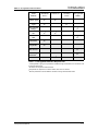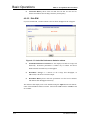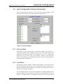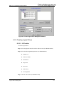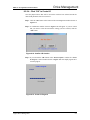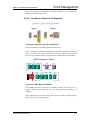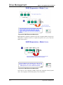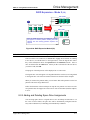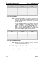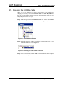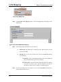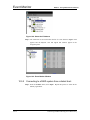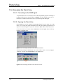
1
StorageWatch Java GUI Manager for RAID, Inc. Disk Array Controllers User’s Manual Revision 1.63 Software Revision: 1.51 or above RAID, Inc. StorageWatch: User’s Guide Overview Table of Contents Part 1: Getting Started With StorageWatch Chapter 1: Introduction ...................................................................................1-1 1.1 StorageWatch Overview................................................................................................................ 1-2 1.1.1 Product Description........................................................................................................ 1-2 1.1.2 Feature Summary............................................................................................................ 1-2 1.2 Featured Highlights..................................................................................................................... 1-4 1.2.1 Graphical User Interface................................................................................................ 1-4 1.2.2 Enclosure Management .................................................................................................. 1-4 1.2.3 Powerful Event Notification Function ............................................................................ 1-5 1.2.4 Java-based Remote Management.................................................................................... 1-5 1.2.5 Password Protection....................................................................................................... 1-5 1.3 Conceptual Foundation ............................................................................................................... 1-6 Chapter 2: Installation .....................................................................................2-1 2.1 System Requirements ................................................................................................................. 2-2 2.1.1 Server Running StorageWatch ....................................................................................... 2-2 2.1.2 Local client running StorageWatch Manager ................................................................. 2-2 2.2 RAID Chart................................................................................................................................. 2-3 2.3 Platform Requirements ............................................................................................................... 2-4 2.3.1 Platform Limitations ....................................................................................................... 2-4 2.3.2 Solaris Platforms ............................................................................................................ 2-4 2.3.3 Red Hat Linux Servers .................................................................................................... 2-6 2.3.4 Windows Platforms ......................................................................................................... 2-6 2.4 Software Setup............................................................................................................................ 2-8 2.4.1 Before You Start.............................................................................................................. 2-8 2.4.2 Installing StorageWatch.................................................................................................. 2-8 2.4.3 Installing Out-Band Components.................................................................................. 2-11 2.4.4 Installing In-Band Components .................................................................................... 2-14 2.4.5 Applet-Only Installation................................................................................................ 2-17 2.5 List of Filenames ...................................................................................................................... 2-20 2.6 Program Updates....................................................................................................................... 2-22 2.7 In-band SCSI ............................................................................................................................ 2-23 2.7.1 What is it and what is it used for?................................................................................. 2-23 2.7.2 How is it able to use the SCSI cable? ........................................................................... 2-23 2.7.3 Configuring a RAID Controller to Use In-band SCSI .................................................. 2-23 - iv RAID, Inc. StorageWatch: User’s Guide Overview Chapter 3:Configuration Options ...................................................................3-1 3.1 Accessing the Configuration Panel.............................................................................................. 3-2 3.1.1 Using Windows – StorageWatch Installed as In-Band.................................................... 3-2 3.1.2 Using Web Browser – StorageWatch Installed as Applet ............................................... 3-3 3.2 Primary Agent Configuration ...................................................................................................... 3-5 3.2.1 Base Settings ................................................................................................................... 3-5 3.2.2 Managed Secondary Agent Settings................................................................................ 3-7 3.3 Secondary Agent Settings............................................................................................................ 3-8 3.4 NPC Settings ............................................................................................................................... 3-9 3.4.1 Agent ............................................................................................................................... 3-9 3.4.2 Event Log ...................................................................................................................... 3-10 3.4.3 Fax Settings .................................................................................................................. 3-10 3.4.4 Pager Settings ............................................................................................................... 3-11 3.4.5 Email Settings ............................................................................................................... 3-13 3.4.6 SNMP Settings .............................................................................................................. 3-14 3.4.7 Broadcast Settings ........................................................................................................ 3-16 3.5 Rebooting the Controller ........................................................................................................... 3-18 Chapter 4: Basic Operations ........................................................................4-1 4.1 Starting StorageWatch Agents and NPC..................................................................................... 4-3 4.1.1 Under Windows (95/98/Me/NT/2000) OSes: .................................................................. 4-3 4.1.2 Under Unix or AIX OSes (Solaris 7 SPARC or x86, HP UX 11, or Red Hat Linux 6.1) 4-3 4.2 Starting StorageWatch Manager ................................................................................................. 4-4 4.2.1 Locally or via LAN under the Windows (95/98/Me/NT/2000) environment: .................. 4-4 4.2.2 For remote management via web browser (any supported OS)...................................... 4-4 4.2.3 Locally or via a LAN under a Unix or AIX workstation (Solaris 7 (SPARC, x86); Red Hat Linux 6.1) environment............................................................................................................. 4-5 4.3 Connecting and Disconnecting from a Disk Array ..................................................................... 4-6 4.3.1 Connecting to a RAID system ......................................................................................... 4-6 4.3.2 Disconnecting from a disk array system:........................................................................ 4-7 4.4 Setting Up Security................................................................................................................... 4-10 4.4.1 Setting a password for StorageWatch controller access ............................................... 4-10 4.4.2 Setting TCP Port Numbers............................................................................................ 4-11 4.5 Look and Feel ........................................................................................................................... 4-12 4.5.1 Look and feel overview ................................................................................................. 4-12 StorageWatch User's Guide -v- RAID, Inc. StorageWatch: User’s Guide Overview 4.5.2 Navigation Menus ......................................................................................................... 4-12 4.5.3 Tool Bar ........................................................................................................................ 4-12 4.5.4 Common Commands ..................................................................................................... 4-13 4.5.5 Menu Commands .......................................................................................................... 4-14 4.5.6 Windows Display Area.................................................................................................. 4-14 4.6 Using the RAID View Window................................................................................................ 4-16 4.6.1 Accessing the RAID View Display ................................................................................ 4-16 4.6.2 Using the Configuration View ...................................................................................... 4-17 4.6.3 Using the Logical View................................................................................................. 4-18 4.6.4 Using the Physical View ............................................................................................... 4-20 4.7 The Enclosure Window............................................................................................................. 4-26 4.7.1 Accessing the Enclosure Display .................................................................................. 4-26 4.7.2 Using the Enclosure Window........................................................................................ 4-26 4.8 The Event Log Window............................................................................................................ 4-28 4.8.1 Accessing the Event Log Display .................................................................................. 4-28 4.8.2 Using the Event Log to Monitor the System.................................................................. 4-28 4.9 The Statistics Window .............................................................................................................. 4-29 4.9.1 Accessing the Statistics Window ................................................................................... 4-29 4.9.2 Using the Statistics Window.......................................................................................... 4-29 4.10 Arranging Windows.................................................................................................................. 4-31 4.11 Exiting StorageWatch Manager ................................................................................................ 4-32 Part 2: Using StorageWatch for System Management Chapter 5: StorageWatch Considerations...................................................5-1 5.1 Background Information............................................................................................................. 5-2 5.2 Definition of Terms .................................................................................................................... 5-3 5.3 Operating With Spare Drives...................................................................................................... 5-4 5.4 Operating Without Spare Drives................................................................................................. 5-5 5.5 Before You Start ......................................................................................................................... 5-6 Chapter 6: Controller Configuration............................................................6-1 6.1 Accessing Controller Configuration Options.............................................................................. 6-2 6.2 Caching ....................................................................................................................................... 6-3 6.3 Host-Side .................................................................................................................................... 6-4 6.4 Drive-Side................................................................................................................................... 6-5 6.5 RAID .......................................................................................................................................... 6-6 - vi - StorageWatch User's Guide RAID, Inc. StorageWatch: User’s Guide Overview 6.6 Controller.................................................................................................................................... 6-7 6.7 Communication......................................................................................................................... 6-11 6.8 Redundant Controller................................................................................................................ 6-14 Chapter 7: Channel Configuration...............................................................7-1 7.1. Accessing Channel Configuration Options................................................................................. 7-2 7.2. User-Configurable Channel Parameters...................................................................................... 7-3 7.2.1. Channel Mode................................................................................................................. 7-3 7.2.2. Termination..................................................................................................................... 7-3 7.2.3. Default Xfer Clock (in MHz), Default Xfer Width........................................................... 7-4 7.2.4. ID pool / PID / SID ......................................................................................................... 7-4 7.3. Setting the configuration of a channel ........................................................................................ 7-5 7.4. Configuring New or Unassigned Drives..................................................................................... 7-8 Chapter 8: Drive Management......................................................................8-1 8.1. Scanning in Drives...................................................................................................................... 8-3 8.1.1 Scanning in a drive ......................................................................................................... 8-3 8.2. Logical Drive Management ........................................................................................................ 8-4 8.2.1 Accessing the “Create Logical Drive” Window ............................................................. 8-4 8.2.2 Creating Logical Drives ................................................................................................. 8-5 8.2.3 Expanding a Logical Drive........................................................................................... 8-10 8.2.4 Dynamic Logical Drive Expansion ............................................................................... 8-12 8.2.5 Adding and Deleting Spare Drive Assignments ............................................................ 8-15 8.2.6 Rebuilding Logical Drives ............................................................................................ 8-18 8.2.7 Deleting a LD............................................................................................................... 8-19 8.3. Creating and Deleting Logical Volumes................................................................................... 8-22 8.3.1 Accessing the “Create Logical Volume” Window ........................................................ 8-22 8.3.2 Creating Logical Volumes ............................................................................................ 8-23 8.3.3 To expand a logical volume .......................................................................................... 8-27 8.3.4 Delete a logical volume ................................................................................................ 8-29 8.4. Partitions ................................................................................................................................... 8-32 8.4.1 Overview ....................................................................................................................... 8-32 8.4.2 Partitioning a logical drive (LD) .................................................................................. 8-32 8.4.3 Partitioning a logical volume (LV) ............................................................................... 8-34 Chapter 9: LUN Mapping ..............................................................................9-1 StorageWatch User's Guide - vii - RAID, Inc. StorageWatch: User’s Guide Overview 9.1. Accessing the LUN Map Table................................................................................................... 9-2 9.2. LUN Mapping............................................................................................................................. 9-4 9.2.1. Mapping a Complete LD or LV....................................................................................... 9-4 9.2.2. Map a logical drive or volume partition to a host LUN.................................................. 9-6 9.2.3. Deleting a host LUN mapping ........................................................................................ 9-9 9.3. Extended LUN Mapping........................................................................................................... 9-11 9.3.1. Preliminaries ................................................................................................................ 9-11 9.3.2. Extended LUN Mapping ............................................................................................... 9-11 9.3.3. Adding a WWN Name ................................................................................................... 9-13 9.3.4. Deleting an Extended LUN Mapping or WWN Name................................................... 9-15 Part 3: System Monitoring Chapter 10: System Monitoring and Management .....................................10-1 10.1 SAF-TE / I2C / Fault Bus .......................................................................................................... 10-2 10.1.1 Accessing SAF-TE, I2C, or Fault Bus.......................................................................... 10-2 10.1.2 SAF-TE and I2C .......................................................................................................... 10-3 10.1.3 Fault Bus ..................................................................................................................... 10-4 10.2 S.E.S. Monitoring ..................................................................................................................... 10-5 10.2.1 Accessing S.E.S Monitoring ........................................................................................ 10-5 10.2.2 SES Management Device............................................................................................. 10-5 10.2.3 Managed Unit Status ................................................................................................... 10-6 10.2.4 Management Device Information ................................................................................ 10-7 10.3 Defining Enclosures.................................................................................................................. 10-9 10.3.1 Creating an enclosure ................................................................................................. 10-9 10.3.2 Removing a drive from an enclosure ......................................................................... 10-13 10.4 Displaying the Event Log ....................................................................................................... 10-14 10.5 Monitoring Statistics............................................................................................................... 10-15 Chapter 11: The Notification Processing Center........................................11-1 11.1.Before You Begin ..................................................................................................................... 11-2 11.1.1 About NPC................................................................................................................... 11-2 11.1.2 Platform Requirements................................................................................................ 11-2 11.2.Basic Running Requirements.................................................................................................... 11-3 11.3.Redundant NPC Modules ......................................................................................................... 11-4 11.4.Severity Levels ......................................................................................................................... 11-5 11.4.1 Level 1 Severity Events (examples).............................................................................. 11-5 11.4.2 Level 2 Severity Events (examples).............................................................................. 11-5 - viii - StorageWatch User's Guide RAID, Inc. StorageWatch: User’s Guide Overview 11.4.3 Level 3 Severity Events (example) ............................................................................... 11-6 11.5.Configuring Notification Options ............................................................................................. 11-7 11.5.1 Configuring Modem Settings ....................................................................................... 11-7 11.5.2 Configuring Fax Notification ...................................................................................... 11-7 11.6.Configuring Pager Notification............................................................................................... 11-12 11.7.Configuring Broadcast Message Notification......................................................................... 11-13 11.8.Configuring E-Mail Notification ............................................................................................ 11-14 11.9.Configuring SNMP Trap Notification .................................................................................... 11-15 Chapter 12: Event Monitor............................................................................12-1 12.1.Event Monitor Features ............................................................................................................ 12-3 12.1.1 Feature Summary ........................................................................................................ 12-3 12.1.2 Other Features ............................................................................................................ 12-3 12.2.Event Monitor Considerations .................................................................................................. 12-4 12.2.1 Note on Installation ..................................................................................................... 12-4 12.2.2 Before You Begin......................................................................................................... 12-4 12.2.3 Basic Running Requirements....................................................................................... 12-4 12.3.Starting Event Monitor ............................................................................................................. 12-5 12.3.1 Starting Agents and NPC............................................................................................. 12-5 12.3.2 Running the Program .................................................................................................. 12-5 12.4.Exiting Event Monitor ............................................................................................................ 12-10 12.4.1 Exiting from Event Monitor:...................................................................................... 12-10 12.4.2 Exiting from Event Monitor connected via web browser: ......................................... 12-10 12.5.Connecting and Disconnecting from a Disk Array ................................................................. 12-11 12.5.1 Connecting to a RAID system while working from the local Primary Agent host:.... 12-11 12.5.2 Connecting to a RAID system from a distant host:.................................................... 12-12 12.5.3 Disconnecting from a disk array system: .................................................................. 12-14 12.6.Using the Event Monitor......................................................................................................... 12-15 12.6.1 Display Controls........................................................................................................ 12-15 12.6.2 Basics ........................................................................................................................ 12-15 12.6.3 Using the Connection View ....................................................................................... 12-16 12.6.4 Using the Event List................................................................................................... 12-17 12.6.5 Event Severity Levels ................................................................................................. 12-19 StorageWatch User's Guide - ix - RAID, Inc. StorageWatch: User’s Guide Overview Chapter 13: Panel View.................................................................................13-1 13.1.About The Panel View.............................................................................................................. 13-2 13.1.1 Introduction ................................................................................................................. 13-2 13.1.2 Component Information............................................................................................... 13-3 13.1.3 Models with Panel Views............................................................................................. 13-3 13.2.Accessing the Panel View......................................................................................................... 13-4 13.2.1 Connecting to the RAID Agent .................................................................................... 13-4 13.2.2 Opening the Panel View .............................................................................................. 13-4 13.3.Panel View Messages ............................................................................................................... 13-5 13.3.1 Generating Message Tags ........................................................................................... 13-5 13.3.2 RAID Controller Information ...................................................................................... 13-5 13.3.3 IO Channel Message Tags........................................................................................... 13-6 13.3.4 RS-232C Serial Port/Ethernet Port Message Tag ....................................................... 13-6 13.3.5 Battery Backup Unit (BBU) Malfunction .................................................................... 13-7 13.3.6 PSU Status Message .................................................................................................... 13-7 13.3.7 Cooling FAN Module Status........................................................................................ 13-8 13.4.LED Representations ................................................................................................................ 13-9 Appendices ................................................................................................App-1 Appendix A. Command Summary ............................................................................................... App-2 A.1. Menu Commands ........................................................................................................App-2 A.2. Command Buttons.......................................................................................................App-3 Appendix B. Troubleshooting...................................................................................................... App-5 B.1. Common Oversights....................................................................................................App-5 B.2. Error Codes ................................................................................................................App-6 B.3. Error Messages...........................................................................................................App-7 Appendix C. Glossary ................................................................................................................ App-10 Appendix D. RAID Levels......................................................................................................... App-15 D.1. RAID Description .....................................................................................................App-15 D.2. Non-RAID Storage....................................................................................................App-15 D.3. RAID 0 ......................................................................................................................App-16 D.4. RAID 1 ......................................................................................................................App-16 D.5. RAID 1(0+1) .............................................................................................................App-17 D.6. RAID 3 ......................................................................................................................App-18 D.7. RAID 5 ......................................................................................................................App-18 -x- StorageWatch User's Guide RAID, Inc. StorageWatch: User’s Guide Overview Appendix E. Additional References........................................................................................... App-20 E.1. Java Runtime Environment .......................................................................................App-20 E.2. StorageWatch Update Downloads & Upgrading......................................................App-20 E.3. Uninstalling StorageWatch .......................................................................................App-20 StorageWatch User's Guide - xi - RAID, Inc. StorageWatch: User’s Guide Overview User’s Guide Overview Congratulations on your decision to use RAID, Inc.’s StorageWatch disk array management program. This management program allows you to control and monitor disk array systems, either from a local host, or from a remote station connected through a local area network (LAN) or the Internet. This guide discusses how to install and use StorageWatch to manage disk array systems incorporating RAID, Inc.’s SATA, SCSI-to-ATA, Fibre-to-ATA, SCSI-to-SCSI, Fibre-to-SCSI, or Fibre-to-Fibre controllers. An independent monitoring program, Event Monitor, is bundled with newer release of this manager (ver. 1.31 and above). The configuration and use of the program is discussed in Chapter 6. In addition to StorageWatch, you can also use the on-board RS-232 menu interface (non-PCI controllers only) or the text-based RAID Managers available for various operating systems to manage disk array systems incorporating RAID, Inc.’s disk array controllers. For information about these programs, see the documentation that comes with your hardware. - xii - StorageWatch User's Guide RAID, Inc. StorageWatch: User’s Guide Overview User Guide Structure and Chapter Overviews The StorageWatch User Guide is divided into three separate parts and Appendices Part 1: Getting Started With StorageWatch ♦ Chapter 1, Introduction. Provides information about StorageWatch, including a product description, a features summary and highlights, and section on basic concepts. ♦ Chapter 2, Installation Discusses how to install StorageWatch in your systems. Discussions include the system requirements, setting up hardware, software installation, and how to update your software by downloading updates from RAID, Inc.’s FTP site. ♦ Chapter 3, Configuration Options Describes how to configure the StorageWatch notification function for pagers, faxes, email, and broadcast. Information about the supported notification levels are also provided to aid in the explanation of these functions. ♦ Chapter 4, Basic Operations Discusses basic operations at system startup. These include starting StorageWatch, connecting and disconnecting from a disk array system, setting up system security, display controls, working with various disk array windows, and exiting from the program. Part 2: Using StorageWatch for System Management ♦ Chapter 5, StorageWatch Considerations Provides some background information on RAID and defines some terms that will be used throughout the rest of the manual. Discusses the use of spares and and how to replace a drive if no spares were in use. Finally provides a short discussion on StorageWatch preliminaries. ♦ Chapter 6, Controller Configuration Discusses how to access the controller configuration options and the different controller configuration options that are available. A detailed description of how to set these options is given and brief explanations of the different parameters given. ♦ Chapter 7, Channel Configuration Discusses how to access the channel configuration options and describes in detail the user configurable channel options that can be set. Discussions on setting the configuration of a channel and hot to confihire a new or unassigned drive are also discussed. StorageWatch User's Guide - xiii - RAID, Inc. StorageWatch: User’s Guide Overview ♦ Chapter 8, Drive Management This chapter describes the creation, expansion and deletion of both logical drives (LD) and logical volumes (LV). Different LD and LV options are explained and how to set the different options described in detail. A discussion on partitioning LDs and LVs can also be found in this chapter. ♦ Chapter 9, LUN Mapping Dicusses how to map complete or partitions of LDs and LVs to different LUNs. Detailed description of the mapping procedure is given. A discussion on how to delete LUN mappings is also given and a descritption of the LUN Mapping Table provided. Extended LUN mapping and all the associated options are also described in this chapter. Part 3: System Monitoring ♦ Chapter 10, Monitoring & Management Discusses how to use SAF-TE, I2C, Fault Bus and S.E.S monitoring devices to get updates on the component of storag system components. Descriptions of how to access these different monitoring devices is given and the type of information that is offered by these devices shown. This chapter also describes how to define enclosures to create a physical view of the storage system in StorageWatch and how to monitor the status of the drives in the physical view. ♦ Chapter 11, Notification Processing Center Describes the powerful Notification Processing Center (NPC) . Full descriptions of both platform and system requirements are provided and the use of redundant NPC modules discussed. Event severity levels are also introduced and defined. Configuration of the NPC is also discussed briefly. ♦ Chapter 12, Event Monitor This chapter introduces the event monitor and discusses the features, installation and how to start the event monitor. A description of how to use the event monitor and how to exit from the program is also described. ♦ Chapter 13, Panel View The Panel View customization is discussed fully in this chapter. Detailed instructions on how to access the panel view and how to use the panel view are given. Examples of status messages are shown and explanations of the status messages provided. Appendices ♦ Appendix A, Command Summary. Summarizes the available commands and command buttons in StorageWatch. - xiv - StorageWatch User's Guide RAID, Inc. StorageWatch: User’s Guide Overview ♦ Appendix B, Troubleshooting. Provides troubleshooting tips for some problems you may encounter while using StorageWatch. ♦ Appendix C, Glossary. Provides information and definitions of key technology terms used in this guide. ♦ Appendix D, RAID Levels. Provides information about the various RAID levels. StorageWatch User's Guide - xv - RAID, Inc. StorageWatch: User’s Guide Overview Usage Conventions Throughout this document, the following terminology usage rules apply: ♦ “Controller” always refers to Infotrend RAID array controllers; ♦ “StorageWatch” refers to the entire program and all of its modules. ♦ “StorageWatch Manager” refers only to the management interface, not to any of the other parts of the software. ♦ “Primary Agent” is the element of the software which permits one station to manage multiple RAID systems. The Primary Agent gets information from and sends commands to one or multiple Secondary Agents. ♦ “Secondary Agent” is the part of the software which allows the local RAID controller to talk to the Primary Agent (and thus to StorageWatch Manager). A Secondary Agent communicates with the RAID controller via SCSI bus or Fibre channel (using RAID, Inc. “In-band” technology), or even via an RS-232 serial port. Secondary Agents are the intermediaries between the Primary Agent and the RAID controllers. ♦ “NPC” and “Notification Processing Center” refer to the software subsystem that allows StorageWatch to notify system managers of events at any of the RAID systems being managed. ♦ "Event Monitor" is a software utility that runs separately from StorageWatch Manager. It requires agents to communicate between controller and management station. It also shares with StorageWatch Manager a part of Java class. Therefore, StorageWatch Manager should be installed even if the user prefers Event Monitor. Hardware and software requirments for installing the program is the same as those for StorageWatch. - xvi - StorageWatch User's Guide RAID, Inc. StorageWatch: User’s Guide Overview Revision History October 15, 2003 Chapter 13 and Chapter 14 have been merged into a single chapter, Chapter 13: Panel View. This chapter generically describes the panel view and removes the redundant descriptions that were previously in both Chapter 13 and Chapter 14. Part 4 of the previous edition has also been removed and the Chapter 13 has been included in Part 3 of the Manual 29 September, 2003 Figure 1-1 in Chapter 1 was changed to show a rackmount enclosure. Section 3-1 in chapter 3 was divided into two sections, the first being “Using Windows – StorageWatch Installed as InBand” and the second being “Using Web Browser – StorageWatch Installed as Applet” Section 3.5, “Rebooting the Controller” was also added. Modifications to table 14-1 have also been made. 28 August, 2003 This manual has been completely revised from previous editions. Previous editions came with six chapters and six appendices, the current revision has fourteen chapters divided into four parts and five appendices. The main changes to this edition are given below. Chapter 1 remains largely unchanged with only minor editorial corrections that not directly affect the content. Chapter 2 has been separated into two separate chapters. In the previous revision, Chapter 2, Installation, described system and platform requirements, installation, and different configuration options. This chapter has been separated into Chapter 2 (Installation), which describes the new StorageWatch installer, and Chapter 3 (Configuration Options) in the new revision. Chapter 3 in the old revision on Basic Operations now becomes Chapter 4 in the new revision. More detailed instructions of how to use StorageWatch have been added and new screen captures included. Chapter 4 in the old revision on Array Management has been separated into six new chapters in the new revision. Five of the new chapters, Chapter 5 – Chapter 9, make up Part 2 of this revision of the user’s guide and the sections in Chapter 4 of the previous edition on SES management and IIC, SAF-TE and Fault bus management have been moved into Chapter 10 of this revision. All these chapters have enhanced descriptions of how to manage an array and a series of more indicative screen captures have been added. Chapter 5 (Notification Processing Center) and Chapter 6 (Event Monitor) in the older revisions of the User’s Guide have become Chapter 11 and Chapter 12 in the new revision. The content of these chapters remains largely unaltered with only a few minor editorial adjustments. Appendix A in the previous revision has now moved to Chapter 13 in the current revision and is followed by a completely new chapter, Chapter 14 on EonStor Storage Subsystem panel view customizations. StorageWatch User's Guide - xvii - RAID, Inc. StorageWatch: User’s Guide Overview The extraction of Appendix A from the appendices reduces the number of appendices from six to five with the names of each appendix changing to a higher letter. E.g. Appendix B in the last revision is Appendix A, Appendix C is now Appendix B, etc. The content of these Appendices remains the same. - xviii - StorageWatch User's Guide StorageWatch User's Guide Part 1: Getting Started With StorageWatch Part 1 introduces StorageWatch to users, explains system and platform requirements and installation. Part 1 also describes StorageWatch configuration options and instructs users about the basic operations of StorageWatch. This section includes the following chapters:♦ Chapter 1, Introduction. ♦ Chapter 2, Installation ♦ Chapter 3, Configuration Options ♦ Chapter 4, Basic Operations StorageWatch User's Guide Part 1: Getting Started with StorageWatch This page has deliberately been left blank Part 1: Getting Started with StorageWatch StorageWatch User's Guide Chapter 1: Introduction This chapter provides information about the StorageWatch management program. The following topics are discussed in this chapter: ♦ StorageWatch Overview – Section 1.1, page 1-2, This section describes the following: ♦ 1.1.1 Product Description 1.1.2 Feature Summary Featured Highlights – Section 1.2, page 1-4, This section describes the following: ♦ 1.2.1 Graphical User Interface 1.2.2 Enclosure Management 1.2.3 Powerful Event Notification Function 1.2.4 Java-based Remote Management 1.2.5 Password Protection Conceptual foundation – Section 1.3, page 1-6, Chapter 1: Introduction 1--1 Introduction RAID, Inc. StorageWatch GUI Users Manual 1.1 StorageWatch Overview 1.1.1 Product Description RAID, Inc.’s GUI RAID Manager, “StorageWatch,” is a Java-based program specifically designed for use in managing disk array systems implemented using any of RAID, Inc.’s line of standalone RAID controllers. StorageWatch provides a user-friendly interface that facilitates understanding of the relationship between disk array elements and simplifies the normally complicated process of array configuration. StorageWatch also provides real-time reporting on the status of the entire array, thus making the task of monitoring disk arrays virtually effortless. Since the release of software revision 1.31, Event Monitor is supplemented for use with a constant monitoring of multiple disk arrays. StorageWatch complements the on-board console interface found on RAID, Inc.’s nonPCI RAID controllers and a line of host-based, text-based RAID Managers providing the same functionality, but with greater ease of use. The following sections describe the outstanding features of StorageWatch and introduce its conceptual framework. 1.1.2 Feature Summary The list below summarizes StorageWatch features. 1-2 ♦ User-friendly graphical interface running under operating systems compatible with the Java Run-time Environment ♦ Internet browser access to full program functionality provides worldwide management capability ♦ Supports RAID, Inc.’s entire line of products. ♦ Communicates with the controllers over a LAN, the Internet, over the SCSI bus or Fibre channel ♦ Supports multiple instances of RAID managers over the network, allowing multiple management sessions with a disk array system ♦ Illustrates graphically and clearly the relationship between various disk array elements ♦ At a glance monitoring of the entire disk array status by StorageWatch and constant monitoring of multiple systems by Event Monitor StorageWatchOverview RAID, Inc. StorageWatch GUI Users Manual Introduction ♦ Supports remote management over the network of an agent running Windows NT, Solaris, or Linux via the TCP/IP protocol (future versions will support additional protocols) ♦ Provides standard disk array functions, including examining and modifying controller configuration; viewing and monitoring configuration and status of physical drives; scanning in new physical drives; creating, deleting, and monitoring configuration and status of logical drives; rebuilding logical drives; defining spare drives; creating, deleting, and partitioning logical volumes; and mapping logical drive and volume partitions to specific host channels/LUNs ♦ Enclosure management functions, including defining multiple customizable enclosures, dimensions, and number of drives; monitoring physical drive, power supply, fan, and temperature status; displaying the relative location of failed physical drives for reduced risk of replacing the wrong drives ♦ Supports redundant configuration of important StorageWatch modules to avoid single-point-of-failure ♦ RAID controller real-time event notices provide information about various event occurrences, including the time when an event occurs, event severity, and event description. ♦ Selectable event notification via SNMP traps by severity levels ♦ Supports statistics monitoring for displaying I/O throughput and cache hit rate ♦ Provides innovative, user-configurable event notification functions Pager notification via a local modem E-Mail notification via the MAPI service of Windows NT or Windows 95; or built-in SMTP for Unix systems Broadcast notification over the LAN: • ♦ StorageWatch Overview Broadcasts user-configurable message along with the event description (Broadcast notification currently not supported on cross-OS, e.g., Unix to Windows, platforms.) Facsimile (Fax) notification via a local Fax/modem: • User-configurable fax messages sent along with the event description • Automatic message retransmission in the event previous transmission attempts fail Provides password protection for guarding against unauthorized modification of disk array configuration. 1-3 Introduction RAID, Inc. StorageWatch GUI Users Manual 1.2 Featured Highlights 1.2.1 Graphical User Interface StorageWatch’s graphical interface is designed for ease-of-use. It uses symbolic icons to represent physical and logical drives, and logical volumes on the screen; and to identify the current configuration of a disk array system. Pull-down and pop-up menus are used with all command options listed. Users need only point and click a mouse button to select an icon or command. The program also identifies the current status of various drives by changing the colors of their respective icons. With an easy-to-use interface, complicated disk array operations such as logical drive and logical volume creation, drive partitioning, and drive partition mapping to host channels/LUNs can be completed with only a few mouse clicks. 1.2.2 Enclosure Management Figure 1-1: Enclosure Window The enclosure window shown in Figure 1-1 provides real-time reporting of the status of the connected physical drives. When a drive fails, the system highlights the corresponding icon of the failed drive by placing a red X mark on it; when you remove a drive, its icon is removed from the enclosure window. This feature is particularly useful in cases where a drive fails, and you need to identify its exact location for subsequent replacement. The enclosure window also includes Logical view as a sub-function. The Logical view displays the logical relationship among member drives of a logical configuration. Drives belonging to the same logical unit will be displayed in the same color for ease of identification. 1-4 Featured Highlights RAID, Inc. StorageWatch GUI Users Manual Introduction The enclosure window also includes Logical view as a sub-function. The Logical view displays the logical relationship among member drives of a logical configuration. Drives belonging to the same logical unit will be displayed in the same color for ease of identification. 1.2.3 Powerful Event Notification Function StorageWatch can notify system administrators of event occurrences and status changes in the disk array system. Notifications can be sent via a modem to a pager, via the Internet as E-mail messages, via a LAN as a broadcast message, SNMP traps, or via fax/modem as fax messages. 1.2.4 Java-based Remote Management StorageWatch supports remote management of RAID, Inc.’s disk array controllers over a LAN/WAN or the Internet using the TCP/IP protocol. Management over the LAN is achieved through data exchanges between a remote StorageWatch Manager station and StorageWatch agents on the host server(s). The Figure 1-2 shows a typical connection: Figure 1-2: Typical StorageWatch Connection 1.2.5 Password Protection StorageWatch Manager comes with password protection to prevent unauthorized users from modifying the configuration of the disk array system. With the password security feature, you have the luxury of leaving your StorageWatch station unattended knowing that the currently managed disk array system is safe from any unauthorized modifications because the correct password must be entered for each modification. Featured Highlights 1-5 Introduction RAID, Inc. StorageWatch GUI Users Manual 1.3 Conceptual Foundation In order for StorageWatch to function properly, different software modules must be correctly installed on different servers and stations in a given LAN or WAN. Assuming that a given network has multiple RAID systems, one RAID connected server will need to be chosen as the main server. This point is particularly important if StorageWatch will be operated via web browsers as the main server will need to be a web server. The main server will need to have the Primary agent, Secondary agent (if the main server is also a RAID host), and Notification Processing Center (NPC) if it will be used. The main server will also need Java Run-time Environment (JRE) installed if it is a StorageWatch Manager or Event Monitor site. Subsequent installations at other RAID servers will only need the Secondary agent installed. Table 1-1 on page 1-7 provides a guide to what modules need to be installed on which servers. Note that items in the bottom five rows of the table are not included with StorageWatch and must be installed or modified by system users. For more information about specific platform requirements, see Chapter 2 Section.3 Platform Requirements. The requirements for installing Event Monitor are exactly the same as those for StorageWatch Manager. 1-6 Conceptual Foundation Introduction RAID, Inc. StorageWatch GUI Users Manual Install Elements Main RAID Server* Web Server* Primary Agent ✓ ✓ Secondary Agent ✓ Secondary Server ✓ ✓ StorageWatch Manager NPC ✓ ✓ ✓ JRE OS drivers1 ✓ OS patches2 ✓ ✓ Web browser Edit browser preferences3 Web server StorageWatch Station ✓ ✓ Table 1-1: StorageWatch Module Requirements * If StorageWatch is going to be operated or installed through web browsers, the web server must be the main RAID server. 1 OS drivers are required for Solaris servers. 2 OS patches are required to run JRE on Solaris, AIX, and Linux servers. 3 Browser preferences must be edited for browsers running under Windows OSes. Conceptual Foundation 1-7 Introduction RAID, Inc. StorageWatch GUI Users Manual This page has deliberately been left blank 1-8 Conceptual Foundation Chapter 2: Installation This chapter describes the StorageWatch requirements and the installation procedure. The following sections are covered in this chapter: ♦ Installation Requirments – Section 2.1, page 2-2, ! 2.1.1 Server Running StorageWatch ! 2.1.2 Local client running StorageWatch Manager ♦ RAID Chart – Section 2.2, page 2-3, ♦ Platform Requirements – Section 2.3, page 2-4, ♦ ! 2.3.1 Platform Limitations ! 2.3.2 Solaris Platforms ! 2.3.3 Red Hat Linux Servers ! 2.3.4 Windows Platforms Software Setup – Section 2.4, page 2-8, ! 2.4.1 Before You Start ! 2.4.2 Installing StorageWatch ♦ List of Filenames – Section 2.5, page 2-20 ♦ Program Updates – Section 2.6, page 2-22 ♦ In-band SCSI – Section 2.7, page 2-23 Chapter 2: Installation ! 2.7.1 What is it and what is it used for? ! 2.7.2 How is it able to use the SCSI cable? ! 2.7.3 Configuring a RAID Controller to Use In-band SCSI 2-1 Installation RAID, Inc. StorageWatch GUI Users Manual 2.1 System Requirements The minimum hardware and software requirements for StorageWatch are listed below. 2.1.1 Server Running StorageWatch ♦ Pentium or above compatible (or equivalent PC) running Windows NT 4/Windows 2000; Solaris 7 & 8(SPARC, x86); AIX 4.3; or Red Hat Linux 6.1 (kernel v2.2.xx); Red Hat 7, SUSE 7 ♦ At least one available RS-232C port (if remote event notification over the telephone line is desired) ♦ Hayes-compatible modem (if pager/telephone/mobile phone event notification is desired) or fax/modem (if fax event notification is desired). [Note: fax command class 2.0 support only.] ♦ SNMP service for Windows NT (if SNMP remote management is desired) ♦ Windows Messaging (MAPI) for Windows NT (if support for pager or fax notification is needed) ♦ Windows NetBEUI support for Windows NT (if network broadcast support notification is needed) 2.1.2 Local client running StorageWatch Manager 2-2 ♦ Pentium or above compatible (or equivalent PC) running Windows NT 4/Windows 2000; Solaris 7 & 8 (SPARC, x86); AIX 4.3; or Red Hat Linux 6.1 (kernel v2.2.xx); Red Hat 7, SUSE 7, WIN95/98, Windows Me ♦ SNMP service for Windows NT (if SNMP agent is under the Windows NT environment) ♦ Windows Messaging (MAPI) for Windows NT/95/98/2000 (if support for pager or fax notification is needed) ♦ Windows NetBEUI support for Windows NT/95/98/2000 (if network broadcast support notification is needed) System Requirements Installation RAID, Inc. StorageWatch GUI Users Manual 2.2 RAID Chart Before installing StorageWatch and its various agents and modules, it is helpful for users to chart their RAID systems. Users who operate a single RAID from a local or remote workstation may skip this section. For users with multiple RAID systems, the information shown in Table 2- 1 provides guidelines for charting existing RAID systems. RAID System RAID System 1 ID/Name Example Where? HQ OS? Win NT IP Address? 205.163.164.111 Role Main RAID server Internet Capable? Yes RAID System 2 RAID System 3 Table 2- 1: RAID Charting Table RAID Chart ♦ ID/Name – User designated; an ID or name should be a unique identifying label. ♦ Where – a specific geographic reference (e.g., Headquarters, building 3, equipment room 100). ♦ OS – the operating system running on the particular system. ♦ IP Address – if available ♦ Role – the purpose, relative to RAID operations, fulfilled by the particular system. ♦ Internet Capable – if a server is an internet server, the answer to this is, “Yes.” If a workstation will manage RAID systems through a browser, note the particular browser software and its version number. 2-3 Installation RAID, Inc. StorageWatch GUI Users Manual 2.3 Platform Requirements StorageWatch supports various operating systems both for servers (RAID management hosts or web servers) and for client management stations (StorageWatch Manager workstations). Support for Java, however, varies from OS to OS. This section explains what steps need to be taken depending upon which OS will be used. 2.3.1 Platform Limitations INSTALL.JAR Under Windows NT Server 4.0 (Windows 95/98/2000) the Java installation program, INSTALL.JAR, ONLY supports: ♦ Netscape 4.5 (or above) ♦ Microsoft Internet Explorer 4.0 (or above) Under Solaris (x86, SPARC) the Java installation program, INSTALL.JAR, ONLY supports: ♦ Netscape 4.5 (or above) GRM.JAR Under Windows NT Server 4.0 (Windows 95/98/ME/2000) the StorageWatch Manager program, GRM.JAR, ONLY supports: ♦ Netscape 4.5 (or above) Under Solaris (x86, SPARC) the StorageWatch Manager program, GRM.JAR, ONLY supports: ♦ Netscape 4.5 (or above) 2.3.2 Solaris Platforms StorageWatch supports Solaris 7, Solaris 8(x86) and Solaris 9 running on Solaris SPARC servers and workstations. Prior to running the installation procedure for StorageWatch on a Solaris machine, complete the following steps: Step 1. Mount installation CD Step 2. Required Java Patch Files: In order to use Java scripts under the Java Runtime Environment (JRE) on your Solaris machine, you will need to download certain Java patch files. 2-4 Platform Requirements Installation RAID, Inc. StorageWatch GUI Users Manual To download JRE patches for Solaris 7, and make the files accessible, complete the following steps: A. Use a web browser to open: http://www.sun.com/software/solaris/jre/download.html B. Click on the HTTP hotpoint that corresponds with your Solaris version. For example, if your platform is a SPARC workstation, and the Solaris is an English edition, to open the next HTML page click “Solaris SPARC Platform Edition: English”. C. The web server will then ask you to sign in. Please sign in. D. When you see the license agreement, please click OK. E. For Solaris 7 users ONLY. If you are using Solaris 8 or Solaris 9 please go to the next step. Click the appropriate message to download your patches. example, if your system is a: 1. For SPARC platform, please select the file below to download: Download Patches for Solaris 7 REQUIRED for 1.2.2_05a, Solaris/Intel 8.93 MB) The file name is: 1[1].2.2_05a_patches_i386_5.7.tar 2. If your system is an x86 platform, please select the file below to download: Download Patches for Solaris 7 REQUIRED for 1.2.2_05a, Solaris/SPARC 1.04 MB) The file name is: 1[1].2.2_05a_patches_sparc_5.7.tar F. Put the patch files in the right directory. The install shell script (intall.sh) needs for you to put the patch files in your system. For example in a Solaris SPARC workstation, if the patch file name is: 2.2_05a_patches_sparc_5.7.tar Enter the following: #mkdir /usr/patches #cp 2.2_05a_patches_sparc_5.7.tar /usr/patches Platform Requirements 2-5 Installation RAID, Inc. StorageWatch GUI Users Manual #cd /usr/patches #tar xvf 2.2_05a_patches_sparc_5.7.tar You have now tarred the patch files in the /usr/patches directory. Note: Patches displayed here are only examples. Patches are continuously updated on Sun's web site. 2.3.3 Red Hat Linux Servers StorageWatch supports Red Hat Linux 6.1 servers and workstations. Prior to running the installation procedure for StorageWatch on a Red Hat Linux 6.1 server or workstation, complete the following steps: Step 1. Mount installation CD Step 2. If your Red Hat Linux 6.1 host is a web server: Make sure that web server software is already installed on your Linux server. The default web directory will be /usr/home/httpd. Allow the StorageWatch installation package to be accessed from /usr/home/httpd/html. A. Mount the StorageWatch installation CD to /cdrom:, type the following and press Enter to proceed (assuming that the CD-ROM drive is /dev/hdc): #mount /dev/hdc /cdrom B. Copy the “common” file folder from the installation package CD to the Apache html directory, type the following and press Enter to proceed: #cp –r /cdrom/common /home/httpd/html/ 2.3.4 Windows Platforms StorageWatch supports Windows NT 4.0 for servers and Windows 95/98/Me/NT/2000 for workstations. Step 1. In order to use Netscape in Windows: append the string: user_pref(“signed.applets.codebase_principal_support”, true); to c:\winnt\profiles\<username> (Windows NT or Windows 2000) 2-6 Platform Requirements RAID, Inc. StorageWatch GUI Users Manual Installation -orc:\Program_Files\Netscape\Users\<username> (for Windows 95/98/Me) Step 2. SNMP Service SNMP service for Windows NT (if the SNMP agent is under a Windows NT environment) must be enabled. Locate “Services” under the Windows Control Panel. Enable or install SNMP services. Refer to your Windows documentation for more information. Step 3. MAPI for Windows Windows Messaging (MAPI) for Windows NT/95/98/Me/2000 (if support for pager, fax, or e-mail notification is needed) must be enabled. Refer to your Windows documentation for more information. Step 4. NetBEUI support Windows NetBEUI support for Windows NT/95/98/Me/2000 (if network broadcast support notification is needed) must be enabled. Refer to your Windows documentation for more information. Platform Requirements 2-7 Installation RAID, Inc. StorageWatch GUI Users Manual 2.4 Software Setup This section discusses how to install StorageWatch in your system. Before proceeding with the setup procedure, read through the Before You Start section below. 2.4.1 Before You Start Before starting the installation, read through the notes listed below. ♦ TCP/IP must be installed and running with a valid IP address assigned to each primary and secondary agent station, even if StorageWatch Manager is being used on the local host. ♦ Your system display must be running in 256 color mode or some configuration items will not be visible. ♦ Your RAID controller must either be defined as a peripheral device or logical drives mapped to host LUNs, otherwise StorageWatch will be unable to locate the controller. ♦ Be certain that your system meets the minimum hardware and software requirements listed in the System Requirements section. ♦ Check to be certain that the RAID disk arrays and controllers are installed properly. For the installation procedure, see the documentation that came with the controller. ♦ Follow the directions provided in the Platform Requirements section to prepare for installation and operation under different OS environments. 2.4.2 Installing StorageWatch Follow these steps to install StorageWatch on your server(s) and RAID systems. Step 1. Insert the RAID, Inc. StorageWatch installation CD into your CD-ROM drive. Step 2. If installing on a Unix system, mount the StorageWatch CD to /mnt. Step 3. If you are currently running other applications, close them before proceeding with the setup process. This will minimize the possibility of encountering system errors during setup. Step 4. To install StorageWatch run the install script file related to the OS you are using to start the installation process. (Each OS has its own install script.) This method will open a command line window and ask first if you want to install Java Runtime Environment (JRE). Enter “N” for no unless you are also 2-8 Software Setup RAID, Inc. StorageWatch GUI Users Manual Installation installing StorageWatch Manager. The installation script will then ask if you want to install StorageWatch. Type “Y” for a first install, reinstall, or reconfigure of the program. Step 5. After opening the install shield, the following welcome screen, shown in Figure 2-1, will appear. To continue installing StorageWatch, click the “Next” button at the bottom of the window. If you do not wish to continue with the installation process, select the “Stop” button. Figure 2-1: Welcome to the install shield window Step 6. If you selected the “Next” button on Figure 2-1, the License Agreement window seen in Figure 2-2. First read through the License Agreement. If you are in agreement with the specified terms and wish to continue installing the StorageWatch program, select the “Accept.” If you do not wish to continue with the installation process then select the “Stop” button. Software Setup 2-9 Installation RAID, Inc. StorageWatch GUI Users Manual Figure 2-2: License Agreement Step 7. If you accepted the License Agreement in Figure 2-2, a new window with three installation options will appear. These options, shown in Figure 2-3, are Out-Band, In-Band, and Applet Only. ♦ Out of Band – Selecting this option allows you to install the StorageWatch GUI and the Event Monitor on the local computer. If this option is selected then none of the primary or secondary agents will be installed and it will be necessary to access the controller through a LAN. ♦ In-Band – Selecting this option will result in the installation of the InBand SCSI driver and associated agents and configuration tools as well as the StorageWatch GUI on the local computer. This option should only be selected when the controller is connected directly to the local computer via the serial port. ♦ Applet Only – This will install the GUI onto the controller itself. Prior to selecting this option, a user must reserve space on the controller. After the space has been reserved, and if this installation option is selected, then the associated StorageWatch files will automatically be installed on the controller. If the Applet Only installation was selected, a user will have to use a web browser to connect to the StorageWatch program. To do this, a web browser is opened and the controller IP address entered. The StorageWatch program can then be accessed and use to manage the storage array. 2-10 Software Setup RAID, Inc. StorageWatch GUI Users Manual Installation Figure 2-3: Installation Options 2.4.3 Installing Out of Band Components If you wish to install the Out of Band components only follow these steps. Step 1. Use the cursor to select the “Out of Band” option in Figure 2-3. The application and the files associated with the GUI will be stored in the C:/Program Files/RAID, Inc. directory. If you wish to change the directory, select the “Browser Button” and choose the directory you wish to use. Step 2. Once you have selected the directory in which you wish to install the Out of Band components and if you wish to continue installing the Out of Band components, select the “Next” button and the screen shown in Figure 2-4 will appear. If you wish to discontinue the installation process, select the “Stop” button. If you wish to re-read the License Agreement, select the “Back” button. Software Setup 2-11 Installation RAID, Inc. StorageWatch GUI Users Manual Figure 2-4: Additional Components Step 3. From Figure 2-4 above, additional components can be selected. The default option selects all the additional components, if you wish to de-select the additional components, then use your mouse to de-select those components you do not wish to install. Once the additional components have been selected, and if you wish to proceed with the installation process, select the “Next” button. If you do not wish to proceed with the installation process, select the “Stop” button and if you wish to re-select the installation options, then select the “Back” button. 2-12 Software Setup RAID, Inc. StorageWatch GUI Users Manual Installation Figure 2-5: Installing Active Step 4. If the “Next” button from Figure 2-4 was selected, the Install Active window shown in Figure 2-5 will appear. If you wish to stop the installation procedure, then click the “Stop” button. If you wish to continue installing the Out of Band components, allow the installation shield to continue the installation process uninterrupted. Step 5. Once the Out of Band components have been successfully installed, a window indicating the successful installation, shown in Figure 2-6, will appear. To complete the process and to make the window disappear, click on the “OK” button. Software Setup 2-13 Installation RAID, Inc. StorageWatch GUI Users Manual Figure 2-6: Successful Installation 2.4.4 Installing In-Band Components If you wish to install the In-Band components only follow these steps. Step 1. Use the curse to select the “In-Band” option in Figure 2-3. The application and the files associated with the GUI will be stored in the C:/Program Files/RAID, Inc. directory. If you wish to change the directory, select the “Browser” button and choose the directory you wish to use. Step 2. Once you have selected the directory in which you wish to install the In-Band components and if you wish to continue installing the In-Band components, select the “Next” button and the screen shown in Figure 2-7 will appear. If you wish to discontinue the installation process, select the “Stop” button. If you wish to re-read the License Agreement, select the “Back” button. 2-14 Software Setup RAID, Inc. StorageWatch GUI Users Manual Installation Figure 2-7: Additional Components Step 3. From Figure 2-7 above, additional components can be selected. The default option selects all the additional components, if you wish to de-select the additional components, then use your mouse to de-select those components you do not wish to install. Once the additional components have been selected, and if you wish to proceed with the installation process, select the “Next” button. If you do not wish to proceed with the installation process, select the “Stop” button and if you wish to re-select the installation options, then select the “Back” button. Software Setup 2-15 Installation RAID, Inc. StorageWatch GUI Users Manual Figure 2-8: Installing Active Step 4. If the “Next” button from Figure 2-7 was selected, the Install Active window shown in Figure 2-8 will appear. If you wish to stop the installation procedure, then click the “Stop” button. If you wish to continue installing the In-Band components, allow the installation shield to continue the installation process uninterrupted. Step 5. Once the In-Band components have been successfully installed, a window indicating the successful installation, shown in Figure 2-9, will appear. To complete the process and to make the window disappear, click on the “OK” button. 2-16 Software Setup RAID, Inc. StorageWatch GUI Users Manual Installation Figure 2-9: Successful Installation 2.4.5 Applet-Only Installation Reserved Space If the Applet Only option is selected, StorageWatch files will be installed directly onto the controller and therefore space for these files must be reserved. If you have not already reserved the space on the controller then do so now. Follow these steps: Step 1. Stop the StorageWatch Installation Program. To do this, use the cursor to click the “Stop” button in Figure 2-3. Step 2. Use either the front panel LCD screen or the terminal emulation program, to access the pre-installed firmware on the controller. Step 3. Use the FW to create a logical array (see the Generic Operation Manual). Make sure that you reserve a space of at least 256MB. This reserved space is required for the StorageWatch Files that will be transferred to the RAID Controller. CAUTION: If you do not reserve a space of at least 256MB, you will not be able to transfer the necessary StorageWatch files to the controller and will therefore be unable to use the StorageWatch Program. Software Setup 2-17 Installation RAID, Inc. StorageWatch GUI Users Manual Applet Only Installation Step 1. Once space has been reserved on the controller, follow the instructions outlined in Section 2.4.2 until the Installation Options screen shown in Figure 2-3 appears. Step 2. Use the curse to select the “Applet” option in Figure 2-3. The application and the files associated with the GUI will be stored in the C:/Program Files/RAID, Inc. directory. If you wish to change the directory, select the “Browser” button and choose the directory you wish to use. Step 3. Once you have selected the directory in which you wish to install the Applet components and if you wish to continue installing the Applet components, select the “Next” button and the screen shown in Figure 2-8 will appear. If you wish to discontinue the installation process, select the “Stop” button. If you wish to re-read the License Agreement, select the “Back” button. Figure 2-10: Input IP and Controller Passoword Step 4. As shown in Figure 2-10 above, enter the IP address or the hostname of the controller and the controller password in the respective fields. The default controller is blank and it needs to be configured in StorageWatch. 2-18 Software Setup RAID, Inc. StorageWatch GUI Users Manual Installation Once IP (or hostname) and the controller password have entered, and if you wish to proceed with the installation process, select the “Next” button. If you do not wish to proceed with the installation process, select the “Stop” button and if you wish to re-select the installation options, then select the “Back” button. Figure 2-11: Installing Active Step 5. If the “Next” button from Figure 2-11 was selected, the Install Active window shown in Figure 2-12 will appear. If you wish to stop the installation procedure, then click the “Stop” button. If you wish to continue installing the Applet components, allow the installation shield to continue the installation process uninterrupted. Step 6. Once the Applet components have been successfully installed, a window indicating the successful installation, shown in Figure 2-12, will appear. To complete the process and to make the window disappear, click on the “OK” button. Software Setup 2-19 Installation RAID, Inc. StorageWatch GUI Users Manual Figure 2-12: Successful Installation Step 7. If you wish to immediately access the StorageWatch manager then open a web browser and type in the IP address that you used in Figure 2-10 with the associated filename. i.e. To run the StorageWatch Manager from the controller, enter the following into the address bar of the web browser: http://www.xxx.yyy.zzz/grm.htm or, to run the Event Monitor, enter the following into the address bar of the web browser. http://www.xxx.yyy.zzz/grem.htm where www.xxx.yyy.zzz is the IP address entered in Figure 2-10. 2.5 List of Filenames Below is a list of key StorageWatch files installed during the installation process. All files should be found in the /usr/hybrid/bin/ (default) directory or the directory you chose during the installation. 2-20 List of Filenames RAID, Inc. StorageWatch GUI Users Manual Installation ► StorageWatch Manager access: GRM.JAR " executable .jar Java file GRM.HTM " browser accessible HTML file ► Event Monitor access: GREM.JAR " executable .jar Java file GREM.HTM " browser accessible HTML file ► Executable Agent files: PRIMARY.EXE " to start the Primary Agent SECONDARY.EXE " to start the Secondary Agent NPC.EXE " to start the Notification Processing Center ► Configuration and Install files: CONFIGURE.JAR " executable .jar Java file List of Filenames 2-21 Installation RAID, Inc. StorageWatch GUI Users Manual 2.6 Program Updates As RAID, Inc.’s valued customer, you are entitled to free program updates. You can download the latest version of StorageWatch from RAID, Inc.’s FTP sites at ftp.raidinc.com. For more information about this service, call RAID, Inc. 2-22 Program Updates RAID, Inc. StorageWatch GUI Users Manual Installation 2.7 In-band SCSI 2.7.1 What is it and what is it used for? These days more and more external devices require communication with the host computer for device monitoring and administration. This is usually done through RS232C ports. An alternative means of communication is now available for SCSI-to-SCSI RAID controllers – in-band SCSI. The traditional way for controllers to communicate with the host computer has been via software (such as StorageWatch) using an RS-232C connection. With in-band SCSI, integrators have more flexibility. They may use RS232C or the existing SCSI cable instead. In-band SCSI is particularly useful when creating a new RAID. In order for a host to “see” the controller, and thus for Primary and Secondary agents, and StorageWatch Manager to manage the controller, it must first be configured as a peripheral device. In-band SCSI allows you to do this using terminal emulation program. 2.7.2 How is it able to use the SCSI cable? In-band SCSI technology translates the original commands into standard SCSI commands. These SCSI commands are then sent to and received from the RAID controller. StorageWatch can manage the RAID controller just as it could before via RS-232C. (Note: it is assumed that users of in-band SCSI possess the following – a third-party adapter and a channel on their RAID, Inc. RAID controller that can be designated as a host channel. Both of these are required for in-band SCSI communication between the host and the RAID controller.) 2.7.3 Configuring a RAID Controller to Use In-band SCSI RAID Controller Adjustments Some adjustments must be made to the RAID controller and to the host computer's SNMP settings before the two can communicate using SCSI commands. The RAID controller settings can be changed using the Front Panel. (Your front panel may be different in appearance from the one shown in Figure 2-13.) In-band SCSI 2-23 Installation RAID, Inc. StorageWatch GUI Users Manual Figure 2-13: Example of a front panel From the Main Menu, press ▼ or ▲ to select “View and Edit Configuration Parameters.” View and Edit Config Parms Press <Enter>; and then use the ▼ or ▲ to select “Host-side SCSI Parameters.” Then press <Enter>. Host-side SCSI Parameters .. You will need to make adjustments in the following four submenus: Peripheral Device Type, Peripheral Device Qualifier, Device Support for Removable Media, and LUN Application. Different host operating systems require different adjustments. Look at the table below to find the proper settings for your host operating system. OPERATI NG SYSTEM NT 4.0 Windows 2000 NetWare 4.x SCO Unix 5.0x UnixWare 2.1x Solaris 2.5.x/2.6 Peripheral Device Type 1f 3 Peripheral Device Qualifier Device Support for Removable Media LUN Applic-ability connected connected disabled enabled All Undefined LUNs All Undefined LUNs 1f connected disabled All Undefined LUNs 7f connected either is okay All Undefined LUNs 3 connected either is okay All Undefined LUNs 7f connected either is okay All Undefined LUNs Table 2- 2: Peripheral Device Type Parameters Reference for Various Operating Systems Device Type No Device Present Direct-access Device Sequential-access Device CD-ROM Device Scanner Device MO Device Unknown Device Processor Type Setting 7f 0 1 5 6 7 1f 3 Table 2- 3: Peripheral Device Type Settings 2-24 In-band SCSI RAID, Inc. StorageWatch GUI Users Manual Installation Example: Settings for Windows NT 4.0 The settings for Windows NT 4.0 are provided here as an example. For the settings under other operating systems, please refer to table 2-2 above, Peripheral Device Type Parameters Reference for Various Operating Systems. On the front panel, use ▼ or ▲ to select “Peripheral Device Type Parameters”; and then press <Enter>. (For this example, we assume that there are currently no peripheral devices.) Press ▼ or ▲ to choose “Set Device Type? Unknown (0x1f)”. Periph Dev Type Parameters Device Type No Device (0x7f) Set Device Type? Unknown (0x1f) Press <Enter> to confirm the selection. Now that we have changed the Peripheral Device Type, let us set the Peripheral Device Qualifier. Press <Esc> to return to the sub-menus mentioned above. Use the arrow keys to scroll down to Device Qualifier., press ▼ or ▲ to select “Device Qualifier Connected.” The default setting is “Connected.” If your Front Panel reads “Disconnected,” press <ENT> and you will be prompted to change to “Connected.” If your Device Qualifier setting reads “Connected,” press <Esc> to return to the host-side SCSI submenus Use the ▼ or ▲ to select Support for Removable Media. The default setting is “Disabled.” If the LCD reads “Enabled,” press <Enter> and you will be prompted to accept a change. If the screen reads “Disabled,” press <Esc> to return to the host-side SCSI submenus. In-band SCSI Device Qualifier Connected SupportRemovable Media - Disabled Press ▼ or ▲ to select “LUN Application”; and then press <Enter>. The default setting is “All Undefine LUN.” LUN ApplicationAll Undefine LUN Press <Enter> and use ▼ or ▲ to select “Undefine LUN-0’s.” Applies to ? Undefine LUN-0’s 2-25 Installation RAID, Inc. StorageWatch GUI Users Manual Press <Enter> to accept. The screen should display the following message. LUN ApplicationUndefine LUN-0’s The RAID controller adjustments necessary to use in-band SCSI have been completed. 2-26 In-band SCSI Chapter 3: Configuration Options This chapter describes the StorageWatch configuration options. There are a number of different items that users can configure. These include primary and secondary agents and the Notification Processing Center. NOTE: If during installation (see Software Setup on page 2-10), you selected the Out of Band option, since neither the primary nor secondary agents were installed and only the GUI was installed, these configuration options will not be available to you. ♦ ♦ Accessing the Configuration Panel – Section 3.1, page 3-2, ! 3.1.1 Using Windows – StorageWatch Installed as In-Band ! 3.1.2 Using Web Browser – StorageWatch Installed as Applet Primary Agent Configuration – Section 3.2, page 3-5, ! 3.2.1 Base Settings ! 3.2.2 Managed Secondary Agent Settings ♦ Secondary Agent Settings – Section 3.3, page 3-8, ♦ NPC Settings – Section 3.4, page 3-9, ! 3.4.1 Agent ! 3.4.2 Event Log ! 3.4.3 Fax Settings ! 3.4.4 Pager Settings ! 3.4.5 Email Settings ! 3.4.6 SNMP Settings ! 3.4.7 Broadcast Settings ♦ Rebooting the Controller - Section 3.5, Page 3-18 Configuration Options RAID, Inc. StorageWatch GUI Users Manual 3.1 Accessing the Configuration Panel 3.1.1 Using Windows – StorageWatch Installed as In-Band If, during the installation process outlined in Chapter 2, the In-Band option was selected, the In-Band SCSI driver, associated agents and configuration tools were installed on the local computer. To access the configuration tools using Windows, please do the following: Step 1. Open the directory in which the StorageWatch GUI was installed. This directory was selected during the installation process and the default directory was “RAID, Inc.” Step 2. If you are using Windows, first selecting “Start” then opening the “Programs” menu and finally opening the “RAID, Inc.” can easily access the configuration panel. Once the “RAID, Inc.” directory has been successfully opened select the configure option shown in Figure 3-1. Figure 3-1: Opening the RAID, Inc. Directory Step 3. Once “Configure” has been selected, the “Configuration Panel,” shown in Figure 3-2 will appear. Users can configure the following Items: 3-2 ♦ Primary Agent ♦ Secondary Agent Accessing the Configuration Panel RAID, Inc. StorageWatch GUI Users Manual ♦ Configuration Options Notification Processing Center (NPC) Figure 3-2: In-Band Configuration Panel 3.1.2 Using Web Browser – StorageWatch Installed as Applet If, during the installation process outlined in Chapter 2, the “Applet Only” option was selected, the StorageWatch GUI must be accessed through a web browser. To access the configuration panel shown in Figure 3-3, type in the controller IP address (see Section 2.4.5) followed by “configure.htm.” i.e. if the controller IP Address is ww.xx.yy.zz, in the address line of the web browser type: http://ww.xx.yy.zz/configure.htm The screen shown in Figure 3-3 will appear. Accessing the Configuration Panel 3-3 Configuration Options RAID, Inc. StorageWatch GUI Users Manual Figure 3-3: Applet Only Configuration Panel It can be seen that the difference between Figure 3-2 and Figure 3-3 is the “Enable SSL.” Note: Enabling the SSL can only be done when the GUI is installed on the controller as an Applet Only. 3-4 Accessing the Configuration Panel RAID, Inc. StorageWatch GUI Users Manual Configuration Options 3.2 Primary Agent Configuration To configure the Primary agent settings, select “Primary Agent” tab from the tab menu at the top of Figure 3-4. Two sub-tabs, “Base Settings” and “Managed Secondary List” 3.2.1 Base Settings The “Base Settings” are shown in Figure 3-4. ♦ Port Number – This is the port number the StorageWatch Manager stations will use to communicate with the Primary Agent. ♦ Enable Redundant – This is selected to enable primary agent/NPC on another server for the precaution that a Primary Agent/NPC might fail and, as the consequence, fatal system events might then occur unnoticed. ♦ SSL Enable – This option, only available if the controller is installed as an applet on the controller, enables the Secure Sockets Layer (SSL). To enable it just point the mouse to the square and double click. To disable it, do the same. Redundant Modules It is recommended to install Primary and NPC Agents redundantly on different servers to avoid the blind time when the Primary Agent or NPC module is down. Once the Primary Agent or NPC is down, the Primary Agent installed on another server will take over instantly allowing NPC to work. Primary Agent and NPC should be installed manually on different servers. The configuration utility does not automatically add these modules to the selected RAID server. If Enable Redundant is selected, the following options shown in Figure 3-4 will appear. Primary Agent Configuration 3-5 Configuration Options RAID, Inc. StorageWatch GUI Users Manual Figure 3-4: Enable Redundant Options ♦ Mode - assign the preferred mode for the Primary Agent installed on current server as active or standby. There exists an active-standby relationship between Primary Agents and the relationship can be automatically resolved between agents. ♦ Peer Host - enter the IP address. ♦ Peer's Port Number - A use should enter the same port number as that on the current Primary Agent host. ♦ Negotiation Interval – This is the duration of time (in seconds) for Primary Agents to negotiate for the active-standby status. A Primary Agent might wait for seconds for its peer agent to start up. Important! at least one Primary Agent and one Secondary Agent must be installed in a network managed by StorageWatch. RAID controllers are managed by Secondary Agents which are in-turn managed by the Primary Agent. Without Secondary Agents associated with each RAID, it will be impossible to manage RAID systems. The Event Monitor also requires Primary and Secondary Agents to be running on RAID servers to record system events and report system status. Even if the system only has one RAID and all StorageWatch components are installed on a single server, both a Primary Agent and a Secondary Agent must be installed. 3-6 Primary Agent Configuration RAID, Inc. StorageWatch GUI Users Manual Configuration Options 3.2.2 Managed Secondary Agent Settings To configure the “Managed Secondary List” settings, select the “Managed Secondary List” sub-tab shown in Figure 3-4. The “Managed Secondary List” shown in Figure 3-5 will appear. Figure 3-5: Managed Secondary List This part of the Primary Agent configuration, lists each Secondary Agent RAID server that will be managed through the Primary Agent where you are installing StorageWatch. ♦ Host names - These are IP addresses for each RAID server. ♦ Port Number – The settings that should be the same for all Secondary Agents but should they should be from the Primary Agent port setting and otherwise unique to the Secondary Agents. Important: the Primary Agent default port setting should be changed to a network-unique assignment. The default TCP port setting is 58632. Any port number between 49152 and 65535 can be used. Also, Managed Secondary Agents should all use a different, common-to-all Secondary Agents, TCP port setting from that of the Primary Agent. Primary Agent Configuration 3-7 Configuration Options RAID, Inc. StorageWatch GUI Users Manual 3.3 Secondary Agent Settings To configure the Primary agent settings, select the “Secondary Agent” tab from the tab menu at the top of Figure 3-4. The “Secondary Agent” screen shown in Figure 3-6 will appear. Figure 3-6: Secondary Agent Settings Important: local Secondary Agents must be installed at all RAID hosts managed by StorageWatch. 3-8 ♦ Host Name/IP Address - The IP address for the current RAID server. ♦ Port Number - The TCP port to be used by all secondary agents. ♦ Event Polling Period - The time interval (in seconds) for event queries from the Secondary Agent to the RAID controller. Secondary Agent Settings RAID, Inc. StorageWatch GUI Users Manual Configuration Options 3.4 NPC Settings To configure the Notification Process Center (NPC) settings, select “Notification Process Center Setting” tab from the tab menu at the top of Figure 3-4. Notification Process Center” screen shown in Figure 3-7 will appear. Figure 3-7: NPC Settings There are seven sub-tabs at the top of the NPC Settings window shown in Figure 3-7. Along with five different (Fax, Pager, Broadcast, Email, and SNMP Traps) means of informing RAID managers that an event has occurred, the Agent and the Event Log can also be configured by the user. In order to use fax or pager notification, Modem parameters must also be set. For NT servers, Widows Messaging and Personal Fax must be installed and running for NPC to work. If NPC will not be used, skip these steps. 3.4.1 Agent After opening the NPC Settings window shown in Figure 3-7, the Agent window will immediately appear. The Host Name and the Port Number must be configured. ♦ NPC Settings Host Name – This is the controller’s IP address. 3-9 Configuration Options ♦ RAID, Inc. StorageWatch GUI Users Manual Port Number – This is the port number the StorageWatch Manager stations will use to communicate with the Primary Agent. 3.4.2 Event Log To open the “Event Log Configuration” window, first open the NPC Settings window shown in Figure 3-7, and then select the Event Log sub-tab. The Event Log Configuration window shown in Figure 3-8 will appear. Figure 3-8: Select NPC 3.4.3 Fax Settings To open the “FAX” window, first open the NPC Settings window shown in Figure 3-7, and then select the FAX sub-tab. The FAX configuration window shown in Figure 3-9 will appear. There are two sub-tabs in the FAX configuration window, “Base Settings” and “Phone Number List” Figure 3-9: Enable device Base Settings To open the “Base Settings” configuration window, select the Base Setting sub-tab shown in Figure 3-9. 3-10 NPC Settings RAID, Inc. StorageWatch GUI Users Manual ♦ Configuration Options Enable - In the center of the FAX settings window there is an enable option. To configure the notification device click on the square next to “Enable.” See Figure 3-9. Phone Number List To open the “Phone Number List” configuration window, select the “Phone Number” list sub-tab shown in Figure 3-9. The window shown in Figure 3-10 will appear: Figure 3-10: FAX Phone Number List ♦ Phone Number - The phone number for an event message receiving fax machine. (Note that any access dialing requirements, such as accessing an outside line, must be included in the phone number. For example: 9,,,2241603 wherein “9” is access for an outside line and “,,,” indicates a pause.) ♦ Severity is the parameter used to determine what levels of events to be sent via FAX (1, all levels; 2, Warning and Alert; 3, only Alert). ♦ Available phone numbers – A list of all phone numbers that the NPC will use to send a message to. The numbers and the severity of the messages that will be sent to the number shown are listed. 3.4.4 Pager Settings To open the “Pager” window, first open the NPC Settings window shown in Figure 3-7, and then select the Pager sub-tab. The Pager configuration window shown in Figure 3-11 will appear. There are two sub-tabs in the Pager configuration window, “Base Settings” and “Phone Number List” NPC Settings 3-11 Configuration Options RAID, Inc. StorageWatch GUI Users Manual Figure 3-11: Enable device Base Settings To open the “Base Settings” configuration window, select the Base Setting sub-tab shown in Figure 3-11. ♦ Enable - In the center of the FAX settings window there is an enable option. To configure the notification device click on the square next to “Enable.” See Figure 3-11. Phone Number List To open the “Phone Number List” configuration window, select the “Phone Number” list sub-tab shown in Figure 3-11. The window shown in Figure 3-10 will appear: Figure 3-12: Pager Phone Number List ♦ 3-12 Phone Number - The phone number for an event message receiving pager. (Note that any access dialing requirements, such as accessing an outside line, must be included in the phone number. For example: 9,,,2241603 wherein “9” is access for an outside line and “,,,” indicates a pause.) NPC Settings RAID, Inc. StorageWatch GUI Users Manual Configuration Options ♦ Severity is the parameter used to determine what levels of events to be sent via Pager (1, all levels; 2, Warning and Alert; 3, only Alert). ♦ Available phone numbers – A list of all phone numbers that the NPC will use to send a message to. The numbers and the severity of the messages that will be sent to the number shown are listed. 3.4.5 Email Settings To open the “Email” window, first open the NPC Settings window shown in Figure 3-7, and then select the Email sub-tab. The Email configuration window shown in Figure 3-13 will appear. There are two sub-tabs in the Email configuration window, “Base Settings” and “Mail Address List” Figure 3-13: Email Settings Base Settings To configure the “Base Settings” select the “Base Settings” sub-tab from Figure 3-13 and the configuration options shown in Figure 3-13 will appear. NPC Settings ♦ SMTP Server - The mail server used to send event notifications via e-mail. ♦ Sender’s Email - The “From” part of e-mail notification messages. It must be a valid internet e-mail address. ♦ Enable - Enables the email settings, select the click on the “Enable” box in the middle of the Broadcast Settings window. ♦ Subject - allows users to add a subject to event notification emails. 3-13 Configuration Options RAID, Inc. StorageWatch GUI Users Manual Mail Address List To configure the “Email Address List” select the “Email Address List” sub-tab from Figure 3-13. The configuration options shown in Figure 3-14 will appear. Figure 3-14: Email Settings ♦ Receiver’s Email - Allows users to enter multiple event notification e-mail recipients with messages for each. Each entry must be a valid internet e-mail address. ♦ Severity - The parameter used to determine what levels of events to be sent via Email (1, all levels; 2, Warning and Alert; 3, only Alert). ♦ Available Addresses - Shows a list of all the email addresses that the NPC will use to send a message to. Both the email addresses and the severity of the messages that will be sent to the addresses shown are listed. 3.4.6 SNMP Settings To open the “SNMP” window, first open the NPC Settings window shown in Figure 3-7, and then select the SNMP sub-tab. The SNMP configuration window shown in Figure 3-15 will appear. There are two sub-tabs in the SNMP configuration window, “Base Settings” and “SNMP Traps List” 3-14 NPC Settings RAID, Inc. StorageWatch GUI Users Manual Configuration Options Figure 3-15: SNMP Base Settings Base Settings To configure the “Base Settings” select the “Base Settings” sub-tab from Figure 3-15 and the configuration options shown in Figure 3-15 will appear. ♦ Enable - To enable the SNMPTrap settings, click on the “Enable” box in the middle of the SNMP Settings window. See Error! Reference source not found.. ♦ Community - This is just a string authentication and can be seen as a plain text password. See Error! Reference source not found.. SNMP Trap List To configure the “SNMP Trap List” select the “SNMP Trap List” sub-tab from Figure 3-15. The configuration options shown in Figure 3-16 will appear. Figure 3-16: SNMP Trap List Settings ♦ NPC Settings Host IP - The port number of the agents listening for traps. Click Add to avail agents to the Trap Receiver List. 3-15 Configuration Options RAID, Inc. StorageWatch GUI Users Manual ♦ Severity is the parameter used to determine what levels of events to be sent via SNMP (1, all levels; 2, Warning and Alert; 3, only Alert). ♦ Host Name - A list of listening SNMP agents. Important Note: Agent and NPC configuration parameters can be reconfigured later using the installation program. Run the installation program and select Configure Only from the Start menu to reconfigure Agent and NPC settings. 3.4.7 Broadcast Settings To open the “Broadcast Settings” window, first open the NPC Settings window shown in Figure 3-7, and then select the Broadcast Settings sub-tab. The Broadcast Settings configuration window shown in Figure 3-17 will appear. There are two subtabs in the Broadcast Settings configuration window, “Base Settings” and “Broadcasting List” Figure 3-17: Enable Broadcast settings Base Settings To configure the “Base Settings” select the “Base Settings” sub-tab from Figure 3-17 and the configuration options shown in Figure 3-17 will appear. ♦ Enable - To enable the broadcast settings, select the “Enable” box in the middle of the Broadcast Settings window. Broadcasting List To configure the “Broadcasting List” select the “Broadcasting List” sub-tab from. Figure 3-17. The configuration options shown in Figure 3-18 will appear. 3-16 NPC Settings RAID, Inc. StorageWatch GUI Users Manual Configuration Options Figure 3-18: Broadcasting List Settings NPC Settings ♦ Host IP/Name - The IP address a broadcast message will be sent to. ♦ Severity - The parameter used to determine what levels of events to be sent via Broadcast (1, all levels; 2, Warning and Alert; 3, only Alert). ♦ Host Name - Shows a list of all the IP addresses that the NPC will use to send a message to. Both the IP addresses and the severity of the messages that will be sent to the addresss shown are listed. 3-17 Configuration Options RAID, Inc. StorageWatch GUI Users Manual 3.5 Rebooting the Controller After the configurations settings have been made, for them to take affect the controller must be rebooted. If the controller is not rebooted after the configuration settings have been made then the settings may not take affect. 3-18 Rebooting the Controller Chapter 4: Basic Operations This chapter describes the StorageWatch layout and basic operations. ♦ ♦ ♦ Starting StorageWatch – Section 4.1, page 4-3, 4.1.1 Under Windows (95/98/Me/NT/2000) OSes: 4.1.2 Under Unix or AIX OSes (Solaris 7 SPARC or x86, HP UX 11, or Red Hat Linux 6.1) Starting StorageWatch Manager – Section 4.2, page 4-4 4.2.1 Locally or via LAN under the Windows (95/98/Me/NT/2000) environment: 4.2.2 For remote management via web browser (any supported OS) 4.2.3 Locally or via a LAN under a Unix or AIX workstation (Solaris 7 (SPARC, x86); Red Hat Linux 6.1) environment Connecting and Disconnecting from a Disk Array – Section 4.3, page 4-6 ♦ ♦ ♦ 4.3.1Connecting to a RAID system • 4.3.1.1 From the local Primary Agent host: • 4.3.1.2 From a Distant Host 4.3.2 Disconnecting from a disk array system: Connecting and Disconnecting from a Disk Array – Section 4.4, page 4-10 4.4.1 Setting a password for StorageWatch controller access 4.4.2 Setting TCP Port Numbers Look and Feel – Section 0, page 4-12 4.5.1 Look and feel overview 4.5.2 Navigation Menus 4.5.3 Tool Bar 4.5.4 Common Commands 4.5.5 Menu Commands 4.5.6 Windows Display Area Using the RAID View Window – Section 4.6, page 4-16 4.6.1 Accessing the RAID View Display Chapter 3: Basic Operation 4--1 Basic Operations ♦ ♦ ♦ 4-2 4.6.2 Using the Configuration View 4.6.3 Using the Logical View 4.6.4 Using the Physical View RAID, Inc. StorageWatch GUI Users Manual • 4.6.4.1 I2C • 4.6.4.2 SAF-TE • 4.6.4.3 How does SAF-TE work? • 4.6.4.4 Fault Bus The Enclosure Window – Section 4.7, page 4-26 4.7.1 Accessing the Enclosure Display 4.7.2 Using the Enclosure Window The Event Log Window – Section 4.8, page 4-28 4.8.1 Accessing the Event Log Display 4.8.2 Using the Event Log to Monitor the System The Event Log Window – Section 4.9, page 4-29 4.9.1 Accessing the Statistics Window 4.9.2 Using the Statistics Window • 4.9.2.1 Cache Hits • 4.9.2.2 Disk R/W ♦ Arranging Windows – Section 4.10, page 4-31 ♦ Exiting StorageWatch Manager– Section 4.11, page 4-32 Starting StorageWatch Agents and NPC RAID, Inc. StorageWatch GUI Users Manual Basic Operations 4.1 Starting StorageWatch Agents and NPC 4.1.1 Under Windows (95/98/Me/NT/2000) OSes: The Primary Agent and Secondary Agents start automatically under Windows OSes each time the host computer is reset. However, the NPC must be started manually by executing the NPC.exe each time the host is reset. 4.1.2 Under Unix or AIX OSes (Solaris 7 SPARC or x86, HP UX 11, or Red Hat Linux 6.1) Under Unix systems the Primary Agent, Secondary Agent, and NPC (which are all installed on the host computer) must be started manually each time the host computer is reset. These items must be started in the following order: ♦ First start the secondary agent, ♦ Second start the primary agent, ♦ Third start the NPC To start the Primary Agent, Secondary Agent(s), and NPC under a Unix system follow these steps: Step 1. At the host computer, change directories to: /usr/raidinc/bin/ or whatever directory you chose during the installation if not the default. Step 2. Then at the command line, type: primary <Enter> Æ to start the Primary Agent secondary <Enter> Æ to start the Secondary Agent npc <Enter> Æ to start the NPC StorageWatch is now running. The next step is to start the GUI part of the software, StorageWatch Manager. Starting StorageWatch Agents and NPC 4-3 Basic Operations RAID, Inc. StorageWatch GUI Users Manual 4.2 Starting StorageWatch Manager The GUI management interface, StorageWatch Manager, needs to be started by a network or RAID systems manager regardless of which OS is being used. Depending on your setup, you can start StorageWatch Manager in various ways. For both local and distant management, and under various OSes, starting the program is fairly simple. Please refer to the appropriate sub-section below for information. 4.2.1 Locally or via LAN under the Windows (95/98/Me/NT/2000) environment: Step 1. From the Start menu, select Programs Æ StorageWatch Manager. -orDouble-click the StorageWatch Manager icon either in the group folder or from the desktop if a shortcut was added during the installation process. The StorageWatch Manager “Connect to RAID Agent” prompt window should appear on the screen. Step 2. Enter the IP address and TCP port assignment of the disk array system where the Primary Agent was installed. If you are running StorageWatch Manager at the Primary Agent host machine (i.e., “locally”) and want to manage a RAID hosted by the Primary machine, click the Default button. Step 3. Double click on a RAID host IP you would like to manage, then double click on the controller icon, then double click on the connection method (e.g., In-Band SCSI), to connect to the disk array system. For more information on how to connect, see the Connecting and Disconnecting from a Disk Array section of this chapter. 4.2.2 For remote management via web browser (any supported OS) 4-4 Step 1. Start your web browser and enter the IP address of the Primary Agent host followed by GRM.HTML as your URL (e.g., 222.212.121.123\GRM.HTML). After a brief delay while the Java Applet starts, the StorageWatch Manager main connection window appears on the screen. Step 2. Double click on a RAID host IP you would like to manage, then double click on the controller icon, then double click on the connection method (e.g., In-Band SCSI), to connect to the disk array system. For more Starting StorageWatch Manager RAID, Inc. StorageWatch GUI Users Manual Basic Operations information on how to connect, see the Connecting and Disconnecting from a Disk Array section of this chapter. 4.2.3 Locally or via a LAN under a Unix or AIX workstation (Solaris 7 (SPARC, x86); Red Hat Linux 6.1) environment Step 1. Open a terminal application or command line window. Step 2. Change directory to /usr/hybrid/bin/ (or whatever directory you chose during the installation if not the default). Step 3. At the command prompt, type: java -jar grm.jar The StorageWatch Manager main connection window should appear on the screen. Step 4. Enter the IP address and TCP port assignment of the disk array system where the Primary Agent was installed. If you are running StorageWatch Manager at the Primary Agent host machine (i.e., “locally”) and want to manage a RAID hosted by the Primary machine, click the Default button. Step 5. Double click on a RAID host IP you would like to manage, then double click on the controller icon, then double click on the connection method (e.g., InBand SCSI), to connect to the disk array system. For more information on how to connect, see the Connecting and Disconnecting from a Disk Array section of this chapter. Starting StorageWatch Manager 4-5 Basic Operations RAID, Inc. StorageWatch GUI Users Manual 4.3 Connecting and Disconnecting from a Disk Array Before management can be performed on a particular disk array system, you need to first establish a connection between your StorageWatch Manager station and the Primary Agent host. Once a connection is established successfully, management can be started. Disconnection is used for breaking the link between the StorageWatch Manager station and the array. This option is particularly useful in cases where multiple disk arrays are being managed at the same time − instead of restarting the StorageWatch Manager every time you need to switch to another system, you just need to disconnect from the current array and then connect to another. The following discusses how to connect to a disk array. Information on disconnection is provided at the end of this section. 4.3.1 Connecting to a RAID system 4.3.1.1 From the local Primary Agent host: Step 1. From the File menu, select Connect. -orClick on the Connect command button. The prompt shown in Figure 4- 1 will appear on the screen: Figure 4- 1: Connect to RAID Agent Click the Default button. Step 2. The connection screen shown in Figure 4- 2 will appear. Select the IP address of the RAID you would like to monitor or manage from the Connection View list. Double click the IP address. Double click the controller icon. Double click the connection method (e.g., In-Band SCSI). 4-6 Connecting and Disconnecting from a Disk Array RAID, Inc. StorageWatch GUI Users Manual Basic Operations Figure 4- 2: Click the connection method, e.g In-Band SCSI Step 3. You will be prompted for a password (see Figure 4- 3) to access the controller. Enter the password (there is no default password) and click “OK”. Figure 4- 3: Enter Password Step 4. The connection is successful when the RAID View Introduction window appears and the tool bar buttons are activated. Note, if you are using an EonRAID controller head or an EonStor subsystem, after connecting to the RAID controller the Panel View, which shows an image of the rear view of the device, will appear. For more details please refer to Appendix A for the EonRAID Panel View and Appendix B for the EonStor Panel View. 4.3.1.2 From a Distant Host Step 1. In the screen that is shown in Figure 4- 4 select the IP address of the RAID you would like to monitor or manage from the Connection View list. Choose and double click on an IP address. Double click the controller icon for that IP address. Choose and double click the connection method (e.g., In-Band SCSI). Connecting and Disconnecting from a Disk Array 4-7 Basic Operations RAID, Inc. StorageWatch GUI Users Manual Figure 4- 4: Click the connection method, e.g In-Band SCSI Step 2. You will be prompted for a password (See Figure 4- 5) to access the controller. Enter the password (there is no default password) and click OK. Figure 4- 5: Enter Password Note, if you are using a EonRAID controller head or an EonStor subsystem, after connecting to the RAID controller the Panel View, which shows an image of the rear view of the device, will appear. For more details please refer to Chapter 12 for the EonRAID Panel View and Chapter 13 for the EonStor Panel View. 4.3.2 Disconnecting from a disk array system: From the File menu, select Disconnect. Or, click the Disconnect button on the toolbar. Figure 4- 6: Disconnect from StorageWatch 4-8 Connecting and Disconnecting from a Disk Array RAID, Inc. StorageWatch GUI Users Manual Basic Operations All toolbar buttons, except the Connect command button, turn gray signifying disconnection from the disk array system. StorageWatch Manager should return to the Connection View window. Connecting and Disconnecting from a Disk Array 4-9 Basic Operations RAID, Inc. StorageWatch GUI Users Manual 4.4 Setting Up Security StorageWatch provides password protection to prevent unauthorized access to RAID controllers or controller setting modifications. This protection, which is implemented by the StorageWatch Primary Agent, prompts a user for the station password the first time he or she attempts to connect to a controller through a Secondary Agent. By default, StorageWatch comes without passwords, so when prompted for a password the first time, just press Enter. After gaining control, set a password to provide security to the managed disk arrays. 4.4.1 Setting a password for StorageWatch controller access Step 1. Display the Configuration window by clicking on the Configuration button under the introduction in the RAID View (see Section 4.5.4 on page 4-13). Step 2. From the Configuration window, click on the controller tab, under Controller, click on the operation tab, under Operation, choose the Password tab. The Change Password dialog box appears as shown in Figure 4- 7: Figure 4- 7: Enter a new password Step 3. Type in a New Password. Step 4. Re-type the password in the Verify Password field to confirm. Step 5. Click OK. 4-10 Setting Up Security RAID, Inc. StorageWatch GUI Users Manual Basic Operations 4.4.2 Setting TCP Port Numbers A security related setting that should be considered is the TCP port setting of Primary Agent hosts. TCP port assignments must be made in order for StorageWatch to work. Modifying TCP port settings to something other than the default will increase system security. StorageWatch is shipped with a default TCP port setting for the Primary Agent: 58632. It is recommended that users change the default TCP port setting to a less commonly used TCP port assignment. TCP ports can be assigned any number between 1 and 65535, but as some of the smaller possible assignments are commonly used for other purposes, we recommend using a port number between 49152 and 65535. Setting Up Security 4-11 Basic Operations RAID, Inc. StorageWatch GUI Users Manual 4.5 Look and Feel 4.5.1 Look and feel overview Because StorageWatch Manager is a Java-based GUI program, it can accommodate the “Look and Feel” standards of various OSes. At present, three different interface appearances are supported: Windows, Unix, and Java. StorageWatch Manager will auto-detect and configure to match the OS where it is currently running. In the event of a compatibility problem or under unknown OSes or OS versions, the program will default to Java look and feel. Just like other GUI-based applications, StorageWatch Manager works entirely with windows, buttons, and menus to facilitate various disk array operations. These windows follow the standard Windows and Unix OS “Look and Feel” specifications, thus steps for manipulating elements and windows within any StorageWatch Manager window generally conform to standard procedures. The management sessions are best displayed in the 800x600 screen resolution. (Screen captures throughout this document show the Windows look and feel.) 4.5.2 Navigation Menus The menu bar shown in Figure 4- 8 displays the available menus. Figure 4- 8: Menu Bar All menus provide a list of commands (shown in Figure 4- 10) for invoking various disk array and display-related operations. Most commonly used commands such as Statistics and Event Log also have command buttons to facilitate their execution. You can either select the command from the menu, or click on its toolbar command button. For a summary of commands, see Appendix A, Command Summary. 4.5.3 Tool Bar StorageWatch Manager provides a toolbar (see Figure 4- 9) located just beneath the menu bar for displaying key command buttons. These buttons serve various purposes, which are described in detail in this section. 4-12 Look and Feel RAID, Inc. StorageWatch GUI Users Manual Basic Operations Figure 4- 9: Tool Bar 4.5.4 Common Commands The following commands appear both in the Navigation Menus described in Section 4.5.2 and the Tool Bar described in Section 4.5.3. ♦ The Connect command button is used for connecting to a disk array system. This button has the same function as the Connect command under the File menu. NOTE: Multiple simultaneous StorageWatch Manager connects to one Secondary agent is not a supported function. Look and Feel ♦ The Disconnect command button is used for disconnecting from a disk array system. This button has the same function as the Disconnect command under the File menu. (Note that Disconnect does not close StorageWatch Manager.) ♦ The Enclosure command button displays the Enclosure window for displaying and configuring custom enclosures. This button provides the same function as the Enclosure command under the Open menu. ♦ The RAID View command button displays the configuration and control window for the controller and drives. This button provides the same function as the RAID View command under the Open menu. ♦ The Event Log command button opens the Event Log window for displaying the array event log. This button provides the same function as the Event Log command under the Open menu. ♦ The Statistics command button displays the Statistics window for viewing activity (Cache hits or Read/Write) on the disk array system. This button provides the same function as the Statistics command under the Open menu. ♦ The Tile command button arranges the displayed windows by giving each an equal share of the available application window space. This button has the same function as the Tile In-Window command under the View menu. (Note: The Tile In-Sequence function listed under View is not currently available.) 4-13 Basic Operations RAID, Inc. StorageWatch GUI Users Manual 4.5.5 Menu Commands The following commands only appear in the Navigation Menus described in Section 4.5.2 and shown in Figure 4- 10. Figure 4- 10: Menu Commands ♦ The Agent command under the Connect menu brings up the “Connect to RAID agent” prompt. This command is only available when StorageWatch Manager is not currently connected to any agents. ♦ The Exit command under the Connect menu is always available and is used to end the current StorageWatch Manager session. ♦ The Contents command under the Help menu brings up the main navigation window for the StorageWatch Manager help file. ♦ The About command under the Help menu brings up a window that provides StorageWatch version information. 4.5.6 Windows Display Area The windows display area is where the system displays StorageWatch Manager windows. You have the option to arrange the displayed windows on this area in various ways depending on your specific needs. ♦ The View menu provides you with commands to arrange windows. For information on how to do this see the Arranging Windows Section 4.10 page 431 of this chapter. ♦ Controller Time, shown at the top right hand corner of the screen, shows the current controller date and time settings (see Figure 4- 11). Figure 4- 11: Controller Time 4-14 Look and Feel Basic Operations RAID, Inc. StorageWatch GUI Users Manual ♦ The status bar at the bottom of the Window (see Figure 4- 12) displays the results of various disk array operations. Figure 4- 12: Status Bar ♦ Look and Feel Status Bar The scroll bars let you move parts of a window into view when the entire window does not fit into the windows display area. 4-15 Basic Operations RAID, Inc. StorageWatch GUI Users Manual 4.6 Using the RAID View Window The RAID View window provides the configuration, installation, management, and monitoring functions available in StorageWatch. The RAID View window includes a Navigation Panel and a Content Panel. Note: If you are not using an EonStor RAID storage subsystem or a EonRAID controller head, the RAID View window will appear after starting StorageWatch Manager, choosing a RAID to manage, and entering the right password to get access. All configuration operations pertaining to the disk array system will be performed within RAID View. 4.6.1 Accessing the RAID View Display To open the RAID View display either select the RAID View icon from the navigation toolbar shown in Figure 4- 9 or select the RAID View command from the Open Menu Shown in Figure 4- 10. When the RAID View display is opened, the screen shown in Figure 4- 13 should appear. Figure 4- 13: RAID View Display 4-16 Using the RAID View Window RAID, Inc. StorageWatch GUI Users Manual Basic Operations ♦ The Navigation Panel provides a tree organization display of logical and physical drives managed by the current controller. The Navigation Panel also has a sub panel for displaying longer information trees. ♦ When RAID View first opens, the Navigation panel in the upper left quadrant of the window will display icons for the controller, Logical View, and Physical View. ♦ The Content Panel displays information about controller settings, logical drive settings, and physical drives as selected in the Navigation Panel. When RAID View first opens, the large Contents panel to the right will display an Introduction with access buttons for Configuration, Logical View, and Physical View. Each of these primary function windows will be described below and in detail in Chapter 4. The following describes the various control and display components found in the RAID View window: 4.6.2 Using the Configuration View Clicking the Configuration button in the Introduction screen shown in the RAID View window is the only way to access configuration functions. Figure 4- 14: Select Configuration Once in the Configuration View, all windows are accessed via window tabs shown in Figure 4- 15. Figure 4- 15: Configuration View window Tabs Each tab corresponds with a controller configuration setting, option, or readout; and most tabs include various sub-functions. See Chapter 6 of this user’s manual and the controller’s user documentation for more information about controller settings. Using the RAID View Window 4-17 Basic Operations RAID, Inc. StorageWatch GUI Users Manual 4.6.3 Using the Logical View Logical View is where you perform management on the logical drives and logical volumes of the disk array system. Logical drives (LDs) are combinations of physical drives, which are used to create logical volumes (LVs). These volumes (or their partitions) can then be mapped to various host LUNs. A sub-function of the RAID View window, Logical View allows you to create, expand, and delete existing LDs and LVs. It uses unique colors to distinguish between logical drives. When a physical drive within a logical drive fails, the system notifies you by darkening the color of the affected logical drive. The logical drive will remain in this state until either a spare is detected and an automatic rebuild is started, or the drive is replaced and a rebuild is manually initiated. After a rebuild is complete, the logical drive will display its normal color, signifying an on-line condition. To display the Logical View, you can either click on the Logical View button (Figure 416) in the RAID View Introduction or select the Logical View icon (Figure 4- 17) in the navigation panel of the RAID View window. Figure 4- 16: Select View Button Figure 4- 17: Select Logical View Icon A window similar to the one shown in Figure 4- 18 will appear in the Content Panel and the icons shown in Figure 4- 19 will appear in the navigation panel. 4-18 Using the RAID View Window RAID, Inc. StorageWatch GUI Users Manual Basic Operations Figure 4- 18: Logical View Content Panel information Figure 4- 19: Logical View Navigation Panel icons Note that the symbols in the initial Logical View content panel are not interactive. To select a Logical Drive or Logical Volume, click on the appropriate icon in the navigation panel. If you need information about a particular logical drive, just let the mouse pointer hover over its corresponding icon. A message similar to the one in Figure 4- 20 will appear: Figure 4- 20: Logical Drive message tag This message displays the controller assignment, ID number, RAID level, total capacity, and current status of the logical drive. Using the RAID View Window 4-19 Basic Operations RAID, Inc. StorageWatch GUI Users Manual For more information on how to create, delete, and rebuild logical drives and logical volumes, see Chapter 4, Array Management. 4.6.4 Using the Physical View Physical View under the RAID View window is where you can view and modify the configuration of drive and host channels, the fault bus, and physical drives. To display the Physical View, you can either click on the Physical View button (see Figure 4- 21) in the RAID View Introduction or select the Physical View icon (see Figure 4- 22) in the navigation panel of the RAID View window. A window similar to the one below will appear. Figure 4- 21: Select the Physical View Button Figure 4- 22: Select the Physical View Icon A window similar to the one shown in Figure 4- 23 will appear in the Content Panel and the icons shown in Figure 4- 24 will appear in the navigation panel. 4-20 Using the RAID View Window RAID, Inc. StorageWatch GUI Users Manual Basic Operations Figure 4- 23: Physical View Content Panel information Figure 4- 24: Physical View Navigation Panel icons Note that the symbols in the Physical View initial content panel are not interactive. To select a channel, status display, or physical drive, click on the appropriate icon in the navigation panel. Letting the mouse pointer hover over a channel displays a message tag similar to the one shown in Figure 4- 25: Using the RAID View Window 4-21 Basic Operations RAID, Inc. StorageWatch GUI Users Manual Figure 4- 25: Physical View Navigation Panel Icons Message Tag The message tag shown in Figure 4- 25 provides information such as primary and secondary IDs, and the current transfer clock rate. The Physical View also allows you to modify the configuration of the drive and host channels, and scan in newly added or replaced physical drives. It also provides host 2 channel LUN configuration; and remote enclosure monitoring via I C Bus, SAF-TE Bus, and Fault Bus. To display host channel LUN configuration information, click on a host channel icon in the navigation panel, then click on the channel ID in the sub-navigation panel (lower-left quadrant of the window). 4.6.4.1 I2C 2 In addition to displaying drive and host channels, the Physical View can also display I C 2 Bus Device Status. To open view the I C Bus Device Status click on the “IIC” icon in the Physical View navigation panel. The IIC icon is circled in Figure 4- 26. Figure 4- 26: Select the IIC Bus Icon Once the IIC Bus icon has been selected, the following screen should appear in the Physical View content panel. 4-22 Using the RAID View Window Basic Operations RAID, Inc. StorageWatch GUI Users Manual Figure 4- 27: IIC Bus Device Status 2 I C is an interface by which signals from enclosure sensors are passed to the RAID controller. It provides a basic status report on enclosure devices and system parameters like power supplies, fans, and voltage. 2 If your enclosure has I C monitoring circuitry and cabling installed, StorageWatch 2 2 Manager will display an I C icon under Physical View. Click on the icon to show I C 2 devices and status. I C is not user configurable via StorageWatch Manager. 4.6.4.2 SAF-TE SAF-TE stands for SCSI Accessed Fault-Tolerant Enclosures. It is an enclosure management technology. A SAF-TE-compliant enclosure monitors the fan temperature, power supply, UPS, and also provides drive status LED’s. The SAF-TE enclosure connects to the RAID Controller via a SCSI connector. The RAID controller communicates with the SAF-TE enclosure using standard SCSI commands. If your system supports SAF-TE click on the SAF-TE icon in the navigation panel. The screen shown in Figure 4- 28 will appear. Using the RAID View Window 4-23 Basic Operations RAID, Inc. StorageWatch GUI Users Manual Figure 4- 28: SAF-TE 4.6.4.3 How does SAF-TE work? The SAF-TE device (often a back plane within a drive-bay enclosure) must occupy a connector on one of the drive channels’ SCSI cables. The presence of a SAF-TE device will be detected and its presence will be displayed in the StorageWatch Manager program under Physical view. SAF-TE Support Front Panel error alert RAID Controller UPS Failure Signal Input SCSI SAF-TE Chipset Cooling Fan Failure Signal Input StorageWatch Manager error alert Drive Status Indicators Temperature Alert Signal Input Power Supply Failure Signal Input • SAF-TE chipset connects to the drive channel of the controller together with the SCSI drives. Figure 4- 29: SAF-TE Support 4-24 Using the RAID View Window RAID, Inc. StorageWatch GUI Users Manual Basic Operations SAF-TE controllers and SAF-TE devices are not user-configurable via StorageWatch Manager. 4.6.4.4 Fault Bus In addition to displaying drive and host channels, the Physical View can also display the status of the Fault Bus. Fault Bus is a proprietary enclosure management interface. It will warn the user if a dangerous failure occurs within the RAID system. Fault Bus monitors the fault signals of the ventilation fans, power supply, enclosure temperature sensor, and UPS. In StorageWatch Manager, it will report failures to the user by displaying a red “X” on the icon of whichever device has failed. Figure 4- 30: Fault Bus Fault Bus only detects failure signals; it does not detect the current temperature, fan rotation, power supply output, or UPS status. Either a user-designed circuit or a thirdparty circuit is necessary for Fault Bus. NOTE: Only the IFT-3101, IFT-3102, SentinelRAID 100, and SentinelRAID 150 RAID, Inc. controllers support fault-bus. The user is given the choice of enabling or disabling failure signals. In addition, each signal must be configured as either High or Low (refer to your third-party manufacturer’s documentation for the proper settings.) Using the RAID View Window 4-25 Basic Operations RAID, Inc. StorageWatch GUI Users Manual 4.7 The Enclosure Window The Enclosure window allows you to define enclosures for creating an exact replica of the disk array’s drive bay arrangement, displaying the exact location of the physical drives and controllers. 4.7.1 Accessing the Enclosure Display To open the Enclosure window display either select the Enclosure icon from the navigation toolbar shown in Figure 4- 9 or select the Enclosure command from the Open Menu Shown in Figure 4- 10. The command allows you to access the pre-configured enclosure(s). If multiple enclosures have been defined by system vendor you may select your enclosure from the selection box shown in Figure 4- 31. Figure 4- 31: Enclosure selection box Select your enclosure and start adding devices into the empty spaces in the enclosure window. 4.7.2 Using the Enclosure Window Both enclosure windows allow you to assign locations for different components. The Enclosure window is particularly useful in monitoring the status of the physical drives. It provides you with a real-time report on the drive status, using symbols and colors to represent various conditions. The following figures exemplify how StorageWatch Manager represents various drive conditions: Spare drives appear with their colors darker (shaded) than normal drives and have a red cross superimposed on them (see Figure 4- 32). The red cross is larger on Global spares and smaller on Local spares. Figure 4- 32: Identifying Spare Drives 4-26 The Enclosure Window RAID, Inc. StorageWatch GUI Users Manual Basic Operations When you remove a drive from the drive bay, its corresponding icon on the Enclosure window disappears. The system places a large red X mark on the icon of a failed drive (see Figure 4- 33). Figure 4- 33: Identifying Failed Drives NOTE: Physical View under the RAID View window also provides a real-time report on drive status, using the same symbols and colors to represent various conditions. What you see in the Enclosure window is also reflected in the Physical View. These windows, however, differ in the way physical drives are presented; in the Enclosure window, the drives should be arranged according to their actual locations in the drive bays, while in the Physical View, the drives are arranged according to channel connections. You can also display some information about a particular drive by simply placing the mouse pointer on its respective icon. A message tag, similar to the one in Figure 4- 34, appears. Figure 4- 34: Drive information message tag This readout displays the current configuration of the drive, including the channel number of the connector on the controller to which the drive’s cable is connected, the ID number where the drive is installed, the drive’s capacity, transfer rate, and current status. The Enclosure Window 4-27 Basic Operations RAID, Inc. StorageWatch GUI Users Manual 4.8 The Event Log Window The Event Log window displays controller and array events since the last time StorageWatch Manager was started. Event Log items include critical alerts, warnings, and notifications regarding the RAID controller; drives status; logical device status; and enclosure elements like power supplies, fan, and temperature. Events are not always failures. Some events, such as controller setting changes, are displayed for information purposes. 4.8.1 Accessing the Event Log Display To open the Event Log window display either select the Event Log icon from the navigation toolbar shown in Figure 4- 9 or select the Event Log command from the Open Menu shown in Figure 4- 10. If you need to read event logs recorded before StorageWatch is started, consult your Event Monitor. 4.8.2 Using the Event Log to Monitor the System When events occur, StorageWatch will display a waving Event Flag command button on the tool bar: Figure 4- 35: Event Flag Clicking on the Event Flag button will open the Event Log window. Event Log entries include the time of occurrence and a description of what event took place. 4-28 The Event Log Window RAID, Inc. StorageWatch GUI Users Manual Basic Operations 4.9 The Statistics Window The Statistics window includes separate displays for cache hits and for sustained read/write performance. 4.9.1 Accessing the Statistics Window To open the Statistics window display either select the Statistics icon from the navigation toolbar shown in Figure 4- 9 or select the Statistics command from the Open Menu shown in Figure 4- 10. 4.9.2 Using the Statistics Window When selecting the Statistics window command in the Menu or the toolbar, a user can select either “Cache Hits” or “Disk R/W.” 4.9.2.1 Cache Hits If you select Cache Hits, a window similar to the one shown in Figure 4- 36 will appear. Cache hits average and history provides information about the current operating performance of the RAID controller and disk array. Figure 4- 36: Cache Hits Performance Statistics window ♦ Cache Hits Average is a measure of data read or write cache accesses at the most recent moment of sampling. It indicates what percentage of data I/O is cache accessed. The Statistics Window 4-29 Basic Operations ♦ RAID, Inc. StorageWatch GUI Users Manual Cache Hits History shows cache read and write hit data over the last few minutes and indicates data caching consistency and frequency. 4.9.2.2 Disk R/W If you select Disk R/W, a window similar to the one shown in Figure 4- 36 will appear. Figure 4- 37: Cache Hits Performance Statistics window ♦ Sustained Read/Write Performance is also displayed as both an average and historically. Read/write performance is another way to evaluate the current RAID controller and disk array I/O throughput. ♦ Read/Write Average is a measure of the average data throughput, in MB/second, at the most recent data sample. ♦ Read/Write History shows read/write performance over the last few minutes and indicates data throughput consistency. The read/write data display scale can be modified using the Adjust button at the bottomcenter of the Read/Write Statistics window. Scales from 10MB/second to 200MB/second are available. 4-30 The Statistics Window RAID, Inc. StorageWatch GUI Users Manual 4.10 Basic Operations Arranging Windows The View menu provides you with a command for rearranging the currently open StorageWatch Manager windows. You can manually manipulate the window frames to display them as you like, or use the Tile In-Window command under the View menu to arrange open windows to fit next to each other on the screen. Tile In-Window is also available via a command button on the tool bar. (Note: currently, the Tile In-Sequence function under the View menu is not supported.) Arranging Windows 4-31 Basic Operations 4.11 RAID, Inc. StorageWatch GUI Users Manual Exiting StorageWatch Manager Exiting from StorageWatch Manager terminates the current management session with the disk array system. 4 Exiting from StorageWatch Manager: ♦ From the File menu, select Exit. -or- ♦ Click the Close button on the program window. 4Exiting from StorageWatch Manager connected via web browser: ♦ From the File menu, select Exit. (Recommended method.) -or- ♦ Exit the browser application. -or- ♦ 4-32 Change the browser HTTP address to a URL or IP other than that of a StorageWatch Primary Agent. Exiting StorageWatch Manager StorageWatch User's Guide Part 2: Using StorageWatch for System Management Part 2 describes how to use StorageWatch to manage and configure your system. Part 2 explains how to configure both controllers and channels and illustrates hard drive management. Hard drive management includes creation, deletion, expansion and partitioning of logical drives and logical volumes. A separate chapter also explains how to map logical drives, volumes and partitions there of to individual LUNs. This section includes the following chapters:♦ Chapter 5, StorageWatch Considerations ♦ Chapter 6, Controller Configuration ♦ Chapter 7, Channel Configuration. ♦ Chapter 8, Drive Management. ♦ Chapter 9, LUN Mapping StorageWatch User's Guide Part 2: Using StorageWatch for System Management This page has deliberately been left blank Part 2: Using StorageWatch for System Management StorageWatch User's Guide Chapter 5: StorageWatch Considerations This chapter introduces the following topics: ♦ Background Information – Section 5.1, page 5-2 ♦ Definition of Terms – Section 5.2, page 5-3 ♦ Operating with Spare Drives – Section 5.3, page 5-4 ♦ Operating without Spare Drives – Section 5.4, page 5-5 ♦ Before you start – Section 5.5, page 5-6 Chapter 5: StorageWatch Considerations 5--1 StorageWatch Considerations RAID, Inc. StorageWatch GUI Users Manual 5.1 Background Information Redundant Arrays of Independent Disks (RAID) is a storage technology used to improve the processing capability of storage systems. This technology is designed to provide reliability (i.e., “fault tolerance”) in disk array systems and to take advantage of the performance gains multiple disks can offer. RAID comes with a redundancy feature that ensures fault-tolerant, uninterrupted disk storage operations. In the event of a disk failure, disk access will still continue normally with the failure transparent to the host system. RAID has six levels: RAID 0 ~ 5. RAID levels 1, 3 and 5 are the most commonly used levels, while RAID levels 2 and 4 are less popular. Appendix D, RAID Levels, gives information about these levels, including the benefits of each. RAID, Inc. disk array controllers support hot-swapping where a failed drive can be replaced while the disk array system continues to function. Spares can also be assigned so that, as soon as a drive fails, the spare will be automatically configured into the array and reconstruction will commence. 5-2 Background Information RAID, Inc. StorageWatch GUI Users Manual StorageWatch Considerations 5.2 Definition of Terms This section describes some of the disk array terms used in this documentation. Definition of Terms ♦ Physical drives. These are the actual drives installed on the connectors of the cables. These drives are displayed in Physical View under the RAID View window. ♦ Spare drives. These are physical drives that serve as backups. When a drive fails, the spare is automatically configured into the array, and data reconstruction will commence immediately. Spare drives appear in darker (shaded) colors than normal drives and have a red cross superimposed on them. Large red crosses indicate Global spares, smaller ones represent Local spares. ♦ Replacement drives. These are physical drives that are manually configured into the array to replace failed drives. In the absence of spare drives, you will need to use replacement drives to replace defective drives before rebuilding. If a spare drive has been used to rebuild the array, you will also need to replace the failed drive manually to create another spare with the precaution that another drive might fail. ♦ Failed drives. These are physical drives that fail due to some type of error. Failed drives appear with large red X marks on their respective icons. ♦ Logical drives. These drives are created using physical drives. Combining physical drives into logical drives gives you a disk array with a certain RAID level. To view logical drives, use Logical View under the RAID View window. ♦ Logical volumes. These volumes are created using logical drives. Combining logical drives into logical volumes gives you a single logical unit with even larger capacity. Logical volumes or their partitions are mapped to various host LUNs. To view logical volumes, use Logical View under the RAID View window. 5-3 StorageWatch Considerations RAID, Inc. StorageWatch GUI Users Manual 5.3 Operating With Spare Drives You can assign spare drives to a particular logical drive to serve as backup drives. When a drive fails within the logical drive, one of the spares will be automatically configured into the logical drive, and data reconstruction onto it will immediately commence. The following are guidelines for disk failure recovery when a spare drive is available: If a spare drive exists in the same logical drive, the controller will automatically mount the spare drive and start data rebuilding in the background. Depending on the design of the system external to the controller, it may be possible to remove a defective drive and replace it with a new drive without shutting down the system (hot-swapping). Alternatively, the system can be shut down at a convenient time and the failed drive replaced. The replacement drive must then be assigned as a new spare drive. 5-4 Operating With Spare Drives RAID, Inc. StorageWatch GUI Users Manual StorageWatch Considerations 5.4 Operating Without Spare Drives The following are guidelines for disk failure recovery when a spare drive is not available: Depending on the design of the system, it may be possible to remove a defective drive and replace it with a new drive without shutting down the system (hot-swapping). Alternatively, the system can be shut down at a convenient time and the system administrator can replace the failed drive. If the replacement drive is installed on the same channel and ID, you can then proceed with data rebuilding. If the replacement drive is installed on a different channel or ID, you need to scan in the new drive first then assign it as a spare drive of the logical drive which has had a drive failure. Data rebuilding will have to be manually initiated. IMPORTANT: Although the RAID system provides uninterrupted disk access even after a disk failure, do not leave a failed drive unattended to. Without replacement, the system will not survive a second physical drive failure on the same logical drive. A defective drive must be promptly replaced and data rebuilt. CAUTION: When performing hot-swapping, be sure to remove only the defective drive. Removing the wrong drive will result in complete, unrecoverable data loss. Use the Enclosure window or Physical View to locate exactly which physical drive has failed. Operating Without Spare Drives 5-5 StorageWatch Considerations RAID, Inc. StorageWatch GUI Users Manual 5.5 Before You Start StorageWatch Manager comes with password protection that prevents unauthorized modification of the disk array configuration. During each attempt at modifying the system configuration, the configuration will be password protected. By default, StorageWatch Manager station comes without any password. For information on how to set a password and other security features, see the Setting Up Security section of Chapter 3, Basic Operations. 5-6 Before You Start Chapter 6: Controller Configuration StorageWatch Manager enables you to modify the configuration of the disk array controller from your manager console. This chapter describes the following Controller Configuration features: ♦ Accessing Controller Configuration Options - Section 6.1, page 6-2 ♦ Caching – Section 6.2, page 6-3 ♦ Host-Side – Section 6.3, page 6-4 ♦ Drive-Side – Section 6.4. Page 6-5 ♦ RAID – Section 6.5, page 6-6 ♦ Controller – Section 6.6, page 6-7 ♦ Communication – Section 6.7, page 6-11 ♦ Redundant Controller – Section 6.8, page 6-14 Chapter 6: Controller Configuration 6-1 Controller Configuration RAID, Inc. StorageWatch GUI Users Manual 6.1 Accessing Controller Configuration Options To be able to access controller configuration options either use the RAID View toolbar icon or select the RAID View command from the open menu to open the RAID View. Once the RAID View has been opened select the Configuration button from the content window. For more information on accessing the controller configuration options, please refer to Section 4.5: Using the RAID View Window in Chapter 4. The following is a complete list of configuration controls and information displays that users will have available once the Controller Configuration option has been selected. More information about many of these variables is available in the controller hardware and firmware documentation. 6-2 Accessing Controller Configuration Options RAID, Inc. StorageWatch GUI Users Manual Controller Configuration 6.2 Caching To be able to configure the data cache, select the “Caching” tab, as shown in Figure 6-1, from the Configuration View Window Tabs. Figure 6-1: Select the Caching Tab The data cache can be configured for optimal I/O performance using the following variables: ♦ Caching Policy (choose one from Figure 6-2): Figure 6-2: Caching Policy ♦ Cache Write Back. (Default controller setting.) Recommended operating mode, provides better performance. Cache Write Through. Used primarily if no cache battery backup is installed and there is increased likelihood of a power failure. Optimization Policy (choose one from Figure 6-3): IMPORTANT: Optimization settings should not be changed after logical drives are created. Under some circumstances, changing the optimization setting after logical drives have been created will destroy existing data on those drives. Figure 6-3: Optimization Policy Caching Optimization for Random I/O. More common setting. Use this option for environments (e.g., database maintenance) with smaller I/O transactions. Optimization for Sequential I/O. Used for large I/O environments such as video recording and editing. Particularly useful where I/O read/write must be in sequential order. 6-3 Controller Configuration RAID, Inc. StorageWatch GUI Users Manual 6.3 Host-Side To be able to configure the Host-Side, select the “Host-Side” tab, as shown in Figure 6-4,from the Configuration View Window Tabs. Figure 6-4: Select the Host-Side Tab ♦ Host-side Parameters (choose from the range, see Figure 6-5): Figure 6-5: Host-side SCSI Parameters 6-4 Maximum Queued I/O Count. Allows you to control the maximum size of the I/O queue. Available size selections: Auto, 1, 2, 4, 8, 16, 32, 64, 128, 256, 512, 1024. LUNS per Host ID. Allows you to control the LUNS assigned to each ID. The number of LUNS that can be assigned to a ID are: 1, 2 , 4, 8 (default), 16 and 32. Host-Side RAID, Inc. StorageWatch GUI Users Manual Controller Configuration 6.4 Drive-Side To be able to configure the Drive-Side, select the “Drive-Side” tab, as shown in Figure 6-6,from the Configuration View Window Tabs. Figure 6-6: Select the Drive-Side Tab ♦ Drive Side Parameters (choose from each range, see Figure 6-7): Figure 6-7: Drive -side SCSI Parameters Drive-Side Disk Access Delay Time (Sec.). Available selections: No Delay, 5, 10, 15, 20. . .75. I/O Timeout (Sec.). Available selections: Default(7.0), 0.5, 1, 2, 4, 6, 8, 10. Drive Check Period (Sec.). Available selections: Disabled, 0.5, 1, 2, 5, 10, 30. SAF-TE Device Check Period (Sec.). Available selections: Disabled, 0.05, 0.1, 0.2, 0.5, 1, 2, 5. Drive Fail Swap Check Period (Sec.). Available selections: Disabled, 5, 10, 15, 30, 60. Auto Assign Global Spare Drive. Available selections: Disabled and Enabled. 6-5 Controller Configuration RAID, Inc. StorageWatch GUI Users Manual 6.5 RAID To be able to configure the Disk Array parameters, select the “RAID” tab, as shown in Figure 6-8, from the Configuration View Window Tabs. Figure 6-8: Select the RAID Tab ♦ Disk Array Parameters (choose from each range, see Figure 6-9): Figure 6-9: Disk Array Parameters 6-6 LD Rebuild Priority. Available selections: Low, Normal, Improved, High. Write Verify On LD Initialization. Choose Enabled or Disabled. Write Verify On LD Rebuild. Choose Enabled or Disabled. Write Verify On Normal Drives Access. Choose Enabled or Disabled. RAID RAID, Inc. StorageWatch GUI Users Manual Controller Configuration 6.6 Controller To be able to view and configure the Controller parameters, select the “Controller” tab, as shown in Figure 6-10,from the Configuration View Window Tabs. Figure 6-10: Select the Controller Tab ♦ Information (no configurable parameters, readouts only) System: Total Cache Size, Firmware Version, Bootrecord Version, Serial Number, CPU Type. Typical system information is shown in Figure 6-11. Figure 6-11: System Information Board: FAN0/1 Values, CPU Temp Sensor, Board Temp Sensor, +3.3V Value, +5V Value, +12V Value. Typical Board Information readout is shown in Figure 6-12. Figure 6-12: Board Information ♦ Controller Operation (choose from each range or enter a value): After selecting the “Operation” tab the selection tabs shown in Figure 6-13 will appear: 6-7 Controller Configuration RAID, Inc. StorageWatch GUI Users Manual Figure 6-13: Operation Tabs ♦ Name: A user-configurable identifier for the controller. Note, the name and password fields combined have a maximum size of 16 characters. See Figure 6-14. Figure 6-14: Change Name ♦ Password: A user-configurable security setting. Note, the password and name fields combined have a maximum size of 16 characters. (For more information see Section 3.3 in Chapter 3.) ♦ Time: Allows you to select the Time Zone and to input the current time in your area. See Figure 6-15. Figure 6-15: Change Time ♦ 6-8 Download: As shown in figure, a user can select Download Firmware, Download Firmware/Bootrecord, Download NVRAM, Upload NVRAM, Download BIOS. All of the Download functions will prompt for a file source from the current workstation. Upload NVRAM will prompt for a file destination at the current workstation. Controller RAID, Inc. StorageWatch GUI Users Manual Controller Configuration Figure 6-16: Download Options ♦ System: System functions are shown in and described below. Figure 6-17: Available system functions ♦ Controller Mute Beeper – temporarily mutes the controller beeper if it is currently sounding; Reset Controller – resets the controller (similar to a PC reset), allowing configuration changes to take effect. Shutdown Controller – Shutsdown the controller. Redundant: Controller Unique Identifier – This unique ID is used by controller to generate a controller-unique WWPN. WWPN is a Fibre channel port name. If redundant controller configuration is preferred and host interface is Fibre channel. Each controller in redundant controller configuration MUST be assigned with a unique ID from 1 to FFFFF. Redundant Controller Configuration – Enabled or Disabled depending on whether or not the current RAID has controller redundancy; Redundant Controller Channel – sets the communication channel for redundant controllers. 6-9 Controller Configuration ♦ RAID, Inc. StorageWatch GUI Users Manual ECC Function: Select either Disable or Enable as shown in Figure 6-18 below. Figure 6-18: ECC function 6-10 Controller Controller Configuration RAID, Inc. StorageWatch GUI Users Manual 6.7 Communication To be able to configure the Communication settings, select the “Communication” tab, as shown in Figure 6-19,from the Configuration View Window Tabs. Figure 6-19: Select the Communication Tab ♦ TCP/IP - To set the TCP/IP settings, select the TCP/IP tab. shown in Figure 6-20. Figure 6-20: ECC function Network Hardware MAC - A DHCP client identifies itself to the server using its network hardware (MAC) address. See Figure 6-21. Figure 6-21: Setting the Network Hardware MAC Set IP Address -IP settings are shown in Figure 6-22. Figure 6-22: Set IP Address Communication • IP Assignment: Select any of the following options: Static, DHCP, BOOTP, RARP, or NONE. • IP Address: Input the IP Address assigned to the subsystem. • Subnet Mask: Enter a Subnet Mask that will be used by the subsystem e.g. 255.255.0.0. • Default Gateway: Enter the default value into this field e.g. 192.168.1.254. 6-11 Controller Configuration ♦ RAID, Inc. StorageWatch GUI Users Manual RS232 Port - To set the RS-232 serial port settings, select the RS-232 tab shown in Figure 6-23. Figure 6-23: Select RS232 Tab COM Port Select: Select the serial port that will be used for serial port connection. Please refer to Figure 6-24. Figure 6-24: COM Port Select RS232 Configuration - To set the appropriate RS-232 serial port settings below, please refer to Figure 6-25 shown below. Figure 6-25: RS-232 Configuration Options ♦ 6-12 • PPP Routing Status: Select Disable or Enable. • Terminal Emulation Status: Select Disable or Enable. • Current Baudrate: Select the Baudrate from the following range: 2400, 4800, 9600, 19200, and 38400. PPP Configuration - To set the RS-232 serial port settings, select the RS232 tab shown in Figure 6-26. Communication RAID, Inc. StorageWatch GUI Users Manual Controller Configuration Figure 6-26: PPP Configuration Communication Access Name: Enter the access name. Access Password: Enter the access password. 6-13 Controller Configuration RAID, Inc. StorageWatch GUI Users Manual 6.8 Redundant Controller For SCSI-to-SCSI controllers, StorageWatch Manager is capable of configuring some aspects of redundant controller implementation. Under the Configuration window, choose the Controller tab, the Operation sub-tab, and the Redundant sub-sub-tab. From this window pane, you can set the following redundant controller parameters: ♦ Controller Unique Identifier: enter a number between 1 and 65535. The use of default value is recommended. ♦ Redundant Controller Configuration: from the drop-box, choose Disabled, Primary, Secondary, or AutoConfigure. ♦ Redundant Controller Channel: The is a hardware-dependent function. Once the controller-controller negotiation is completed, this drop-box will display the interface used for communications. Newer line of RAID controllers does not allow a switch between SCSI and RS-232. All other Primary and Secondary redundant controller features must be configured using the controller’s front panel. Please refer to your RAID controller instruction manual for details. 6-14 Redundant Controller Chapter 7: Channel Configuration Using StorageWatch Manager, you can modify the configuration of any channel on the controller. You can set the channel operation mode to host or drive, enable or disable channel termination, set IDs, set the transfer clock rate for synchronous communication, and select the transfer width. Channel configuration settings are available under Physical View in the RAID View window. This chapter describes the following Channel Configuration features: ♦ Accessing Channel Configuration Options – Section 7.1, page 7-2 ♦ User-Configurable Channel Parameters Section 7.2, page 7-3 7.2.1 Channel Mode 7.2.2 Termination 7.2.3 ID pool / PID / SID ♦ Setting the configuration of a channel - Section 7.3, page 7-5 ♦ Configuring New or Unassigned Drives – Section 7.4, page 7-8 Chapter 7: Channel Configuration 7-1 Channel Configuration RAID, Inc. StorageWatch GUI Users Manual 7.1 Accessing Channel Configuration Options Channel configuration options are available in the Physical View window, which is found in the RAID View environment. To be able to access the Physical View either use the RAID View toolbar icon or select the RAID View command from the open menu to open the RAID View. Once the RAID View has been opened select either the Physical View button from the content window or the Physical View icon in the navigation panel. For more information on accessing the controller configuration options, please refer to Section 4.5: Using the RAID View Window in Chapter 4 Once the Physical View has been opened and channel icons, as shown in Figure 7-1, have appeared under the Physical View icon in the navigation panel, select the channel that needs to be configured (see Figure 7-1). Figure 7-1: select the channel that will be configured The following sections describe user-configurable channel parameters. 7-2 Accessing Channel Configuration Options RAID, Inc. StorageWatch GUI Users Manual Channel Configuration 7.2 User-Configurable Channel Parameters Once the channel has been selected (see above) the screen shown in Figure 7-2 will appear in the content window. The different options are discussed below. Figure 7-2: Channel Settings 7.2.1. Channel Mode This parameter sets the operation mode of a particular channel on the controller. It configures the operation mode to either host or drive, where a host channel is used when connecting to a host and a drive channel is for connecting to drives. Any channel on the controller can serve as either a host or drive channel. Channel 0 is the default host channel with ID number 0. In redundant mode, channel 0 is also the default channel for synchronized cache communiations. 7.2.2. Termination This parameter enables or disables channel SCSI termination. SCSI cables must be properly terminated at both ends; that is, when connecting one end of a SCSI cable to a channel, the termination of the channel must be enabled. Note that the other end of the cable must also be properly terminated. You can terminate the other end of the cable by installing or enabling termination on the SCSI drive farthest from the controller or by installing an external terminator on the end connector. The latter method is recommended so that removal of the drives will not User-Configurable Channel Parameters 7-3 Channel Configuration RAID, Inc. StorageWatch GUI Users Manual affect cable termination. All other terminators must be removed or disabled making sure that only one terminator is installed on each end. (SentinelRAID series users, check your hardware documentation for additional termination information.) 7.2.3. Default Xfer Clock (in MHz), Default Xfer Width. These parameters set the data transfer clock rate for synchronous communication over the bus, and enable or disable wide transfer, respectively. Data that is transferred across the bus in synchronous transfer mode is clocked using a synchronous transfer clock signal. The frequency of this signal determines the rate at which data is transferred. If, for example, the synchronous transfer clock is 10 MHz, data transfer rate will be 10 million bytes per second (assuming narrow transfer). Data transfer across the SCSI bus can be either 8 bits or 16 bits at a time. The former is referred to as narrow transfer, while the latter is referred to as wide transfer. At the same synchronous transfer clock rate, data transfer using wide transfer will be double that of narrow. With a transfer clock of 10MHz, the data transfer rate will be 10 Mbytes/second under narrow transfer, and 20Mbytes/second using wide. Occasionally, under conditions in which SCSI signal quality is poor, such as with extremely long cables, poor connections, or bad termination, it may be necessary to reduce the synchronous transfer clock to allow the SCSI channel to function normally. Worst case, it may be necessary to switch to asynchronous communication mode. Furthermore, certain older SCSI devices may only support narrow transfer and behave abnormally when attempting to negotiate wide transfer. Under such conditions, wide transfer may need to be disabled, forcing the controller to use narrow transfer mode with that device. 7.2.4. ID pool / PID / SID This parameter sets the ID of the channel. Each channel must have a unique ID in order to work properly. ID ranges from 0 up to 15, with 0 assigned as the default value for host channels, and 7 for drive channels. It is necessary to create a SID on every I/O channels in redundant controller configuration. The default are 6 for SID and 7 for PID on drive channels. The default values for RAID, Inc.'s dual- redundant configuration are 8 for SID and 9 for PID. For more information, please refer to the hardware documentation that came with your controller. 7-4 User-Configurable Channel Parameters RAID, Inc. StorageWatch GUI Users Manual Channel Configuration 7.3 Setting the configuration of a channel Step 1. Display Physical View by clicking on the Physical View command button under the RAID View introduction or by selecting Physical View from the RAID View navigation panel. (See Section 3.5) Step 2. From Physical Viewdouble-click on the corresponding Channel icon of the target channel. Channel icons are displayed in the navigation panels on the left side of the RAID View window. The Channel Settings configuration will appear in the RAID View content panel. (See Figure 7-1). Step 3. If you are using a SCSI-to-SCSI controller, select the channel mode from the Channel Mode drop-down menu shown in Figure 7-3. To select, click on the down-arrow button at the right of the box, then select the option you want. If you want to configure the selected channel as a host channel, select Host; to configure as a drive channel, select Drive. Figure 7-3: Selecting the Channel Mode Step 4. From the Termination drop-down list box, specify whether to enable the channel termination or not. To enable, select On; to disable, select Off. (IFT3200 series users, check your hardware documentation for additional termination information.) Step 5. If you want to assign a different ID to the selected channel, choose the new ID from the ID pool scroll menu shown in Figure 7-4. Setting the configuration of a channel 7-5 Channel Configuration RAID, Inc. StorageWatch GUI Users Manual Figure 7-4: ID Pool Menu When selecting an ID, be sure that it does not conflict with the other devices on the channel. The ID pool lists all of the channels. Highlight the ID you want to use and click Add next to either the PID (Primary ID) or SID (Secondary ID) window (see below). Figure 7-5: Specifying Channel PID or SID Step 6. To change the speed of the bus synchronous transfer clock, choose the new value from the options listed in the Def Xfer Clock drop-down list box. 7-6 Setting the configuration of a channel RAID, Inc. StorageWatch GUI Users Manual Channel Configuration Figure 7-6: Def Xfer Clock options Step 7. From the Default Xfer Width drop-down list box, select whether to use narrow or wide transfer. To use narrow transfer, select Narrow; to use wide transfer, select Wide. Step 8. Click OK to save the new channel configuration into the non-volatile memory (NVRAM) of the controller. You will be prompted for a password in order to complete the changes. Setting the configuration of a channel 7-7 Channel Configuration RAID, Inc. StorageWatch GUI Users Manual 7.4 Configuring New or Unassigned Drives New and unassigned drives have some additional configuration options listed by channel under Physical View. Note: Management of Hard Drives and the scanning of new drives is fully explained in Chapter 7. ♦ Channel selection: When a channel is selected in the navigation window, all the drives appear in the window panel directly beneath the navigation panel. In the example shown below, Channel 2 is selected in the navigation panel and icons representing the drives that are assigned to it are shown in the window panel directly below. Figure 7-7: Channel Selection After the channel has been selected, select the drive you wish to configure The following new drive parameters can be configured. ♦ Drive Info (no configurable parameters, readouts only) ♦ Drive Information: Slot Number, Channel Number, ID Number, Capacity, Status, Transfer Rate, Logical Drive ID, Vender/Product ID. Operation Copy&Replace: used to copy and replace a current member drive of a logical drive. Choose the target drive by clicking on its icon in the Copy& Replace window pane. Click OK to replace the target with the selected new drive. NOTE: This operation is intended for use in expanding a logical drive by replacing all member drives one at a time. Also, as the available size will be limited to the maximum size of the smallest hard drive, it is recommended that all drives in a logical drive be the same size. ♦ Scan New Drive 7-8 Choose the channel number and ID where the new drive is located. Configuring New or Unassigned Drives RAID, Inc. StorageWatch GUI Users Manual ♦ Channel Configuration Click OK. The system will ask for a password and then scan for a drive with the specified ID. It will then either display a successful confirmation message or an error message. Repeat these steps to scan additional drives. Add Spare Choose a logical drive to which to add a spare. Once it is displayed in the Target LD text box, click the Local button (to make a local spare) or the Global button (to make a global spare). Configuring New or Unassigned Drives 7-9 Channel Configuration RAID, Inc. StorageWatch GUI Users Manual This page has deliberately been left blank 7-10 Configuring New or Unassigned Drives Chapter 8: Drive Management Using StorageWatch Manager, you can make and delete Logical Drives (LDs) and Logical Volumes (LVs). Both LDs and LVs can be partitioned. This chapter describes the following drive management features: ♦ Scanning in Drives – Section 8.1, page 8-3 ♦ Logical Drive Management – Section 8.2, page 8-4 8.2.1 Accessing the “Create Logical Drive” Window 8.2.2 Creating Logical Drives ♦ • 8.2.2.1 LD Creation • 8.2.2.2 Selecting Drives • 8.2.2.3 Setting RAID Parameters • 8.2.2.4 Click “OK” to Create LD • 8.2.3 Expanding a Logical Drive • 8.2.3.1 Opening the “Expand Logical Drive” Window • 8.2.3.2 Setting LD Expansion Parameters • 8.2.3.3 Click “OK” to Initiate LD expansion 8.2.4 Dynamic Logical Drive Expansion • 8.2.4.1 What Is It and How Does It Work? • 8.2.4.2 Two Modes of Dynamic LD Expansion 8.2.5 Adding and Deleting Spare Drive Assignments • 8.2.5.1 Accessssing The Spare Drive Management Screen • 8.2.5.2 Adding a Spare Drive • 8.2.5.3 Deleting a spare drive assignment 8.2.6 Rebuilding Logical Drives 8.2.7 Deleting a LD Creating and Deleting Logical Volumes – Section 8.3, page 8-22 8.3.1 Accessing the “Create Logical Volume” Window Chapter 8: Drive Management 8--1 Drive Management ♦ 8.4.1Overview8.4.2Partitionin g 8-2 RAID, Inc. StorageWatch GUI Users Manual 8.3.2 Creating Logical Volumes • 8.3.2.1 LV Creation • 8.3.2.2 Selecting LDs • 8.3.2.3 Setting Logical Volume Parameters • 8.3.2.4 Click “OK” to Create 8.3.3 To expand a logical volume • 8.3.3.1 Opening the “Expand Logical Volume” Window • 8.3.3.2 Setting LV Expansion Parameters • 8.3.3.3 Click “OK” to Initiate LV expansion 8.3.4 Delete a logical volume Partitions – Section 8.4, page 8- 32 8.4.1 Overview 8.4.2 Partitioning a logical drive (LD) 8.4.3 Partitioning a logical volume (LV) ) a logical drive (LD 8.4.3Partition ing a lo gical volume (LV) Scanning in Drives RAID, Inc. StorageWatch GUI Users Manual Drive Management 8.1. Scanning in Drives Disk scanning is a process in which a newly installed drive is introduced to the disk array system. You need to scan in a drive when: ♦ The drive is a new one. A drive is considered a new drive if it is not yet displayed in the Physical View display of the RAID View window. ♦ The drive is a replacement for a failed drive which is installed on a different channel or has a different ID. If you do not scan in the drive on such occasions, the system will not be able to see the drive, rendering it useless. 8.1.1 Scanning in a drive Step 1. Display Physical View under the RAID View window by clicking on the Physical View command button under the introduction or selecting Physical View from the navigation panel (See Chapter 4). Step 2. In Physical View, double-click on the channel corresponding to the ID of the drive to be scanned. Step 3. Click on a drive icon and choose Scan New Drive. Step 4. Choose the channel number and ID where the new drive is located. Step 5. Click OK. The system will ask for a password and then scan for a drive with the specified ID. It will then either display a successful confirmation message or an error message. Step 6. Repeat steps 2 through 5 to scan additional drives. StorageWatch Manager will add a drive icon to the relevant channel if the scanning process is successful. The new drive can now be added to an existing logical drive or used to create a new logical drive. Scanning in Drives 8-3 Drive Management RAID, Inc. StorageWatch GUI Users Manual 8.2. Logical Drive Management This section describes how to: ♦ Access the Logical Drive (LD) Management Window ♦ Create LDs ♦ Expand LDs ♦ Delete LDs NOTE: When you delete a logical drive, all physical drives assigned to the logical drive will be released, making them available for creation or expansion of logical drives. 8.2.1 Accessing the “Create Logical Drive” Window LDs are managed in the Logical View contents panel. The Logical View is accessed from the RAID View navigation panel. Step 1. To manage LDs; i.e. to create, expand and delete LDs; display the LDs window by clicking on the Logical View command button in the RAID View introduction or the Logical View icon in the RAID View navigation panel. Step 2. The items shown in Figure 8-1 should appear in the RAID View navigation panel. Figure 8-1: Logical View Navigation Panel Step 3. For LD management, select the “Logical Drive” icon shown in Figure 8-1. The screen shown in Figure 8-2 should appear in the contents panel. 8-4 Logical Drive Management RAID, Inc. StorageWatch GUI Users Manual Drive Management Figure 8-2: Create Logical Drive Management Window 8.2.2 Creating Logical Drives 8.2.2.1. LD Creation To create a logical drive: Step 1. Select the physical drives that will be used in the LD. (See Section 8.2.2.2.) Step 2. Select the following RAID parameters (See Section 8.2.2.3): ♦ RAID Level ♦ Online or Offline ♦ Initialization ♦ Stripe Size ♦ Drive Size ♦ Write Policy ♦ LD Assignment Step 3. Click the “OK” button (See Section 8.2.2.4). Logical Drive Management 8-5 Drive Management RAID, Inc. StorageWatch GUI Users Manual 8.2.2.2. Selecting Drives Step 1. The “Available” menu in Figure 8-2 shows the drives that are can be used to create LDs and the channels to which they have been assigned. To select the physical drives that will be used in the LD either: A. Select the physical drives you wish to incorporate into a LD and click the “Add” button beneath the “Available” menu. See Figure 8-3. Figure 8-3: Selecting Logical Drives OR B. If you wish to use all the available drives to create a logical drive, click the “Add All” button that appears beneath the “Available” menu (See Figure 8-3). Step 2. After clicking the “Add” (or “Add All”) button, the drives that were selected will be removed from the “Available” menu and appear in the “Selected” window on the right hand side. See Figure 8-4. Figure 8-4: Selected Logical Drives Note: If the “Add All” button was selected, all the drives that previously appeared in the “Available” menu should now appear in the “Selected” menu. 8-6 Logical Drive Management RAID, Inc. StorageWatch GUI Users Manual Drive Management 8.2.2.3. Setting RAID Parameters After the physical drives that will be used in the LD have been selected, the RAID parameters for the LD must be selected. RAID parameter options that are available are shown in Figure 8-5 and can be accessed at the bottom of the LD Management Window shown in Figure 8-2. Figure 8-5: RAID Parameter Options Select RAID Level From the “RAID Level” pull down shown in select the RAID level you wish to use when creating the LD. Figure 8-6: Select RAID Level Initialization Options Using the “Execute Init” pull down menu shown in Figure 8-7, the user can select whether the LD is initialized online or offline. Figure 8-7: Initialization Options Selecting Stripe Size The stripe size that is used when the LD is created can be selected from the “Stripe Size” pull down menu shown in Figure 8-8. As can be seen, the following stripe sizes are available: 16KB, 32KB, 64KB, 128KB (Default), or 256KB. Logical Drive Management 8-7 Drive Management RAID, Inc. StorageWatch GUI Users Manual Figure 8-8: Stripe Size Options Drive Size The value entered in the “Drive Size” field shown in Figure 8-9 determines how much capacity from each drive will be used in the logical drive. Unused drive capacity can then later be used to expand the logical drive. Figure 8-9: Enter a Drive Size Select Write Policy Use the “Write Policy” menu shown in Figure 8-10 to select either Default (Global Setting), Write Through or Write Back. Figure 8-10: Select the Write Policy LD Assignment Choose “Primary Controller” or “Secondary Controller” from the “LD Assignment” menu shown in Figure 8-11. Figure 8-11: LD Assignment Selection Note: If the redundant controller function has not been enabled or the SID's are not assigned on drive channels, the “LD Assignment” pull down menu will not be available. 8-8 Logical Drive Management RAID, Inc. StorageWatch GUI Users Manual Drive Management 8.2.2.4. Click “OK” to Create LD Once the physical drives that will be used in the LD have been selected and all the desired LD parameters have been selected: Step 1. Click the “OK” button at the bottom of the LD management window shown in Figure 8-2. Step 2. A confirmation window shown in Figure 8-12 will appear. If you are certain that you want to create the LD with the settings you have selected, click the “OK” button. Figure 8-12: Confirm LD Creation Step 3. If you selected the “OK” button in the “Please Confirm” window the “Create In Progress” content window shown in Figure 8-13 will display logical drive creation progress. Figure 8-13: Create in Progress Logical Drive Management 8-9 Drive Management RAID, Inc. StorageWatch GUI Users Manual 8.2.3 Expanding a Logical Drive When physical drives are added to the array, the additional capacity can be added to existing logical drives. 8.2.3.1. Opening the “Expand Logical Drive” Window Step 1. Select the “Logical Drive” icon from the Logical View navigation panel shown in Figure 8-1. As shown in Figure 8-14, all the LDs that have been created will appear below the “Logical Drive” icon. Figure 8-14: List of LDs Step 2. From the list shown in Figure 8-14, select the LD that you wish to expand. Once this LD has been selected a “View and Edit LD Partition” table will appear in the content panel. At the top of this window the two tabs (“Partition” and “Operation”) shown in Figure 8-15, will appear. Select the “Operation” tab. Figure 8-15: Select Operation Step 3. After selecting the “Operation” tab, an “Expand Logical Drive” window will appear in the content panel. The tabs shown in Figure 8-16 can be seen at the top of the “Expand Logical Drive” window. Figure 8-16: Select Expand Step 4. Once the “Expand” tab has been selected the “Expand Logical Drive” window shown in Figure 8-17 will appear in the content panel. 8-10 Logical Drive Management RAID, Inc. StorageWatch GUI Users Manual Drive Management Figure 8-17: Expand Logical Drive Window 8.2.3.2. Setting LD Expansion Parameters Maximum Free Capacity (MB) If there is an amount present in the Maximum Free Capacity text box, the LD may be expanded. If there is no amount present in Maximum Free Capacity text box then the LD cannot be expanded. Set Expansion Size A value can be entered in this text box if and only if an amount is shown in the Maximum Free Capacity text box. The value entered into the Set Expansion Size text box cannot exceed the amount shown in the Maximum Free Capacity text box. The value entered into the Set Expansion Size text box specifies the size of the LD expansion. Execute Init The “Execute Init” allows the user to determine whether or not the expansion will be done online or offline. If the user wishes to do an online expansion then the ONLINE menu option should be selected. If the user wishes to do an offline expansion then the OFFLINE menu item should be selected from the “Execute Init” menu. 8.2.3.3. Click “OK” to Initiate LD expansion To initiate the LD expansion, follow these steps: Step 1. Once the LD expansion parameters have been selected, click the “OK” button at the bottom of the Expand Logical Drive window shown in Figure 8-17 (note that the “OK” button is not shown in this image and can be found at the bottom of the screen). Logical Drive Management 8-11 Drive Management RAID, Inc. StorageWatch GUI Users Manual Step 2. A confirmation window shown in Figure 8-18 will appear. If you are certain that you want to create the LD with the settings you have selected, click the “OK” button. Figure 8-18: Confirm LD Expansion Step 3. If you selected the “OK” button in the “Please Confirm” window the “Create In Progress” content window shown in Figure 8-19 will display logical drive creation progress. Figure 8-19: Expand in Progress Step 4. The logical drive will now have a new last partition the same size as the expansion. Look at the View and Edit LD Partition Table to verify this. 8.2.4 Dynamic Logical Drive Expansion 8.2.4.1. What Is It and How Does It Work? Before Dynamic Logical Drive Expansion, increasing the capacity of a RAID system using traditional methods meant backing up, re-creating and then restoring. Dynamic Logical Drive Expansion (a new feature in controller firmware versions 2.11 and later) 8-12 Logical Drive Management Drive Management RAID, Inc. StorageWatch GUI Users Manual allows users to add new hard disk drives and expand a RAID 0, 3 or 5 Logical Drive without powering down the system. 8.2.4.2. Two Modes of Dynamic LD Expansion Figure 8-20: Dynamic Logical Drive Expansion There are two modes of Dynamic Logical Drive Expansion. Mode 1 Expansion is illustrated in Figure 8-21 and involves adding more hard disk drives to a logical drive, which may require that the user obtain an enclosure with more drive bays. The data will be re-striped onto the original and newly added disks. RAID Expansion - Mode 1 2GB 2GB 2GB + RAID 5 Logical Drive - 4GB 2GB 2GB + 2GB Add-in New Drives 2GB 2GB 2GB 2GB RAID Expansion RAID 5 Logical Drive - 8GB Figure 8-21: RAID Expansion Mode 1 In the Figure 8-21 above, new drives are added to increase the capacity of a 4Gigabyte RAID 5 logical drive. The two new drives increase the capacity to 8 Gigabytes. Mode 2 Expansion, on the other hand, requires the same number of higher-capacity hard disk drives for a given logical drive. Logical Drive Management 8-13 Drive Management RAID, Inc. StorageWatch GUI Users Manual Figure 8-22: RAID Expansion Mode 2(1/3) Figure 8-22 above illustrates expansion of the same 4-Gigabyte RAID 5 logical drive using Mode 2 Expansion. Drives are copied and replaced, one by one, onto three higher-capacity drives. RAID Expansion - Mode 2 (2/3) 2 2 GB 2 GB 4 GB 4 GB New Drive RAID 5 (4GB) Copy and Replace the other member drives one by one until all the member drives have been replaced Copy and Replace each member drive. After all the member drives have been replaced, execute the AID Expansion? to use the additional capacity. In use Unused Figure 8-23: RAID Expansion Mode 2(2/3) This results in a new 4-Gigabyte, RAID 5 logical drive composed of three physical drives. The 4 Gigabytes of increased capacity is in a new partition. 8-14 Logical Drive Management Drive Management RAID, Inc. StorageWatch GUI Users Manual RAID Expansion - Mode 2 (3/3) RAID 5 (8GB) n partitions Partition n+1 3 4 GB 4 GB 4 GB RAID Expansion or RAID 5 (8GB) RAID 5 (4GB) After the RAID Expansion, the additional capacity will appear as another partition. Adding the extra capacity into the existing partition requires OS support. In use Unused Figure 8-24: RAID Expansion Mode 2(3/3) IMPORTANT: The increased capacity from either expansion type will be a new partition. Three new drives are scanned in (see Section 8.1 on page 8-3 for details on scanning in new drives.) To add the drives to the logical drive, select the logical drive where they will be added, then choose the Operation tab and Add Drive sub-tab. Select a drive to add and click the Add button. When you have selected all of the new drives you want to add, click OK. The progress of the add process will be displayed as it is carried out. The logical drive icon will appear to be degraded while the new drives are being added to the logical drive. The color will return to normal once the drive add is complete. When you return to the partition table, you will notice that either partition 0 or the last partition will now be larger than before. Follow the directions in the next chapter to map the new partition to a host LUN. The new partition must be mapped to a host LUN in order for the HBA (host-bus adapter) to see it. 8.2.5 Adding and Deleting Spare Drive Assignments You can assign spare drives to a logical drive to serve as backups for failed drives. In the event of a drive failure, the spare drive will be automatically configured into the array and reconstruction (or rebuilding) will immediately commence. Logical Drive Management 8-15 Drive Management RAID, Inc. StorageWatch GUI Users Manual Logical drives can support multiple spare drives; this configuration however is rarely used due to its high cost and uncommon occurrences of drive failures. A practical configuration calls for one spare drive per logical drive − after rebuilding on this drive, just replace the failed drive and then configure the replacement as the new spare drive of the logical drive. NOTE: Adding a spare drive can be done automatically by selecting the RAID 1+Spare, RAID 3+Spare or RAID 5+Spare option from the logical drive RAID Level selection dialog box when creating a logical drive. These options apply to RAID 1, RAID 3, and RAID 5 levels respectively. 8.2.5.1. Accessssing The Spare Drive Management Screen To open the spare drive management screen please follow these steps:Step 1. Select the “Logical Drive” icon from the Logical View navigation panel shown in Figure 8-1. As shown in Figure 8-25, all the LDs that have been created will appear below the “Logical Drive” icon. Figure 8-25: List of LDs Step 2. From the list shown in Figure 8-14, select the LD that you wish to expand. Once this LD has been selected a “View and Edit LD Partition” table will appear in the content panel. At the top of this window the two tabs (“Partition” and “Operation”) shown in Figure 8-15, will appear. Select the “Operation” tab. Figure 8-26: Select Operation Step 3. After selecting the “Operation” tab, an “Expand Logical Drive” window will appear in the content panel. The tabs shown in Figure 8-16 can be seen at the top of the “Expand Logical Drive” window. Figure 8-27: Select Spare 8-16 Logical Drive Management RAID, Inc. StorageWatch GUI Users Manual Drive Management 8.2.5.2. Adding a Spare Drive Step 1. After the “Spare” tab has been selected the “Spare Drive Management” window shown in Figure 8-28 will appear in the content panel. Under the Add tab, if there are drives available to assign as spares, their channels will be listed under Available. Choose the drive icon for the drive that will become the new spare. Figure 8-28: Spare Drive Management Window Step 2. Click the Add button in Figure 8-28, then click either Local or Global. Local spares will only replace failed drives in the same logical drive. Global spares will replace any drive that fails in any logical drive on the RAID controller. Step 3. A confirmation screen will appear. If you are certain you wish to add the spare then click the “OK” button. NOTE: Spare drive assignments can also be made when scanning in new drives under Physical View. 8.2.5.3. Deleting a spare drive assignment Step 1. Access the ‘Spare Drive Management” window shown in Figure 8-28 . Logical Drive Management 8-17 Drive Management RAID, Inc. StorageWatch GUI Users Manual Step 2. To delete a spare drive, select the Delete tab shown in the Spare Drive Management window. A new screen, shown in , will appear. Figure 8-29: Select Operation Step 3. Under the Delete tab, if there are drives assigned as spares, their icons will be displayed under Spare Drives. The upper window under Spare Drives lists Local Spares. The lower window lists Global Spares. Choose the drive icon for the drive that you want to delete and click the Add button at the bottom of the screen. Step 4. Spare drives to delete will be added to the Selected window. Once all of the spare drives you want to delete are listed, click Delete. You will be prompted for a password. Enter it and click OK. All selected spare drives will return to normal status. 8.2.6 Rebuilding Logical Drives Depending on whether or not there is a spare drive, rebuilding is initiated automatically or must be started manually. In the presence of a spare drive, the system automatically rebuilds onto the spare drive. This process is done in the background, thus it is transparent to users. In the absence of a spare drive, rebuilding must be initiated manually. Before initiating a manual rebuild, you must first replace the failed drive. If you install the 8-18 Logical Drive Management RAID, Inc. StorageWatch GUI Users Manual Drive Management replacement drive on the same connector (that is, the same channel and ID), then you can proceed with the rebuilding process; otherwise, you need to scan in the drive first. To rebuild a logical drive Step 1. Select the “Logical Drive” icon from the Logical View navigation panel shown in Figure 8-1. As shown in Figure 8-30, all the LDs that have been created will appear below the “Logical Drive” icon. IMPORTANT: Deleting a logical drive irretrievably wipes all data currently stored on the logical drive. Figure 8-30: List of LDs Step 2. From the list shown in Figure 8-30, select the degraded LD that you wish to rebuild. Once this LD has been selected a “View and Edit LD Partition” table will appear in the content panel. At the top of this window the two tabs (“Partition” and “Operation”) shown in Figure 8-31, will appear. Select the “Operation” tab. Figure 8-31: Select Operation Step 3. After selecting the “Operation” tab, an “Expand Logical Drive” window will appear in the content panel. If the drive you selected was a degraded drive then a “Rebuild” tab would appear at the top of the “Expand Logical Drive” window. To rebuild the LD the the Rebuild sub-tab must be selected. Step 4. The Rebuild in Progress window will appear and show the percentage of rebuild progress until complete. Step 5. Once the logical drive has been rebuilt, the logical drive icon will return to its normal color and the Rebuild tab will no longer be available under Operation. 8.2.7 Deleting a LD If you want to delete an LD from you RAID subsystem, follow the steps outlined below. Remember that deleting a LD results in all the data on the LD being deleted and any data that was previously stored on the LD will be irretrievable. Logical Drive Management 8-19 Drive Management RAID, Inc. StorageWatch GUI Users Manual IMPORTANT: Deleting a logical drive irretrievably wipes all data currently stored on the logical drive. To delete a LD: Step 1. Select the “Logical Drive” icon from the Logical View navigation panel shown in Figure 8-1. As shown in Figure 8-32, all the LDs that have been created will appear below the “Logical Drive” icon. IMPORTANT: Deleting a logical drive irretrievably wipes all data currently stored on the logical drive. Figure 8-32: List of LDs Step 2. From the list shown in Figure 8-32, select the LD that you wish to delete. Once this LD has been selected a “View and Edit LD Partition” table will appear in the content panel. At the top of this window the two tabs (“Partition” and “Operation”) shown in Figure 8-33, will appear. Select the “Operation” tab. Figure 8-33: Select Operation Step 3. After selecting the “Operation” tab, an “Expand Logical Drive” window will appear in the content panel. The tabs shown in Figure 8-34 can be seen at the top of the “Expand Logical Drive” window. From these tabs select delete. Figure 8-34: Select Delete Step 4. Once the “Delete” tab has been selected the “Delete Logical Drive” window shown in will appear in the content panel. 8-20 Logical Drive Management RAID, Inc. StorageWatch GUI Users Manual Drive Management Figure 8-35: Delete Logical Drive Step 5. Once the LD has been selected, and if you are certain that you wish to delete the LD, press the “OK” button. A confirmation screen similar to the one in Figure 8-36 will appear. If you are still certain that you wish to delete the LD press the “OK” button. If you are not sure, click the “Cancel” button. Figure 8-36: Confirm LD Delete Step 6. If you select the “OK” button, the LD will be deleted and you will be returned to the LD Management window shown in Figure 8-2. If you clicked on the “Cancel” button, you will be returned to the “Delete Logical Drive” screen shown in Figure 8-35. IMPORTANT: Deleting a logical drive irretrievably wipes all data currently stored on the logical drive. Logical Drive Management 8-21 Drive Management RAID, Inc. StorageWatch GUI Users Manual 8.3. Creating and Deleting Logical Volumes You can create and delete logical volumes using StorageWatch Manager. Logical volumes are created by combining logical drives together. You can combine logical drives with different capacities and RAID levels into a single logical volume. You can also delete existing logical volumes. Before deleting, make certain that the data stored in the logical volume is no longer needed. Deleting a logical volume erases all information stored on that logical volume. NOTE: When you delete a logical volume, all logical drives assigned to it will be released, making them available for new logical volume creation. 8.3.1 Accessing the “Create Logical Volume” Window LVs are managed in the Logical View contents panel. The Logical View is accessed from the RAID View navigation panel. Step 1. To manage LVs; i.e. to create, expand and delete LVs; display the LVs window by clicking on the Logical View command button in the RAID View introduction or the Logical View icon in the RAID View navigation panel. Step 2. The items shown in Figure 8-1 should appear in the RAID View navigation panel. Figure 8-37: Logical View Navigation Panel Step 3. For LV management, select the “Logical Volume” icon shown in Figure 8-37. The screen shown in Figure 8-38 should appear in the contents panel. 8-22 Creating and Deleting Logical Volumes RAID, Inc. StorageWatch GUI Users Manual Drive Management Figure 8-38: Create Logical Volume Management Window 8.3.2 Creating Logical Volumes 8.3.2.1. LV Creation To create a logical volume: Step 1. Select the LDs that will be used in the LV. Step 2. Select the following RAID parameters: ♦ Logical Volume Assignment ♦ Max LD Capacity ♦ Execute Init ♦ Write Policy Step 3. Click the “OK” button Creating and Deleting Logical Volumes 8-23 Drive Management RAID, Inc. StorageWatch GUI Users Manual 8.3.2.2. Selecting LDs Step 1. The “Available” menu in Figure 8-38 shows the LDs that can be used to create LVs. Step 2. Select the LDs you wish to incorporate into a LV and click the “Add” button beneath the “Available” menu. See Figure 8-39. Figure 8-39: Selecting Logical Drives Step 3. After clicking the “Add” button, the drives that were selected will be removed from the “Available” menu and appear in the “Selected” window on the right hand side. See Figure 8-40. 8-24 Creating and Deleting Logical Volumes RAID, Inc. StorageWatch GUI Users Manual Drive Management Figure 8-40: Selected Logical Drives 8.3.2.3. Setting Logical Volume Parameters After the LDs that will be used in the LV have been selected, the LV parameters for the LV must be selected. LV parameter options that are available are shown in Figure 8-41 and can be accessed at the bottom of the LV Management Window shown in Figure 8-38. Figure 8-41: LV Parameter Options LV Assignment Choose “Primary Controller” or “Secondary Controller” from the “LV Assignment” menu shown in . Creating and Deleting Logical Volumes 8-25 Drive Management RAID, Inc. StorageWatch GUI Users Manual Figure 8-42: LV Assignment Selection Note: If the redundant controller function has not been enabled or the SID's are not assigned on drive channels, the “LD Assignment” pull down menu will not be available. Max LD Capacity This field, shown in Figure 8-43 specifies the maximum amount of memory that will be used from each LD to create the LV. Note that this field is not user configurable and the maximum amount of that will be used is determined automatically. Figure 8-43: Max LD Capacity Execute Init Using the “Execute Init” pull down menu shown in Figure 8-41 the user can select whether the LV is initialized online or offline. Select Write Policy Use the “Write Policy” menu to select either Default (Global Setting), Write Through or Write Back. 8.3.2.4. Click “OK” to Create LV Once the logical drives that will be used in the LV have been selected and all the desired LV parameters have been selected: Step 1. Click the “OK” button at the bottom of the LV management window shown in . Figure 8-38 Step 2. A confirmation window shown in Figure 8-44 will appear. If you are certain that you want to create the LD with the settings you have selected, click the “OK” button. 8-26 Creating and Deleting Logical Volumes RAID, Inc. StorageWatch GUI Users Manual Drive Management Figure 8-44: Confirm LV Creation Step 3. If you selected the “OK” button in the “Please Confirm” window the “Create In Progress” content window shown in Figure 8-13 will display logical drive creation progress. Figure 8-45: Create in Progress 8.3.3 To expand a logical volume When logical volumes are expanded by adding new logical drives, additional capacity can be added to existing logical volumes. 8.3.3.1. Opening the “Expand Logical Volume” Window Step 4. Select the “Logical Volume” icon from the Logical View navigation panel shown in Figure 8-1. As shown in Figure 8-46, all the LVs that have been created will appear below the “Logical Volume” icon. Creating and Deleting Logical Volumes 8-27 Drive Management RAID, Inc. StorageWatch GUI Users Manual Figure 8-46: List of LVs Step 5. From the list shown in Figure 8-46, select the LV that you wish to expand. Once this LV has been selected a “View and Edit LV Partition” table will appear in the content panel. At the top of this window the two tabs (“Partition” and “Operation”) shown in Figure 8-47, will appear. Select the “Operation” tab. Figure 8-47: Select Operation Step 6. After selecting the “Operation” tab, a new window will appear in the contents panel. Select the “Expand” tab shown in Figure 8-48. Figure 8-48: Select Expand Step 7. Once the “Expand” tab has been selected the “Expand Logical Volume” window shown in Figure 8-49 will appear in the content panel. Figure 8-49: Expand Logical Drive Window 8.3.3.2. Setting LV Expansion Parameters Maximum Free Capacity 8-28 Creating and Deleting Logical Volumes RAID, Inc. StorageWatch GUI Users Manual Drive Management This is a read only field and cannot be configured by the end user. This field informs the user as to the maximum available memory that can be used. Size to Expand Enter a value that is not larger that the value shown in the Maximum Free Capacity field. The LV will be expanded by the amount entered in this field. NOTE: You may combine partitions under View and Edit LV Partition Table by expanding the size of earlier partitions (as in, increase the size of partition 0 so that it is as large as all partitions combined to make one partition). Combining partitions destroys existing data on all drive partitions. 8.3.3.3. Click “OK” to Initiate LV expansion To initiate the LD expansion, follow these steps: Step 1. Once the LV expansion parameters have been selected, click the “OK” button at the bottom of the Expand Logical Volume window. Step 2. A confirmation window shown in Figure 8-50 will appear. If you are certain that you want to create the LV with the settings you have selected, click the “OK” button. Figure 8-50: Confirm LV Expansion Step 3. If you selected the “OK” button in the “Please Confirm” window the “Create In Progress” content window will display logical volume expansion progress. Step 4. The logical drive will now have a new last partition the same size as the expansion. Look at the View and Edit LD Partition Table to verify this. 8.3.4 Delete a logical volume Step 1. Select the “Logical Volume” icon from the Logical View navigation panel shown in Figure 8-1. As shown in Figure 8-51, all the LVs that have been created will appear below the “Logical Volume” icon. Creating and Deleting Logical Volumes 8-29 Drive Management RAID, Inc. StorageWatch GUI Users Manual Figure 8-51: List of LVs Step 2. From the list shown in Figure 8-46, select the LV that you wish to delete. Once this LV has been selected a “View and Edit LV Partition” table will appear in the content panel. At the top of this window the two tabs (“Partition” and “Operation”) shown in Figure 8-47, will appear. Select the “Operation” tab. Figure 8-52: Select Operation Step 3. After selecting the “Operation” tab, a new window will appear in the contents panel. Select the “Expand” tab shown in Figure 8-53. Figure 8-53: Select Delete Step 4. Once the “Delete” tab has been selected the “Delete Logical Volume” window shown in Figure 8-54 will appear in the content panel. Figure 8-54: Delete LV Step 5. Select the LV you wish to delete and click the “OK” button that can be found at the bottom of the screen. Step 6. You will be asked to confirm that you wish to delete the LV in question. If you are certain that you want to delete the LV then select OK. The logical volume will be deleted and removed from the logical volumes list. IMPORTANT: Deleting a logical drive irretrievably wipes all data currently stored on the logical drive. 8-30 Creating and Deleting Logical Volumes RAID, Inc. StorageWatch GUI Users Manual Creating and Deleting Logical Volumes Drive Management 8-31 Drive Management RAID, Inc. StorageWatch GUI Users Manual 8.4. Partitions 8.4.1 Overview Partitions can be created in both logical drives (LD) and logical volumes (LV). Depending on your specific needs, you can partition an LD or LV into smaller sizes or just leave it at its default size (that is, one large partition covering the entire LD or LV). If you intend to map an entire LD or LV to a single host LUN, then partitioning becomes irrelevant. If, however, the LD or LV is to be mapped to multiple host LUNs, then you need to define partitions for later LUN mapping. NOTE: You can create a maximum of eight partitions per logical drive or logical volume. partitioned logical drives can not be part of a logical volume. Also, 8.4.2 Partitioning a logical drive (LD) Step 1. Select the “Logical Drive” icon from the Logical View navigation panel shown in Figure 8-55. As shown in Figure 8-55, all the LDs that have been created will appear below the “Logical Drive” icon. Figure 8-55: List of LDs Step 2. From the list shown in Figure 8-55, select the LD that you wish to partion. Once this LD has been selected a “View and Edit LD Partition” table will appear in the content panel. See Figure 8-56. 8-32 Partitions RAID, Inc. StorageWatch GUI Users Manual Drive Management Figure 8-56: Partition Table Step 3. To create a new partition, edit an existing one, or remove an existing partition, click the Edit button at the bottom of Figure 8-56. You will be prompted for a password, enter it and click OK. Step 4. Select partition 0 or the last partition in the list to create a new partition. Only the Size(MB) field is editable and partitions must be contiguous. Modify the value of partition 0 or the last partition so that it will be the size you intend. All unallocated space will automatically be assigned to the new partition. NOTE: Any partition can be modified using the method described here. Changes will be reflected in other partitions as disk space is occupied or freed. Step 5. If you want to make multiple partitions, repeat the process. If you exit the View and Edit LD Partition Table, you will need to click Edit and enter a password again before you can make changes. A list of partitions is shown in Figure 8-57. Partitions 8-33 Drive Management RAID, Inc. StorageWatch GUI Users Manual Figure 8-57: List of Partitions Step 6. To remove partitions, make the size of the partition you wish to delete 0. The excess size will then be given to the partition higher in the list and the partition will be deleted. All the partitions that were below it will also be move one place higher in the table. For example, if Partition 5 in Figure 8-57 needs to be deleted, reduce the size of Partition 5 to 0MB. As can be seen in Figure 8-58, the overall size of Partition 4 would increase by 50MB, from 20MB to 70MB. The size of Partition 5 would then change from 50MB to 10MB (previous size of Partition 6) and the size of Partition 6 would increase from 10MB to 70MB (the previous size of Partition 7). Partition 7 would no longer exist. Figure 8-58: List of Modified Partitions Step 7. The logical drive is now ready for mapping to host LUNs. See: Mapping Logical Drives/Volumes/Partitions to Host LUNs. 8.4.3 Partitioning a logical volume (LV) Step 1. Select the “Logical Volume” icon from the Logical View navigation panel shown in Figure 8-59. As shown in Figure 8-59, all the LVs that have been created will appear below the “Logical Volume” icon. 8-34 Partitions RAID, Inc. StorageWatch GUI Users Manual Drive Management Figure 8-59: List of LVs Step 2. From the list shown in Figure 8-59, select the LV that you wish to partion. Once this LV has been selected a “View and Edit LV Partition” table will appear in the content panel. See Figure 8-59. Figure 8-60: LV Partition Table Step 3. To create a new partition, edit an existing one, or remove an existing partition, click the Edit button at the bottom of Figure 8-60. You will be prompted for a password, enter it and click OK. Step 4. Select partition 0 or the last partition in the list to create a new partition. Only the Size(MB) field is editable and partitions must be contiguous. Modify the value of partition 0 or the last partition so that it will be the size you intend. All unallocated space will automatically be assigned to the new partition. Partitions 8-35 Drive Management RAID, Inc. StorageWatch GUI Users Manual NOTE: Any partition can be modified using the method described here. Changes will be reflected in other partitions as disk space is occupied or freed. Step 5. If you want to make multiple partitions, repeat the process. If you exit the View and Edit LV Partition Table, you will need to click Edit and enter a password again before you can make changes. A list of partitions is shown in Figure 8-61. Figure 8-61: List of Partitions Step 6. To remove partitions, make the size of the partition you wish to delete 0. The excess size will then be given to the partition higher in the list and the partition will be deleted. All the partitions that were below it will also be move one place higher in the table. For example, if Partition 5 in Figure 8-61 needs to be deleted, reduce the size of Partition 5 to 0MB. As can be seen in Figure 8-62, the overall size of Partition 4 would increase by 20MB, from 30MB to 50MB. The size of Partition 5 would then change from 20MB to 10MB (previous size of Partition 6) and the size of Partition 6 would increase from 10MB to 30MB (the previous size of Partition 7). Partition 7 would no longer exist. Figure 8-62: List of Modified Partitions Step 7. The logical volume is now ready for mapping to host LUNs. See: Mapping Logical Drives/Volumes/Partitions to Host LUNs. 8-36 Partitions Chapter 9: LUN Mapping After creating a logical drive (LD) or logical volume (LV), you can map it as is to a host LUN; or, if partitions are set, you can map each partition to a specific host LUN. StorageWatch supports 8 LUNs per host channel (numbered 0 - 7), each of which appears as a single drive letter to the host if mapped to a LD, LV, or a partition of either. Existing host LUN mappings can also be deleted. In cases where certain mappings are found to be useless, or disk array reconfiguration is needed, you can delete unwanted mappings in your system. This chapter explains the following LUN Mapping features. ♦ Accessing the LUN Map Table – Section 9.1, page 9-2 ♦ LUN Mapping – Section 9.2, page 9-4 ♦ 9.2.1 Mapping a Complete LD or LV 9.2.2 Map a logical drive or volume partition to a host LUN 9.2.3 Deleting a host LUN mapping Extended LUN Mapping – Section 9.3, page 9-11 9.3.1 Preliminaries 9.3.2 Extended LUN Mapping 9.3.3 Adding a WWN Name 9.3.4 Deleting an Extended LUN Mapping or WWN Name Chapter 9: LUN Mapping 9-1 LUN Mapping RAID, Inc. StorageWatch GUI Users Manual 9.1. Accessing the LUN Map Table When you want to either create or delete a LUN Mapping or an extended LUN mapping, it is necessary to access the LUN Map Table. The LUN Map Table lists the LDs, LVs and partitions that have previously been mapped. To access the LUN Map Table please follow these steps: Step 1. In the navigation panel under Physical View, click on the Host Channel where you would like to map a drive or volume (see Figure 9-1). Figure 9-1: Select the Host Channel Step 2. In the sub-navigation window, beneath the navigation panel, select a host channel ID number as shown in Figure 9-2. Figure 9-2: Selecting the Host Channel ID Number Step 3. After selecting the ID, the LUN Table for the host channel shown in Figure 9-3 will be displayed in the content panel. 9-2 Accessing the LUN Map Table RAID, Inc. StorageWatch GUI Users Manual LUN Mapping Figure 9-3: LUN Map Table Accessing the LUN Map Table 9-3 LUN Mapping RAID, Inc. StorageWatch GUI Users Manual 9.2. LUN Mapping 9.2.1. Mapping a Complete LD or LV Step 1. If you want to map a complete LD or LV make sure that the LD or LV has not been partitioned. Step 2. Follow the steps listed in Section 9.1 above to access the LUN Map Table shown in Figure 9-3. Step 3. Select the LUN Mapping tab shown at the top of the LUN Map Table. A new screen will appear in the content window. From this screen first select the Add sub-tab, and then click on the LUN sub-tab. (See Figure 9-4). Figure 9-4: Select ADD then LUN Step 4. The Create LUN Mapping window should appear in the content panel (see Figure 9-5). If you want to map a logical drive then select the LD tab shown in Figure 9-5. If you want to map a logical volume, select the LV tab shown in Figure 9-5. Figure 9-5: Create LUN Mapping Step 5. List the available logical volumes or logical drives by clicking on the “All” icon in the respective window. For example, in Figure 9-5 if the “All LD” icon is clicked, all available LDs will be shown (see Figure 9-6). 9-4 LUN Mapping RAID, Inc. StorageWatch GUI Users Manual LUN Mapping Figure 9-6: LD List Step 6. Click on the LD (or LV) you would like to map. All the LD (LV) partitions should appear. If you wish to map the entire LD (or LV), the LD (or LV) should not have been partitioned and the only partition that will appear is Partition 0 (see Figure 9-7). Figure 9-7: LD Partition 0 Step 7. From the LUN Selected drop-box in Figure 9-8, choose the LUN ID that will be assigned to the LD (or LV). Only unused IDs will be listed. Figure 9-8: Available LUNs Step 8. Next, click on the partition 0 icon. “Partition 0,” should appear, as shown in Figure 9-9, in the Partition Selected box. Click OK and enter the password when prompted. Figure 9-9: Partitioned Selected Step 9. If you choose the LUN Table, the newly mapped LUN should now be, as seen in Figure 9-10, be listed. LUN Mapping 9-5 LUN Mapping RAID, Inc. StorageWatch GUI Users Manual Figure 9-10: Listed LUN Mapping 9.2.2. Map a logical drive or volume partition to a host LUN Step 1. First, partition the logical drive or logical volume. Step 2. Follow the steps listed in Section 9.1 above to access the LUN Map Table shown in Figure 9-3. Step 3. Select the LUN Mapping tab shown at the top of the LUN Map Table. A new screen will appear in the content window. From this screen first select the Add sub-tab, and then click on the LUN sub-tab. (See Figure 9-11). Figure 9-11: Select ADD then LUN Step 4. The Create LUN Mapping window should appear in the content panel (see Figure 9-12). If you want to map a logical drive then select the LD tab shown in Figure 9-12. If you want to map a logical volume, select the LV tab shown in Figure 9-12. Figure 9-12: Create LUN Mapping 9-6 LUN Mapping RAID, Inc. StorageWatch GUI Users Manual LUN Mapping Step 5. List the available logical volumes or logical drives by clicking on the “All” icon in the respective window. For example, in Figure 9-12 if the “All LD” icon is clicked, all available LDs will be shown (see Figure 9-13). Figure 9-13: LD List Step 6. To display the partitions of the drive you wish to map, click on the corresponding icon in the create LUN mapping window. (See Figure 9-14). Each drive and volume can have up to 8 partitions, each of which can be mapped to a host LUN. Figure 9-14: LD partitions Step 7. From the LUN Selected drop-box shown in Figure 9-15, choose the LUN ID to assign. Only unused IDs will be listed. LUN Mapping 9-7 LUN Mapping RAID, Inc. StorageWatch GUI Users Manual Figure 9-15: Selecting LUN ID Step 8. Next, double-click on the icon of the partition you would like to map. The partition should appear, as shown in, in the Partition Selected box. Click OK and enter the password when prompted. Figure 9-16: Selected Partition Step 9. To map additional partitions, repeat Step 7 and Step 8 listed above. Step 10. Once all partitions have been mapped, if you choose the LUN Table tab as shown in Figure 9-17, the newly mapped LUNs should appear in the LUN table. Figure 9-17: LUN Table with LUN Mappings 9-8 LUN Mapping RAID, Inc. StorageWatch GUI Users Manual LUN Mapping 9.2.3. Deleting a host LUN mapping Step 1. Follow the steps listed in Section 9.1 above to access the LUN Map Table shown in Figure 9-3. Step 2. Select the “LUN Mapping” tab at the top of the LUN Table. Next, as shown in Figure 9-18, select the Delete and the LUN sub-tabs. Figure 9-18: Delete LUN Tabs Step 3. To delete a LUN mapping, double-click on LUN Mapping in the LUN Map table until the ID is displayed in the LUN Selected box, which can be seen at the top of the LUN Map table shown in Figure 9-19. Figure 9-19: Select the LUN that is to be deleted Step 4. Click OK. When prompted for a password, enter it and click OK. The LUN mapping should no longer be listed in the LUN Map table. In the example shown in Figure 9-19. LUN 6 was selected. After deleting the LUN mapping it no longer appears in the LUN Mapping table. See Figure 9-10. LUN Mapping 9-9 LUN Mapping RAID, Inc. StorageWatch GUI Users Manual Figure 9-20: Deleted LUN Step 5. To remove additional LUN mappings, repeat Step 2. 9-10 LUN Mapping RAID, Inc. StorageWatch GUI Users Manual LUN Mapping 9.3. Extended LUN Mapping Extended LUN Mapping adds extra functionality to the normal LUN Mapping, which only allows you to assign LUNs. Extended LUN mapping provides users with added masking and filtering features. This enables users to restrict access to specified LUNs. It also enables users to assign different access modes (Read and Write or Read only) to pre-specified LUNs. 9.3.1. Preliminaries ♦ Before you can use the Extended LUN Mapping feature you must first create the logical drives and logical volumes. ♦ If you want to use Extended LUN Mapping to map an entire logical drive or logical volume, make sure that the logical drive or volume is NOT partitioned. ♦ If you want to use the Extended LUN Mapping to map a logical drive partition or logical volume partition, make sure that the logical drive and volumes are partitioned before accessing the Extended LUN Mapping Feature. 9.3.2. Extended LUN Mapping Step 1. Follow the steps listed in Section 9.1 above to access the LUN Map Table shown in Figure 9-3. Step 2. Select the LUN Mapping tab shown at the top of the LUN Map Table. A new screen will appear in the content window. From this screen first select the Add sub-tab, and then click on the Extended LUN sub-tab. (See Figure 9-21). Figure 9-21: Extended LUN Mapping Tabs Step 3. A Create Extended LUN Mapping window, as shown in Figure 9-22, should appear in the content panel. If you want to map a logical drive select the LD tab at the bottom of the screen. If you want to map a logical volume, select the LV tab at the bottom of the screen. If you want to map a partition, select LD (for logical drive partition) or LV (for logical volume partition). Then click on the “ALL” icon in the respective Extended LUN Mapping 9-11 LUN Mapping RAID, Inc. StorageWatch GUI Users Manual window. Click on the drive or volume you would like to display to map its partitions. Each drive and volume can have up to eight partitions. Each one can be mapped to a host LUN. Figure 9-22: Create Extended LUN Mapping Step 4. Once the LD, LV or partition that is going to be mapped is selected, the following extended LUN mapping parameters need to be set. 9-12 ♦ LUN Selected: Click on the pull down next to the LUN Selected field. Unused IDs will be listed. Select the LUN that is to be assigned. ♦ Group Name: This field permits a user to enter an appropriate group name. ♦ Host ID: This field should contain the WWN number of the HBA that will have access to the LD, LV or partition that is being mapped. The WWN can be selected from the drop down box next to the Host ID field. The WWN number can be added manually, to see how this is done please see the next section. ♦ ID Mask: The default host ID Mask is shown. The ID Mask is a 16 bit hexadecimal number and can be changed by the user. Extended LUN Mapping RAID, Inc. StorageWatch GUI Users Manual LUN Mapping ♦ Filter Type: This field has two options, “Include” or “Exclude.” Selecting “Include” will enable the HBA to access the LD, LV or partition that is being accessed. Selecting “Exclude” will prevent the HBA from accessing the storage space that is currently being mapped. ♦ Access Mode: This field enables the user to select what access rights the HBA will have. If you select “Read and Write” then the HBA will be able to both read and write information to the selected LD, LV or patition. If you select “Read Only” the HBA will only be able to read the contents stored on the selected LD, LV or partition. It will not be able to store any information. Step 5. Once all the extended LUN mapping parameters have been selected, click “OK.” Step 6. To continue to mapping other LDs, LVs or partitions, repeat Steps 3, Step 4 and Step 5 above. Step 7. Once all the extended LUN mappings have been made, the extended LUN mappings can be viewed in the Extended LUN Mapping Table shown in Figure 9-23. To view this table, select the LUN Table tab at the top of the screen and the Extended LUN sub-tab. Figure 9-23: Extended LUN Mapping Table 9.3.3. Adding a WWN Name Step 1. To manually add a WWN Name, click on the WWN Name sub tab. Follow the steps listed in Section 9.1 above to access the LUN Map Table shown in Figure 9-3. Step 2. Select the LUN Mapping tab shown at the top of the LUN Map Table. A new screen will appear in the content window. From this screen first select the Add sub-tab, and then click on the WWN Name sub-tab. (See Figure 9-24). Extended LUN Mapping 9-13 LUN Mapping RAID, Inc. StorageWatch GUI Users Manual Figure 9-24: WWN Tabs Step 3. A Create WWN Name Mapping window, as shown in Figure 9-22, should appear in the content panel. Figure 9-25: Create WWN Name Mapping Step 4. The following WWN parameters need to be entered. ♦ WWN Name: The WWN name is selected by the user. Enter the name you wish to assign to the HBA. ♦ Host ID: There are two ways in which a user can select the Host ID, manually or automatically. A. Manually:- Refer to the documentation that came with the HBA and enter the Host ID that is given in this document. B. Automatically:- Select the Host ID from the Host ID Pool by clicking on the ID you wish to select. The ID’s shown in the pool are automatically detected by the controller’s embedded firmware. Step 5. Once the new WWNs have been added, if you select the LUN Table tab all the newly entered WWNs should be listed. 9-14 Extended LUN Mapping RAID, Inc. StorageWatch GUI Users Manual LUN Mapping 9.3.4. Deleting an Extended LUN Mapping or WWN Name Step 1. Deleting an Extended LUN Mapping or WWN is similar to deleting a normal LUN Mapping. Follow the steps listed in Section 9.1 above to access the LUN Map Table shown in Figure 9-3. Step 2. Select the “LUN Mapping” tab at the top of the LUN Table. Next, as shown in Figure 9-26, select the Delete and either the Extended LUN tab or the WWN Name tab. Figure 9-26: Delete Extended LUN Mapping or WWN Name A. If you selected the Extended LUN tab then a window listing all the Extended LUN Group Names will appear. Select the group name you wish to delete and click on the OK button at the bottom of the box. B. If you selected the WWN Name tab, a window with a list of all WWN Names and corresponding Host IDs will appear. Select the WWN Name you wish to delete and click on the OK button at the bottom of the box. Step 3. Click OK. When prompted for a password, enter it and click OK. The mapping should no longer be listed in the Extended LUN Mapping table or the WWN Name Table. Extended LUN Mapping 9-15 LUN Mapping RAID, Inc. StorageWatch GUI Users Manual This page has deliberately been left blank 9-16 Extended LUN Mapping StorageWatch User's Guide Part 3: System Monitoring and Management Part 3 explains how to monitor and manage your storage arrays. Descriptions on how to use SAF-TE, IIC, Fault Bus and S.E.S to monitor the status of subsystem components are described. Full descriptions of the Notification Process Center and the Event Monitor are also given, enabling users to constantly monitor the status of their storage array. The Panel View is also described. This section includes the following chapters:♦ Chapter 10, Monitoring & Management. ♦ Chapter 11, Notification Processing Center. ♦ Chapter 12, Event Monitor ♦ Chapter 13, Panel View StorageWatch User's Guide Part 3: System Monitoring and Management This page has deliberately been left blank StorageWatch User's Guide Part 3: System Monitoring and Management Chapter 10: System Monitoring and Management ♦ ♦ ♦ SAF-TE / I2C / Fault Bus – Section 10.1, page 10-2 10.1.1 Accessing SAF-TE, I2C, or Fault Bus 10.1.2 SAF-TE and I2C 10.1.3 Fault Bus S.E.S. Monitoring – Section 10.2, Page 10-5 10.2.1 Accessing S.E.S Monitoring 10.2.2 SES Management Device 10.2.3 Managed Unit Status 10.2.4 Management Device Information Defining Enclosures – Section 10.3, page 10-9 10.3.1 Creating an enclosure 10.3.2 Removing a drive from an enclosure ♦ Displaying the Event Log – Section 10.4, page 10-14 ♦ Monitoring Statistics – Section 10.5, page 10-15 Chapter 10: System Monitoring and Management 10--1 Monitoring & Management 10.1 RAID, Inc. StorageWatch GUI Users Manual SAF-TE / I2C / Fault Bus Support for SAF-TE, I2C, and Fault Bus devices and monitoring allows StorageWatch to display current status for SAF-TE and I2C, and provides status displays and some minimal configuration of Fault Bus. 10.1.1 Accessing SAF-TE, I2C, or Fault Bus Step 1. To access the SAF-TE, I2C, or Fault Bus first, open the RAIDView navigation panel by selecting either the RAIDView icon in the toolbar or the RAIDView command in the “View” menu. After opening the RAIDView select the Physical View icon in the RAIDView navigation panel, items shown in Figure 10-1 should appear. 2 Figure 10-1: Selecting the I C Icon Step 2. In the example shown in Figure 10-1 the “IIC Bus” icon is selected. If the “SAF-TE” or the “Fault Bus” icons are shown, these two can be selected. After the relevant icon is selected a new window should appear in the content panel. In the case of the “IIC Bus” icon being selected, a screen similar to the one shown in Figure 10-2 should appear in the content panel. 10--2 SAF-TE / I2C / Fault Bus RAID, Inc. StorageWatch GUI Users Manual Monitoring & Management Figure 10-2: IIC Bus Device Status 10.1.2 SAF-TE and I2C Both SAF-TE and I2C are enclosure-proprietary monitoring technologies that must be configured by the enclosure manufacturer. StorageWatch is capable of displaying any information provided by a SAF-TE or I2C device. Included among the kinds of information typically provided is status for: ♦ Power Supplies ♦ Fans ♦ Ambient Temperature ♦ UPS Click on the appropriate icon to display the status readout. SAF-TE / I2C / Fault Bus 10--3 Monitoring & Management 10.1.3 RAID, Inc. StorageWatch GUI Users Manual Fault Bus Access the Fault Bus by clicking on the Fault Bus icon in the navigation panel of Physical View. 10--4 ♦ To monitor the current status, click on the Fault Bus icon in the Monitor window. The current status of the Power Supply, Fan, Temperature, and UPS should be displayed. ♦ To modify the current Fault Bus settings, choose the Operation tab. Under Operation, choose the Device tab to enable or disable each device monitor. ♦ To change the active signal settings, choose the Signal tab under Operation, then select either High or Low for each device monitor. ♦ To save any setting changes, click OK before configuring some other part of the RAID or the controller. SAF-TE / I2C / Fault Bus RAID, Inc. StorageWatch GUI Users Manual 10.2 Monitoring & Management S.E.S. Monitoring SCSI Enclosure Services (SES) is a protocol that is used to manage and sense the state of the power supplies, cooling devices, temperature sensors, individual drives, and other non-SCSI elements installed in a fibre channel JBOD enclosure. If you have a SES-compliant enclosure the firmware on the controller boards will be able to decode and report this information. This information can also be accessed using StorageWatch. 10.2.1 Accessing S.E.S Monitoring Step 1. To access the SES first, open the RAIDView navigation panel by selecting either the RAIDView icon in the toolbar or the RAIDView command in the “View” menu. After opening the RAIDView select the Physical View icon in the RAIDView navigation panel, items shown in Figure 10-3 should appear. Figure 10-3: Opening SES Fault Management Step 2. Once Physical View has been selected, scroll down and select SES Management Device icon. Once this is selected, a framed menu (Managed Unit Status) of hardware items will appear in the screen frame on the right hand side. 10.2.2 SES Management Device Once the SES Management Device is selected, the Managed Unit Status screen, shown in Figure 10-4 below, will appear in the content panel. You will notice at the top of the menu there are two options, Monitor and Information. Selecting Monitor S.E.S. Monitoring 10--5 Monitoring & Management RAID, Inc. StorageWatch GUI Users Manual accesses the Managed Unit Status screen, which provides information on the JBOD enclosure hardware components. Selecting Information accesses the Management Device Information screen, which provides information on the JBOD enclosure itself (vendor, model number etc.). Figure 10-4: Managed Unit Status 10.2.3 Managed Unit Status The Managed Unit Status screen is shown in Figure 10-4 above. The status of the JBOD enclosure hardware components is shown in the parentheses next to the listed item. Please note that, depending on the enclosure you are using, the list of managed components may be different. Below is just a sampling of the JBOD enclosure elements that are managed. 10--6 ♦ SES (CH 2, ID 105): - The parentheses next to SES show a Channel (CH) and ID number. The CH and ID are not unique to the SES, rather the SES is connected through one of the hard drives in the JBOD enclosure. ♦ Power Supply 0/1: - If the PSUs are functioning normally a message indicating this will be shown. If a PSU has failed or been removed, error messages will be shown. S.E.S. Monitoring RAID, Inc. StorageWatch GUI Users Manual 10.2.4 Monitoring & Management ♦ Fan 0/1: - The status message shows the operating speed of the fans. If a cooling fan has failed or been removed, error messages will be shown. ♦ Temperature Sensor: - If the temperature sensor is operating normally the status message will show the temperature and whether or not the temperature of the JBOD enclosure is in the safety range. If the temperature has failed or been removed, error messages will be shown. ♦ UPS 0: - If the backup battery is functioning normally, the status message will show whether or not it is fully charged. If the backup battery has failed or been removed, error messages will be shown. ♦ Speaker: - If the speaker is functioning normally a message indicating this will be shown. If the speaker has failed or been removed, error messages will be shown. ♦ Device Slot: - The device slot is where the physical HDD is inserted in the JBOD enclosure. The message in the parentheses shows the channel, the device slot ID, whether the slot is activated and ready for insertion or removal and whether the slot is empty or occupied. Management Device Information The Management Device Information screen is shown below. S.E.S. Monitoring 10--7 Monitoring & Management RAID, Inc. StorageWatch GUI Users Manual Figure 10-5: Management Device Information The Management Device Information shown in Figure 10-5 has four fields: the Vender ID, the Product ID, Hardware Revision and software revision. This information is valuable when you need to report a failed or faulty enclosure to the vendor concerned. 10--8 S.E.S. Monitoring RAID, Inc. StorageWatch GUI Users Manual 10.3 Monitoring & Management Defining Enclosures There are two different cases with customized enclosures: Case 1 is an enclosure window pre-defined by system vendors. The enclosure may be presented in a front view drawing or photograph. The user may have to add devices into the pre-defined spaces. Case 2 is an enclosure window showing only spaces representing device canisters. In case 2, you have to start from the beginning to arrange devices in an enclosure. Both cases allow you to replicate real enclosures with real drive bays, depicting the exact locations and positions of the physical drives and RAID controller(s). In both cases, you create custom enclosures to facilitate management of the physical drives in the disk array system. When a drive fails, determining which drive to replace will be simply a matter of checking the Enclosure window for the exact location of the failed drive (a failed drive appears with a red X mark on its icon). 10.3.1 Creating an enclosure Step 1. Display the Enclosure window, either select the Enclosure command button (Case 1) or select the Enclosure command from the Open menu (Case 2). Similar items to the ones shown in should appear in the navigation panel. Figure 10-6: Enclosure View Navigation Panel Step 2. After selecting the “Enclosure View”, the screen shown in Figure 10-7 will appear in the content panel. Defining Enclosures 10--9 Monitoring & Management RAID, Inc. StorageWatch GUI Users Manual Figure 10-7: Enclosure View Content Panel Step 3. Click on the “Edit” button at the bottom of the content panel screen. The Enclosure window has, as shown in Figure 10-8, pre-configured spaces that resemble controller and drive canisters of your enclosure. The enclosure window might have been defined by your system vendor. 10--10 Defining Enclosures RAID, Inc. StorageWatch GUI Users Manual Monitoring & Management Figure 10-8: Enclosure View Pre-Configuration Step 4. Click on an empty space that represents an empty canister or drive bay within the Enclosure window (horizontal or vertical). The space you selected will be, as seen in Figure 10-9, highlighted by different color. Figure 10-9: Select an empty space Step 5. Next, as shown in Figure 10-10, select a drive icon from the navigation panel, then click the Add button. The drive icon should appear in the previously selected space on the right hand side. Defining Enclosures 10--11 Monitoring & Management RAID, Inc. StorageWatch GUI Users Manual Figure 10-10: Select a drive Note: If an empty space does not match the drive icon or controller icon you selected, the Add button will be inactivated. This happens when you try to place a drive in an inadequate canister (e.g. you can not place a drive in a controller canister; and you should arrange your drives according to actual locations and ID sequence). Step 6. To add more drives, repeat the process described above. Using this same method, monitoring device icons can also be added to defined enclosures. Note: Drives may only be added to one enclosure and the enclosure window provides no “auto-update” function. If drives are added or removed from your array, you will need to update the enclosure settings in the Enclosure window. Step 7. The Enclosure window also supports a logical view of connected drives. Click on the View button to display the logical relationship among physical drives. Physical drives configured in a logical drive group will be displayed in the same color. If there are more than one logical drives, different colors will be displayed to distinguish members of different logical drives. See Figure 10-11. Figure 1- 10-1 Figure 10-11: Logical View of Drives in the Enclosure View Note: Physical View under the RAID View window also provides a real-time report on drive status, using the same symbols and colors to represent various conditions. What you see in the Enclosure window is also reflected in the Physical View. These windows, however, differ in the way physical drives are presented; in the Enclosure window, the drives should be arranged according to their actual locations in the drive bays, while in the Physical View, the drives are arranged according to channel connections. 10--12 Defining Enclosures RAID, Inc. StorageWatch GUI Users Manual 10.3.2 Monitoring & Management Removing a drive from an enclosure Step 1. Select the target drive. Step 2. Click the Remove button. Defining Enclosures 10--13 Monitoring & Management 10.4 RAID, Inc. StorageWatch GUI Users Manual Displaying the Event Log StorageWatch Manager can display a running log of all events that occur in the disk array system ranging from simple notifications, to warnings, to alerts. Note that the Event Log only displays events that occur while StorageWatch Manager is running. Step 1. Click on the Event Log command button or select the Event Log command from the Open menu. The Event Log window will appear The events in the window are listed according to the date and time they occurred with the most recent event at the bottom. A description of each event is provided. Step 2. To scroll through the list, use the vertical scroll bars. Figure 10-12: Event Log Window NOTE: If events occur and the Event Log window is not open, a red Event Flag button will appear on the button bar. The Event Log can be accessed by clicking on this button. 10--14 Displaying the Event Log RAID, Inc. StorageWatch GUI Users Manual 10.5 Monitoring & Management Monitoring Statistics StorageWatch Manager includes a statistics monitoring feature to report on the overall performance of the disk array system. This feature provides a continually updated real-time report on the current throughput of the system, displaying the number of bytes being read and written per second, and the percentage of data access being handled by cache memory. These values are displayed in a graphical format. To access the statistics window, click on the Statistics command button or select the Statistics command from the Open menu. Then choose either Cache Hits or Disk R/W (disk read/write). ♦ The Cache Hits Statistics window displays what percentage of data is being accessed via cache memory. Read values appear in blue and Write values in red. ♦ The Read/Write Statistics window displays the amount of data being read from and written to the disk array system, in MB per second. Read values appear in blue and Write values in red. Monitoring Statistics 10--15 Monitoring & Management RAID, Inc. StorageWatch GUI Users Manual This page has deliberately been left blank 10--16 Monitoring Statistics Chapter 11: The Notification Processing Center The “Notification Processing Center” (NPC) is a notification application that enables users to configure notifications that are transmitted when various disk array events occur. The NPC makes it possible to manage (or monitor) the disk array system even when the administrator is away from the manager station. When properly configured, this function can notify the administrator of event occurrences in a RAID array instantly. This Chapter introduces the following NPC topics: ♦ Before You Begin – Section 11.1, page 11-2, 11.1.1 About NPC 11.1.2 Platform Requirements ♦ Basic Running Requirements – Section 11.2, page 11-3 ♦ Redundant NPC Modules – Section 11.3, page 11-4 ♦ Severity Levels – Section 11.4, page 11-5 11.4.1 Level 1 Severity Events (examples) 11.4.2 Level 2 Severity Events (examples) 11.4.3 Level 3 Severity Events (example) ♦ Chapter 11: NPC Configuring Notification Options – Section 11.5, page 11-7 11.5.1 Configuring Modem Settings 11.5.2 Configuring Fax Notification ♦ Configuring Pager Notification – Section 11.6, page 11-12 ♦ Configuring Broadcast Message Notification – Section 11.7, page11-13 ♦ Configuring E-Mail Notification – Section 11.8, page 11-14 ♦ Configuring SNMP Trap Notification – Section 11.9, page 11-15 11--1 NPC RAID, Inc. StorageWatch GUI Users Manual 11.1. Before You Begin 11.1.1. About NPC StorageWatch NPC provides five methods of sending notifications: ♦ Fax ♦ Pager ♦ E-mail ♦ Broadcast ♦ SNMP Traps You can use any or all of the notification methods mentioned above. In order to use a particular method, you must have the proper hardware (like a modem for pager notification) and software (like Windows NT with the window messaging subsystem for e-mail message notification) installed in your system. 11.1.2. Platform Requirements Before StorageWatch’s event notification can be used, some adjustments may need to be made to your OS’s configuration. See Platform Requirements in Chapter 2 about pre-installation configuration needs. Many of the steps described in Chapter 2 and Chapter 3 directly relate to event notification, particularly for Windows OSes. IMPORTANT: All configuration entries in all notification types will send event notifications at every event. Multiple receiver destinations are available in all types, but every event notification will be sent to all configured receivers in all types. That is, over-configuring may result in an unintentional “storm” of event notifications. 11--2 Before You Begin RAID, Inc. StorageWatch GUI Users Manual NPC 11.2. Basic Running Requirements NPC is a separate software application from StorageWatch’s primary and secondary agents, and from the StorageWatch Manager. In order for notifications to be sent out, the NPC must be manually configured and run (and re-run after a host computer is reset). Installation and configuration of the NPC is accomplished using the same program and interface as that for the installation and configuration of the Primary and Secondary agents. In order for NPC to work, it must be: ♦ Installed and run on the same host computer as a Primary Agent. ♦ Once NPC is installed, it must be configured to send the types of notifications you want to receive. IMPORTANT NOTE: For NPC to function on NT servers, the "Windows Messaging Service," "Personal Fax," "Internet Mail," and "Telephony service" must be installed and running. Windows Messaging can be used to receive and store faxes, and for other kinds of messages. Basic Running Requirements 11--3 NPC RAID, Inc. StorageWatch GUI Users Manual 11.3. Redundant NPC Modules Server B Server A Primary Agent Primary Agent NPC Secondary Agent NPC RAID Figure 11-1: Redundant NPC Modules The NPC and Primary Agent should be, as shown in Figure 11-1, installed redundantly on two different servers in case the Primary Agent or NPC module should fail. If the Primary Agent or NPC should fail, the Primary Agent and NPC installed on another server will continue event notification. This method is applied for the consideration that fatal system failure might occur unnoticed at the time when the only NPC or Primary Agent is unable to function. Redundant NPC modules should not be installed without Primary Agents. Run the StorageWatch configuration procedure and enable this function by designating another server as where the standby modules will be installed. Primary Agent and NPC module must then be installed manually on that particular server (either a RAID server or not). The installation utility does not automatically add these modules to the selected server. 11--4 Redundant NPC Modules RAID, Inc. StorageWatch GUI Users Manual NPC 11.4. Severity Levels StorageWatch classifies disk array events into three severity levels. The first level includes non-critical information events such as initialization of the controller and initiation of the rebuilding process. Level 2 severity includes events which require the issuance of a warning message. Level 3 severity is the most serious level, and includes events that need immediate attention. The following provides example events for each level: 11.4.1. Level 1 Severity Events (examples) ♦ Controller Initialization Complete ♦ Rebuild Initiated ♦ Rebuild Complete ♦ Rebuild Failed ♦ Logical Drive Initialization Started ♦ Logical Drive Initialization Complete ♦ Logical Drive Initialization Failed 11.4.2. Level 2 Severity Events (examples) Severity Levels ♦ SCSI Target Select Timeout ♦ SCSI Target Phase/Signal Error ♦ SCSI Target Unexpected Disconnect ♦ SCSI Target Negotiation Error ♦ SCSI Target Timed Out ♦ SCSI Target Parity Error ♦ SCSI Bus Reset Issued ♦ SCSI Target Not Ready Error ♦ SCSI Target Media Error 11--5 NPC RAID, Inc. StorageWatch GUI Users Manual ♦ SCSI Target Hardware Error ♦ SCSI Target Unit Attention ♦ SCSI Target Unexpected Sense Date ♦ SCSI Target Block Reassignment Failure ♦ SCSI Target Unexpected Data Over/Underrun ♦ Drive SCSI Unrecognized Event 11.4.3. Level 3 Severity Events (example) ♦ Drive Failure NOTE: The current version of NPC does not include event notification configuration based on event severity. Future versions of NPC may support event severity based notifications. 11--6 Severity Levels RAID, Inc. StorageWatch GUI Users Manual NPC 11.5. Configuring Notification Options The configuration of NPC notification modes has been fully described in Chapter 3. Please refer to this chapter to see how to configure the following NPC configuration options. ♦ Modem ♦ Fax ♦ Pager ♦ Broadcast ♦ E-Mail ♦ SNMP 11.5.1. Configuring Modem Settings NPC needs to be configured with the proper settings for the host’s fax/modem if fax or pager notification is going to be used. NPC modem settings include Serial Port and Baud Rate. If multiple modems are available on different COM ports, each one can be entered. The NPC settings of each of these variables must identically match the host’s fax/modem configuration settings. ♦ Serial Port – choose from COM1 to COM16 in the drop box. ♦ Baud Rate – choose 4800, 9600, 19200, 38400, or 57600 in the drop box. When you have finished, click Add to allow NPC to use this modem. Next, choose another NPC item to configure or click Close to save changes and exit the installation procedure. Important Note: A pre-configured modem can only be removed from the list of Available Modems after all references to the modem have been removed. 11.5.2. Configuring Fax Notification NPC sends fax messages to specific destinations using the fax service and window messaging subsystem. If these services are not available on your host computer, install them first before using the fax notification function of the system. You will also need to connect a fax/modem to your computer. Installing a fax/modem can be a tricky process, so consult your operating system manuals for instructions on how to install your fax/modem software. Configuring Notification Options 11--7 NPC RAID, Inc. StorageWatch GUI Users Manual As a rule, the following services should be available on the host computer running NPC: Personal Fax Windows Messaging Internet Mail and Telephony Services For fax notification to function on a Unix-based system, connect a modem and NPC will be able to send fax. To enable fax service on NT, the following steps can be taken as examples: 1. You need to install Personal Fax and Windows Messaging. Personal Fax is usually bundled with Microsoft's Small Business Server. You may download its package from Microsoft's web site. 2. Here are some of the known issues with installing Personal Fax. A. Telephony service must be enabled and running. B. Listed below are examples for configuring fax service under Windows NT. Some of them must be configured during the installation process of Personal Fax. Figure 11-2: Fax Configuration 3. When Personal Fax is installed, only administrators can send faxes. NPC has altered the associated configurations to eliminate this limitation. However, it is recommended to log in as an "Administrator." For normal users to send faxes, you may check your write access in the registry key: HKEY_LOCAL_MACHINE/SYSTEM/CurrentControlSet/Control/Print/Printers/Fax/.… ♦ 11--8 The profile name necessary for logging on to personal fax/messaging service is usually the same as the account name that you use for system logon. Configuring Notification Options RAID, Inc. StorageWatch GUI Users Manual NPC Figure 11-3: Fax Configuration – Profile Name ♦ Fax service requires Windows Messaging to send fax via email. Figure 11-4: Fax Configuration – Compose New FAX ♦ You may add more recipient machines later using the StorageWatch configuration utility (as will be discussed in the proceeding discussions). ♦ Proceed to complete the installation process. ♦ Diagrammed below is the topological view of the relationship between fax receiving machines and the fax sending computer. Configuring Notification Options 11--9 NPC RAID, Inc. StorageWatch GUI Users Manual Figure 11-5: FAX Topology 4. Add Fax Mail Transport and Internet Mail as the active services to Windows Messaging profile. Figure 11-6: Add Fax Mail Transport and Internet Mail Since NPC depends largely on the fax service installed to the MAPI of Windows NT for the delivery of fax messages, most fax notification parameters are configured through this software package. NPC allows you to set a telephone number for the receiving fax machine, the message that will be sent in the fax, the modem that will be used from a list of available modems, and the initialization string the NPC will use when starting to send a fax. 11--10 ♦ Profile Name – is a collection name required for logon to a Windows Messaging profile (FAX, E-mail, Exchange Mail). It is usually the same with the account name. A profile name validates the available messaging services and service providers during a particular MAPI session. ♦ Telephone – enter the phone number of the event notification receiving fax machine. Note that you must enter the entire dialing sequence (no hyphens) including line access, country and area codes. ♦ Message – the message that will be printed on the fax message. You may add, for instance, the contact information of technical personnel, etc. Configuring Notification Options RAID, Inc. StorageWatch GUI Users Manual NPC ♦ Available Modems – choose a modem from those listed in the drop box. ♦ Initializing String – is a standard AT command set initialization command string. The default is &F1X0M0 and should be appropriate for most modems. If you need to change it, consult your modem manual for the correct AT command string. The Initializing String is applied for fax and pager service on Unix-based systems. When you have finished, click Add to have NPC send event notifications to this fax machine. Next, either enter another fax machine to receive notices, choose another NPC item to configure, or click Close to save changes and exit the installation procedure. Configuring Notification Options 11--11 NPC RAID, Inc. StorageWatch GUI Users Manual 11.6. Configuring Pager Notification Pager notifications, like faxes, are sent using the fax/modem, so an NPC modem configuration is required. NPC allows you to set a telephone number for the receiving pager, the message that will be sent to the pager, the modem that will be used from a list of available modems, and the initialization string the NPC will use when starting to send a pager message. ♦ Telephone – enter the phone number of the event notification receiving pager. Note that you must enter the entire dialing sequence (no hyphens) including line access, country and area codes. ♦ Message – the message that will be delivered to the pager. ♦ Available Modems – choose a modem from those listed in the drop box. ♦ Initializing String – is a standard AT command set initialization command string for Unix-based systems. The default is: V1B1E0F0L1M1Q0TV1X1Y0&C1&D2&G0S7=20 and should be appropriate for most modems sending to a pager. If you need to change it, consult your modem manual for the correct AT command string. When you have finished, click Add to have NPC send event notifications to this pager. Next, either enter another pager to receive notices, choose another NPC item to configure, or click Close to save changes and exit the installation procedure. 11--12 Configuring Pager Notification RAID, Inc. StorageWatch GUI Users Manual NPC 11.7. Configuring Broadcast Message Notification Broadcast messages are sent to every station on the subnetwork configured. A broadcast message should cause a window to appear that will stay visible until manually closed by a user. To enable Message Broadcast in Solaris, open a console terminal and then execute "./rpc.rwalld" under "/usr/lib/netsvc/rwall". NOTE: Under some circumstances, software component necessary for running NPC under RedHat "rpc.rwalld" - may be absent from system. If the package "rpc.rwalld" is not installed, users can find the associated rpms, "rwall-server-<version>.i386.rpm" and "rwall-<version>.i386.rpm" under the directory "RedHat/RPMS" on the RedHat installation CD. To install the rpm packages, use the command: rpm -i <your rpm package>+. Make sure NETBIOS and TCP/IP are active services on your NT for message broadcasting. Broadcast settings include: ♦ Host Name – which should be computer name for Windows NT/98/95 but should be a host name or IP address for Unix systems such as Solaris, Linux, HP-UX, and AIX. ♦ Message – which is the message that network stations will see when events occur. Message added here can serve as a reminder and may as well be the technical contact information. NOTE: Cross-platform broadcasts (i.e., Unix-based servers broadcasting to Windows-based network stations and vice versa) are not currently supported. When you have finished, click Add to have NPC send event notification broadcasts to stations served by this server. Next, either enter another server to receive notices, choose another NPC item to configure, or click Close to save changes and exit the installation procedure. Configuring Broadcast Message Notification 11--13 NPC RAID, Inc. StorageWatch GUI Users Manual 11.8. Configuring E-Mail Notification NPC sends e-mail messages to specific people on the network or Internet using the Microsoft Internet Mail service or a third-party, MAPI-compliant e-mail service. You will need these services to enable the e-mail notification function of NPC. Since NPC depends largely on services mentioned above for the delivery of e-mail messages, most e-mail notification parameters are configured through these packages. NPC only allows you to select the users who will receive the notification messages, and specify the notification message for each recipient. For information on how to configure users for e-mail reception and other pertinent information about the Microsoft Internet Mail service in Windows NT, refer to the Windows NT manual. Be sure that these services are configured properly, and functioning before using the e-mail notification function of NPC. NPC e-mail settings include: ♦ Profile Name – is a collection name required for logon to a Windows Messaging profile (FAX, E-mail, Exchange Mail). It is usually the same with the account name. A profile name validates the available messaging services and service providers during a particular MAPI session. ♦ SMTP Server – enter the IP address of the mail server to use to send e-mail event notifications. ♦ Sender’s E-mail – enter the valid e-mail address that will be used as the “From” part of event e-mail notices. ♦ Receiver’s E-mail – enter the full internet e-mail address for the receiver. ♦ Subject – enter a subject for notification e-mails. Currently, Subject is not available for Unix-based platforms. ♦ Message – enter the message to be included as the e-mail event notices. Messages can be added such as the contact information of technical personnel. When you have finished, click Add to have NPC send event notification e-mail messages to this e-mail address. Next, either enter another e-mail address to receive notices, choose another NPC item to configure, or click Close to save changes and exit the installation procedure. 11--14 Configuring E-Mail Notification RAID, Inc. StorageWatch GUI Users Manual NPC 11.9. Configuring SNMP Trap Notification Starting SNMP trap receiving capability can be as simple as keying "net start snmp" and "snmputil trap" at the DOS prompt under Windows-based systems. To enable SNMP receiving capability under Linux, you can use the "snmptrapd -P" command. SNMP trap notification is a supported NPC function. Simply enter the IP addresses of SNMP agents for trap notification to work. Figure 11-7: SNMP Trap List Avail hosts to be listening to SNMP traps by entering its IP addresses and adding the addresses to the list of trap receivers. Users may select a severity parameter (1,2, or 3). The parameter determines events of what severity level(s) are to be sent via SNMP. 1 All severity levels 2 Two levels: Warning and Alert 3 Only the most serious events: Alert messages Configuring SNMP Trap Notification 11--15 NPC RAID, Inc. StorageWatch GUI Users Manual This page has deliberately been left blank 11--16 Configuring SNMP Trap Notification Chapter 12: Event Monitor The Event Monitor is designed to run as an all-time monitor of the events reported from multiple RAID systems. The program can help, along with NPC (Notification Processing Center described in Chapter 10) a system administrator to quickly respond to system alerts. It compensates for StorageWatch's drawback that previous records of events are lost once the manager is restarted. System problems can be easily identified and located with the help of the graphical display of system components. If system adjustment is required, you can switch to StorageWatch Manager online using the current connection with disk array. This chapter discusses how to configure and use the Event Monitor. Topics include the following: ♦ ♦ ♦ Event Monitor Features – Section 12.1, page 12-3 12.1.1 Feature Summary 12.1.2 Other Features Event Monitor Considerations – Section 12.2, page 12-4 12.2.1 Note on Installation 12.2.2 Before You Begin 12.2.3 Basic Running Requirements Starting Event Monitor – Section 12.3, page 12-6 ♦ 12.3.1 Starting Agents and NPC • 12.3.1.1 Under Windows (95/98/ME/NT 4, or 2000) OSes • 12.3.1.2 Under Unix OSes (Solaris 7 SPARC or x86, HP UX 11, or Red Hat Linux 6.1) 12.3.2 Running the Program • 12.3.2.1 Remote: as Java Applet • 12.3.2.2 LocalExiting Event Monitor Exiting Event Monitor – Section 12.4, page 12-10 Chapter 1: Introduction 12.4.1 Exiting from Event Monitor: 12-1 Event Monitor ♦ ♦ 12--2 RAID, Inc. StorageWatch GUI Users Manual 12.4.2 Exiting from Event Monitor connected via web browser: Connecting and Disconnecting from a Disk Array – Section 12.5, page 12-11 12.5.1 Connecting to a RAID system while working from the local Primary Agent host: 12.5.2 Connecting to a RAID system from a distant host: 12.5.3 Disconnecting from a disk array system: Using the Event Monitor – Section 12.6, , page 12-15 12.6.1 Display Controls 12.6.2 Basics 12.6.3 Using the Connection View 12.6.4 Using the Event List 12.6.5 Event Severity Levels RAID, Inc. StorageWatch GUI Users Manual Event Monitor 12.1. Event Monitor Features 12.1.1 Feature Summary The list below summarizes Event Monitor: 12.1.2 ♦ Concurrent monitoring of multiple arrays ♦ RAID controller real-time event notices provide information about various event occurrences, including the time when an event occurs, event severity, and event description ♦ Displaying record of up to 1024 events per connection to a controller. ♦ Graphical representation of disk array components for ease of locating problems ♦ User-configurable display of events by severity and time of occurrence Other Features ♦ User-friendly graphical interface running under operating systems compatible with the Java Run-time Environment ♦ Internet browser access to full program functionality provides worldwide management capability ♦ Supports RAID, Inc.’s entire line of Fibre-to-Fibre, Fibre-to-SCSI, Fibre-to-ATA, SCSI-to-SCSI, SCSI-to-ATA RAID and SATA controllers ♦ Communicates with the controllers over a LAN, the Internet, over the SCSI bus or Fibre channel ♦ Illustrates graphically and clearly the relationship between various disk array elements ♦ Supports remote management over the network of an agent running Windows NT, Solaris, or Linux via the TCP/IP protocol ♦ Real-time monitoring of physical drive, power supply, fan, and other component status Event Monitor Features 12--3 Event Monitor RAID, Inc. StorageWatch GUI Users Manual 12.2. Event Monitor Considerations 12.2.1 Note on Installation Event Monitor is an event monitoring utility bundled with StorageWatch Manager. Event Monitor can be selected for installation from the StorageWatch installer. Follow the procedure as discussed in Chapter 2 for installing the program. 12.2.2 Before You Begin ♦ Event Monitor must be installed with StorageWatch Manager. Executing the program does not require running StorageWatch Manager program. However, RAID agents are necessary and are run as the communication bridges between controller and RAID servers. ♦ Event Monitor can be run locally or remotely via browser ♦ When running remotely via browser, Java Applet will be started. Connection to an http server providing "GREM.htm" is necessary. ♦ Files listed below are necessary on an http server for accessing Event Monitor remotely over network: File type HTML Jar Multi-language support OEM definitions Help files if online help is preferred ♦ 12.2.3 File name grem.htm grm.htm grem.jar grm.jar IFTBundle_0 IFTBundle_1 … Em_oemname Oemname Oemlogo Default.enc /help /em_help When Java Applet is started, a prompt will require IP address of a Primary Agent server. Connection to other Primary agents can be established through the program's menu commands. Basic Running Requirements This program shares Java class with StorageWatch Manager. Both software programs must be installed for running Event Monitor. It must be started manually (and re-run after a host computer reset). 12--4 Event Monitor Considerations RAID, Inc. StorageWatch GUI Users Manual Event Monitor ♦ Please be sure that your system meets the system requirements listed in Chapter 2. ♦ The RAID disk arrays are properly installed. ♦ There is no need for configuration. Remote management is possible by connecting to an http server providing access to "GREM.htm" and other necessary files in its web page root directory. ♦ Event Monitor requires at least one disk array to be operating normally and StorageWatch Primary and Secondary agents installed on a main management server. Other requirements for running Event Monitor are identical to those required for StorageWatch Manager. Event Monitor Considerations 12--5 Event Monitor RAID, Inc. StorageWatch GUI Users Manual 12.3. Starting Event Monitor 12.3.1 Starting Agents and NPC Agents must be started before running the program. The Event Monitor is unable to display system events when agents are not running. 12.3.1.1 Under Windows (95/98/ME/NT 4, or 2000) OSes The Primary and Secondary Agents start automatically under Windows Oses whenever the host machine they have been installed on is powered up. However, the NPC (NPC.exe) must be started manually. 12.3.1.2 Under Unix OSes (Solaris 7 SPARC or x86, HP UX 11, or Red Hat Linux 6.1) Under Unix systems the Primary Agent, Secondary Agent, and NPC (which are located on the host) must be started manually each time the host computer is reset. These components must be started in the following order: ♦ First the secondary agent must be started, ♦ Second, the primary agent must be started. ♦ Third, the NPC module must be started. To start the Primary Agent, Secondary Agent(s), and NPC under a Unix system: Step 1. At the host computer, change directories to: /usr/raidinc/bin/ (or whatever directory you chose during the installation if not the default) Step 2. Then at the command line, type: primary <Enter> Æ to start the Primary Agent secondary <Enter> Æ to start the Secondary Agent npc <Enter> Æ to start the NPC Agents are now running. The next step is to start the Event Monitor. 12.3.2 Running the Program The program can be started in two different ways: 12--6 Starting Event Monitor Event Monitor RAID, Inc. StorageWatch GUI Users Manual A. executing browser accessible HTML file (GREM.HTM); -OR - B. running locally as an executable Java program (GREM.jar). Any computer with a Java Virtual Machine can run this program. 12.3.2.1 Remote: as Java Applet An applet is a program written in the Java programming language that can be included in an HTML file. Start your browser to view the GREM.HTM that should be available on the Primary Agent host. If your browser is a Java-enabled web browser, while viewing a page containing applet, the Java Virtual Machine will load and execute codes transferred from the remote server and behaves as running a local application. Starting Event Monitor for remote management via web browser (any supported OS): Step 1. Connect to the Primary Agent host: Step 2. Start your web browser and enter the IP address of the Primary Agent host followed by GREM.HTM as your URL (e.g., 222.212.121.123\GRM.HTML). After a brief delay while the Java Applet starts, the Event Monitor language support and main connection window appear on the screen. Step 3. When the HTML page is open, you will be prompted to enter the IP address of your Primary Agent host. Step 4. Double click on a RAID host IP you would like to manage, then double click on the controller icon, then double click on the connection method (e.g., InBand SCSI), to connect to the disk array system. For more information on how to connect, see the Connecting and Disconnecting from a Disk Array section of this chapter. Starting Event Monitor for remote management via web browser (any supported OS) using the same http server If you prefer running the program via browser and the connection is always made to the same http server providing "GREM.HTM," you may find re-entering the same IP address very annoying. To avoid the IP address prompt, try editing the "GREM.HTM" file with an HTML editor. Change the variable in the following line: <PARAM NAME = "PrimaryInServer" VALUE = "No" > to <PARAM NAME = "PrimaryInServer" VALUE = "Yes" > Starting Event Monitor 12--7 Event Monitor RAID, Inc. StorageWatch GUI Users Manual If you use Netscape browser, you need to add an attribute, PrimaryInServer="No" to the embedded tag. Append the attribute at the end of the following: <EMBED type="application/x-java-applet;version=1.2.2" java_CODE = "grem.EvtWatch.class" java_ARCHIVE = "grem.jar, grm.jar" WIDTH = 260 HEIGHT = 90 pluginspage="http://java.sun.com/products/plugin/1.2/plugin-install.html" PrimaryInServer="Yes"> Chances are you might use different browsers at different time. Change the attributes for both Netscape and Explorer. The precondition is that the http server must also be a primary agent host. Whenever the program is started and run as a Java Applet via a web browser, you are connected to the same http/Primary agent server. Once the value is set to yes, you can not access other Primary agent hosts except through the http/Primary agent server. 12.3.2.2 Local Starting Event Monitor locally or via LAN under the Windows (95, 98, 2000 or NT4) environment: Step 1. From the Start menu, select Programs Æ Event Monitor. -orDouble-click the Event Monitor icon either in the group folder or from the desktop if a shortcut was added during the installation process. The Event Monitor “Welcome” prompt window should appear on the screen. If there are multiple options for different languages, select the language display type. Step 2. Enter the IP address and TCP port assignment of the disk array system. If you are running Event Monitor at the Primary Agent host machine (i.e., “locally”) and want to manage a RAID hosted by the Primary machine, click the Default button. Step 3. Double click on a RAID host IP you would like to manage, then double click on the controller icon, then double click on the connection method (e.g., InBand SCSI), to connect to the disk array system. Starting Event Monitor locally or via a LAN under a Unix workstation (Solaris 7 and 8 (SPARC, x86); Red Hat Linux 6.1) environment: Step 1. Open a terminal application or command line window. 12--8 Starting Event Monitor RAID, Inc. StorageWatch GUI Users Manual Event Monitor Step 2. Change directory to /usr/hybrid/bin/ (or whatever directory you chose during the installation if not the default). At the command prompt, type: java -cp grem.jar:grm.jar grem.EvtWatch Step 3. The Event Monitor main connection and language support windows should appear on the screen. Step 4. Enter the IP address and TCP port assignment of the disk array system where the Primary Agent was installed. If you are running Event Monitor at the Primary Agent host machine (i.e., “locally”) and want to manage a RAID hosted by the Primary machine, click the Default button. Step 5. Double click on a RAID host IP you would like to manage, then double click on the controller icon, then double click on the connection method (e.g., InBand SCSI), to connect to the disk array system. Starting Event Monitor 12--9 Event Monitor RAID, Inc. StorageWatch GUI Users Manual 12.4. Exiting Event Monitor Exiting from Event Monitor terminates the current management session with the disk array system. 12.4.1 Exiting from Event Monitor: A. From the Connect menu, select Exit. -OR- B. Click the Close button on the program window. 12.4.2 Exiting from Event Monitor connected via web browser: A. From the Connect menu, select Exit. (Recommended method.) -OR- B. Exit the browser application. -OR- C. Change the browser HTTP address to a URL or IP other than that of a Primary Agent. 12--10 Exiting Event Monitor RAID, Inc. StorageWatch GUI Users Manual Event Monitor 12.5. Connecting and Disconnecting from a Disk Array One benefit of Event Monitor is that the program can be installed as a permanent window on array status. Before system monitoring can be performed on a particular disk array system, you need to first establish the connection between your management station and the Primary Agent host. Once a successful connection has been established system events can be displayed. All the arrays controlled by a Primary Agent server, as each is a controller communicating through a Secondary agent, appear on the Connection View window. There is only one controller icon for disk arrays using redundant controller configuration. Controller configuration is synchronized between two controllers and these two controllers appear to the host as one controller. Disconnection is used for breaking the link between the Event Monitor station and the array. Normally, all the arrays should be selected and all it takes to switch around multiple disk arrays is but a single mouse click − instead of restarting the Event Monitor every time you need to switch to another system. The following discusses how to connect to a disk array. 12.5.1 Connecting to a RAID system while working from the local Primary Agent host: Step 1. From the Connect menu, select Open. Repeat this process to select all the Primary Agent hosts. Figure 12-1: Connecting to the RAID agent Click the Default button shown in Figure 12-1. Step 2. As shown in Figure 12-2, select the IP address of the RAID you would like to monitor or manage from the Connection View list. Double click the IP address. Double click the controller icon. Double click the connection method (e.g., In-Band SCSI). Connecting and Disconnecting from a Disk Array 12--11 Event Monitor RAID, Inc. StorageWatch GUI Users Manual Figure 12-2: Select the IP Address Step 3. The connection is successful when the list of events shown in Figure 12-3 appears and the Physical view and logical unit subtrees appear in the navigation panel. Figure 12-3: Event Monitor Window 12.5.2 Connecting to a RAID system from a distant host: Step 1. From the Connect menu, select Open. Repeat this process to select all the Primary Agent hosts. 12--12 Connecting and Disconnecting from a Disk Array RAID, Inc. StorageWatch GUI Users Manual Event Monitor Figure 12-4: Connecting to a RAID Agent Step 2. As shown in Figure 12-5, select the IP address of the RAID you would like to monitor from the Connection View list. Choose and double click on an IP address. Double click the controller icon for that IP address. Choose and double click the connection method (e.g., In-Band SCSI). Figure 12-5: Select the IP Step 3. The connection is successful when the list of events shown in Figure 12-6 appears and the Physical view and Logical unit subtrees appear in the navigation panel. Connecting and Disconnecting from a Disk Array 12--13 Event Monitor RAID, Inc. StorageWatch GUI Users Manual Figure 12-6: Event Monitor View 12.5.3 Disconnecting from a disk array system: Select an IP address by single mouse click. From the Connect menu, select Close. This method will disconnect with the host computer represented by its IP address. If the host is a Primary Agent server, this will discontinue the connection to all the RAID systems managed by it. The subtree representing the RAID system immediately disappears from the navigation panel once disconnected. 12--14 Connecting and Disconnecting from a Disk Array RAID, Inc. StorageWatch GUI Users Manual Event Monitor 12.6. Using the Event Monitor After starting Event Monitor and establishing the connection to RAID systems, the Event window appears on the screen. All the events recorded since the Primary agent is installed will be displayed within. The Primary agent will maintain an event log file saving up to 1024 records of event. 12.6.1 Display Controls Just like StorageWatch Manager, Event Monitor works entirely with windows, buttons, and icons to facilitate the display of various disk array conditions. These windows follow the standard Windows and Unix OS “Look and Feel” specifications, thus steps for manipulating elements and windows within any Event Monitor window generally conform to standard procedures. 12.6.2 Basics Figure 12-7 gives a general layout of the Event Monitor. When a RAID system is connected, the Navigation panel in the upper left quadrant of the window will display icons for the controller, Physical View, and Logical Unit View of system components. The large Contents panel to the right will display a list of all the recorded events. Figure 12-7: Event Monitor Layout ♦ Using the Event Monitor The Connect View window includes a Navigation Panel. 12--15 Event Monitor RAID, Inc. StorageWatch GUI Users Manual ♦ The Navigation Panel provides a tree organization display of logical and physical elements managed by different controllers. Unlike StorageWatch, the panel can simultaneously display status of multiple controllers. ♦ The Event List displays all the event messages preserved in a Primary agent log file. Restarting Event Monitor or resetting controller will not affect the event list. ♦ The status bar displays the connection status. ♦ The functional menu bar includes Connect and About. ♦ The menu bar displays the available menus. All menus provide a list of commands for invoking various operations. The Connect menu shown in Figure 12-8 allows you to Open, Close, switch to StorageWatch Manager, and Exit the program. Figure 12-8: The Connect Menu ♦ 12.6.3 The Open command allows you to connect to a Primary Agent server. The Close command allows you to terminate the connection to a Primary Agent server. Before executing this command, select the Primary agent IP address you want to disconnect on the navigation panel. The selected item will be highlighted. The StorageWatch command allows you to start StorageWatch Manager and configure the selected RAID system. The Exit command is used to end the current Event Monitor session. The About menu displays software version and copyright information. It also provides access to Help files. Each of these commands will be discussed below. Using the Connection View The Connection View window shown in Figure 12-9 does not allow you to configure and manage your system. This window is intended to provide a real-time monitoring of system status. The Connection View displays logical and physical elements 12--16 Using the Event Monitor RAID, Inc. StorageWatch GUI Users Manual Event Monitor managed by controllers. It uses unique colors and icons to reveal various component statuses. The navigation panel reports failures to the user by displaying a red "X" on the icon of whichever device has failed. As long as a RAID system is connected, events appear instantly on the Event List window. The component status is simultaneously reflected on the associated icons in the navigation panel of the Connection View window. For instance, if a cooling fan failure is reported through an event message, a system administrator can locate the failed device on the navigation panel to get a clearer view of what is happening. Figure 12-9: Connection View – Navigation Panel 12.6.4 Using the Event List Event List shown in Figure 12-10 displays all the event messages recorded ever since the installation of Primary agent. Using the Event Monitor 12--17 Event Monitor RAID, Inc. StorageWatch GUI Users Manual Figure 12-10: Event List There are two sorting methods that can be used to arrange the data in a preferred order. The first is by selecting the relevant button at the top of the event list. If you wish to sort your events into their categories, or according to their dates, select the appropriate button and the event list will automatically be rearranged. A second option for sorting the data is to use the pull-down menus shown in Figure 12-11 that can be found beneath the Event List. Figure 12-11: Event List Pull Down Sorting Menus 12--18 Using the Event Monitor RAID, Inc. StorageWatch GUI Users Manual 12.6.5 Event Monitor ♦ Select from the Category drop-down list to display different event types. Selections include All, Notification, Warning, or Critical. Events are listed in an ascending order. ♦ The Interval drop-down list allows you to confine event display by the date and time of occurrence. Select All, From, Until, or Interval. The time frame of event occurrence can be defined in the scroll lists From and To below. ♦ You may want to compare system events between two controllers. Press and hold down the Ctlr key and select both controllers by mouse clicks. Events of the two disk arrays will be listed in an ascending order. Event Severity Levels Like StorageWatch, Event Monitor classifies disk array events into three severity levels. The first level includes non-critical information events such as initialization of the controller. Level 2 severity includes events which require the issuance of a warning message such as drive bad block reassignment. Level 3 severity is the most serious level, including component failures that require immediate attention. Please refer to Section 5.4 for more details on event severity. Using the Event Monitor 12--19 Event Monitor RAID, Inc. StorageWatch GUI Users Manual This page has deliberately been left blank 12--20 Using the Event Monitor Chapter 13: Panel View This chapter introduces the Panel View. The following topics are discussed. ♦ About The Panel View – Section 13.1, page 13-2 13.1.1 Introduction 13.1.2 Component Information 13.1.3 Models with Panel Views ♦ Accessing the Panel View – Section 13.2, page 13-4 13.2.1 Connecting to the RAID Agent 13.2.2 Opening the Panel View ♦ ♦ Panel View Messages – Section 13.3, page 13-5 13.3.1 Generating Message Tags 13.3.2 RAID Controller Information 13.3.3 IO Channel Message Tags 13.3.4 RS-232C Serial Port/Ethernet Port Message Tag 13.3.5 Battery Backup Unit (BBU) Malfunction 13.3.6 PSU Status Message 13.3.7 Cooling FAN Module Status LED Representations – Section 13.4, page 13-9 Chapter 13: ER 2510FS Controller Head Panel View 13--1 Panel View RAID, Inc. StorageWatch GUI Users Manual 13.1. About The Panel View 13.1.1 Introduction The StorageWatch Panel View is a specialized customization that shows a direct representation of a physical RAID device in the content panel of the StorageWatch screen. The Panel View allows users to quickly determine the operational status of critical RAID device components. The Panel View also provides users with quick and easy access to critical RAID Controller, IO Channel, Serial Port and Ethernet Port Information. The Panel View for some models show both the front and rear panel (e.g. the EonRAID 2510FS controller head series, see Figure 13-1) while the Panel Views for other models (e.g. the EonStor series, see Figure 13-2) only show a physical representation of the rear panel. Figure 13-1: EonRAID 2510FS Panel View Figure 13-2: EonStor F16F Panel View 13-2 About The Panel View nfortrend StorageWatch GUI Users Manual Panel View 13.1.2 Component Information Using the StorageWatch Panel View, it is possible to obtain information and status information about the following RAID device components: ♦ RAID Controller – The RAID controller is the heart of any RAID device and controls the flow of data to and from the storage devices. (See Section 13.3.2) ♦ IO Channels – An IO channel is the channel through which data flows to and from the RAID controller. (See Section 13.3.3) ♦ RS-232C Serial Port – The RS-232C serial port enables users to connect their RAID device to a PC hyper-terminal through which they will be able to control and manage the RAID device. (See Section 13.3.4) ♦ Ethernet Port – The RJ-45 Ethernet Port enables users to manage their RAID device over the web. (See Section 13.3.4) ♦ Battery Backup Unit (BBU) – The BBU provides power to the memory cache when there has been a power outage or the power supply units have failed. Note that for some products this is an optional item. (See Section13.3.5) ♦ Power Supply Unit (PSU) – All RAID devices should come with at least one PSU that provides power to the RAID device from the mains. (See Section13.3.6) ♦ Cooling FAN module – All RAID devices should come with at least one cooling FAN modules. The cooling FAN modules serve to keep the RAID device temperature down and to prevent the RAID device from overheating. (See Section13.3.7) 13.1.3 Models with Panel Views Not all RAID, Inc. RAID devices have a corresponding StorageWatch Panel View. The easiest method of determining whether the RAID device you are using has a Panel View is to start the StorageWatch program. After the StorageWatch program has been initiated, if your RAID device has a corresponding Panel View, the Panel View will appear automatically. If you are still not sure whether or not the RAID device you are using has a corresponding Panel View, please refer to the hardware manual/installation guide that came with your RAID device for further information. About The Panel View 13-3 Panel View RAID, Inc. StorageWatch GUI Users Manual 13.2. Accessing the Panel View 13.2.1 Connecting to the RAID Agent To open the panel view it is necessary to access the StorageWatch program. Connecting to the RAID Agent has been fully described in Chapter 3 of this manual. Please refer to this chapter for further instructions on how to open the StorageWatch Program. 13.2.2 Opening the Panel View If the RAID device you are using has a StorageWatch panel view, the panel view of the device you are using will appear immediately after the StorageWatch program has been opened. If it doesn’t appear or if you have closed the “Panel View” window but wish to re-access the Panel View you can select “Panel View” from the “Open” menu on the top menu bar (see Figure 13-3). Figure 13-3: Accessing the Panel View with the menu bar Alternatively selecting the Panel View Icon in the toolbar, which is circled in Figure 13-4 below, will also open the Panel View of your RAID device. Figure 13-4: Accessing the Panel View with the tool bar 13-4 Accessing the Panel View nfortrend StorageWatch GUI Users Manual Panel View 13.3. Panel View Messages The Panel View customization is used to provide easy access to information about components on the RAID device that is being monitored. When the cursor on the screen is moved over a component in the Panel View representation of a RAID device, a message tag, that reports the status of the device, will appear. These status messages are described below. 13.3.1 Generating Message Tags Using the mouse to move the cursor onto the relevant RAID device component generates component message tags. For example, if a user wishes to determine the operational status of a PSU module, the cursor is moved onto the PSU module and the corresponding message tag will appear. NOTE: Messages do not always appear instantaneously. After the cursor has been moved onto the component, there is usually a delay of a few seconds before the message tag appears. 13.3.2 RAID Controller Information The Panel View can be used to obtain vital controller information. In some models (like the EonRAID 2510FS series) controller information is obtained by sliding the cursor over the LCD panel. In other models (like the EonStor series) controller information is obtained by sliding the cursor over any of the controller module, rear panel components (e.g. host channel or Ethernet port). A typical message tag containing RAID Controller information is shown in Figure 13-5. Figure 13-5: RAID Controller Information The following fields relate information relevant to the controller:- ♦ Name: - This field shows the name that has been assigned to the controller. ♦ ID: - This shows the ID that has been assigned to the controller. ♦ CPU: - Shows the CPU that is installed on the controller. ♦ Cache: - Shows the size and nature of the SDRAM chip that is installed for the cache memory. ♦ FW: - This shows the Firmware version that has been installed on the controller. Panel View Messages 13-5 Panel View ♦ RAID, Inc. StorageWatch GUI Users Manual BR: - The Boot Record. 13.3.3 IO Channel Message Tags IO Channels are used to transmit data to and from the RAID controller. NOTE: In some RAID, Inc. products (like the EonRAID 2510FS controller head) the IO channels can be specified as either a host channel or drive channel. In other models (like the EonStor subsystems) the IO channels have been pre-configured as host channels and cannot be changed. When the cursor is moved over an IO channel, the following fields with related information appears in the message tag:- ♦ Host Channel:- Specifies that IO channel being examined is a Host Channel ♦ Drive Channel:- Specifies that IO channel being examined is a Drive Channel ♦ PID:- This reveals the primary ID of the channel. ♦ SID:- This reveals the secondary ID of the channel. ♦ Speed:- This field reveals the channel speed. A typical message tag for an IO channel specified as a host channel is shown in Figure 13-6 and a typical message tag for an IO channel specified as a drive channel is shown in Figure 13-7. Figure 13-6: Host Channel Message Tag Figure 13-7: Drive Channel Message Tag 13.3.4 RS-232C Serial Port/Ethernet Port Message Tag When the cursor is passed placed on either the RS-232C serial port or the Ethernet Port in the Panel View of a RAID device, the following information will appear:- 13-6 ♦ IP: - The IP address shown in the message tag reflects the IP address that was assigned to the controller when StorageWatch was being setup. ♦ Mask:- The subnet mask is used to distinguish the IP address. Panel View Messages nfortrend StorageWatch GUI Users Manual ♦ Panel View Gateway:- This specifies the gateway IP address. A typical serial port/Ethernet port message tag is shown in Figure 13-8. Figure 13-8: Serial Port/Ethernet Port Message Tag NOTE: In certain models, like the EonStor series, this information only appears at the end of the message tag with controller information specified in Section 13.3.2 appearing first. 13.3.5 Battery Backup Unit (BBU) Malfunction In some RAID, Inc. models, a BBU is either available with the RAID device or is an optional item. Depending on the operational integrity of the BBU, the following self explanatory messages will appear: ♦ Battery not present ♦ Battery malfunctioning ♦ Battery is charging NOTE: - In some models, like the ER 2510FS, the BBU module is visible to the end user and the cursor can be placed directly on it to determine the status of the BBU. In other models, like the EonStor series, the BBU module cannot be seen from the outside and therefore it’s status message tag must be obtained by placing the cursor on the controller LEDs. 13.3.6 PSU Status Message If the RAID device comes with it’s own PSU module, running the cursor over the different PSU module(s) will result in messages similar to those listed below to appear in the message tag: ♦ Power Supply Functioning Normally ♦ Power supply is not present ♦ Power supply malfunctioning A missing or malfunctioning PSU will be easy to detect using the GUI. The PSU in the graphic that corresponds to the failed or missing PSU will have a pulsing, red Panel View Messages 13-7 Panel View RAID, Inc. StorageWatch GUI Users Manual background. To find out what is wrong with the PSU, use the mouse to drag the cursor over the PSU in the GUI and a message tag will appear. 13.3.7 Cooling FAN Module Status If the RAID device comes with it’s own cooling FAN module, running the cursor over the different cooling FAN module(s) (or individual cooling fans that comprise the cooling FAN module) will result in messages similar to those listed below to appear in the message tag: ♦ Fan functioning normally (this message may or may not be suffixed with the fan speed measured in RPM). ♦ Fan is not present ♦ Fan malfunctioning A missing or malfunctioning cooling FAN module will be easy to detect using the GUI. The PSU in the graphic that corresponds to the failed or missing PSU will have a pulsing, red background. To find out what is wrong with the cooling FAN module, use the mouse to drag the cursor over the PSU in the GUI and a message tag will appear. 13-8 Panel View Messages nfortrend StorageWatch GUI Users Manual Panel View 13.4. LED Representations As has been described earlier (see Section 13.1) the Panel View is a direct representation of the physical device. RAID devices generally have an array of status indicating LEDs. When a component represented by the LED fails (or some other event occurs), the LED will be turned on. In some models (e.g. the EonRAID series) the physical status of the LEDs will be reflected directly by the LEDs shown in the panel view. That is, if a LED on the physical device is on, then the corresponding LED in the Panel View of the device will also appear as if it is on. The definition for each LED has been completely described in the hardware manual/installation guide that came with your RAID Device. Please refer to this manual to determine what the different LEDs represent. LED Representations 13-9 Panel View RAID, Inc. StorageWatch GUI Users Manual This page has deliberately been left blank 13-10 LED Representations Appendices The following Appendices are provided: ♦ Command Summary –Appendix A, page App-2, A.1 Menu Commands A.2 Command Buttons ♦ Troubleshooting - Appendix B, page App-5 B.1 Common Oversights B.2 Error Codes B.3 Error Messages ♦ Glossary - Appendix C, page App-10 ♦ RAID Levels - Appendix D, page App-15 D.1 RAID Description D.2 Non-RAID Storage D.3 RAID 0 D.4 RAID 1 D.5 RAID 1(0+1) D.6 RAID 3 D.7 RAID 5 ♦ Additional References - Appendix E, page App-20 E.1 Java Runtime Environment E.2 StorageWatch Update Downloads & Upgrading E.3 Uninstalling StorageWatch Appendices App-1 Appendices RAID, Inc. StorageWatch GUI Users Manual Appendix A. Command Summary This appendix describes the commands available in StorageWatch Manager. commands are presented either in menus or as command buttons on the toolbar. These A.1. Menu Commands This section lists and explains the commands available from the menus in the menu bar. Keyboard strokes for commands that can also be executed from the keyboard are indicated by angle brackets. For example: Connect <C> means that you can connect to a disk array system by selecting Connect from the File menu or by pressing the “C” key on your keyboard. StorageWatch File Menu Command Command Connect <C> Disconnect <D> Agent <A> Exit <X> Description Connects StorageWatch Manager to a particular disk array system for management. This command has the same function as the Connect command button on the toolbar. Disconnects from the current disk array system, terminating the current management session with the device but not exiting StorageWatch Manager. Activates the Connect to RAID Agent dialog box. Closes the StorageWatch Manager application. StorageWatch Open Menu Commands Command Enclosure <E> RAID View <R> Event Log <L> Statistics <S> App-2 Description Displays the Enclosure window. This command has the same function as the Enclosure command button on the toolbar. Displays the main RAID View window. This command has the same function as the RAID View command button on the toolbar. Displays the Event Log window. This command has the same function as the Event Log and Event Flag command buttons on the toolbar. Accesses the two statistics display commands (Cache Hits and Disk R/W). This command has the same function as Command Summary Appendices RAID, Inc. StorageWatch GUI Users Manual the Statistics command button on the toolbar. Cache Hits <C> Displays the Cache Hits statistics window. This command has the same function as the Cache Hits button on the toolbar. Disk R/W <D> Displays the Disk Read/Write statistics window. This command has the same function as the Disk R/W button on the toolbar. StorageWatch View Menu Commands Command Tile In-Window <W> Tile In-Sequence <S> Description This command arranges currently open windows so that they are all visible and occupy an equal part of the StorageWatch application window. It has the same function as the Tile In-Window command button on the toolbar. (This command is disabled in the current version of the software.) StorageWatch Help Menu Commands Command Contents <C> About <A> Description Displays StorageWatch Manager on-line help. Displays information about the StorageWatch Manager program. . Before You Begin: Before StorageWatch’s event notification can be used, some adjustments may need to be made to your OS’s configuration. See 2.3 Platform Requirements for information about pre-installation configuration needs. Many of the steps described in section 2.3 directly relate to event notification, particularly for Windows OSes. Event Monitor Connect Menu Commands Command Open <O> Close <C> Command Summary Description Connects Event Monitor to a particular disk array system. Disconnects Event Monitor from a particular disk array system. App-3 Appendices RAID, Inc. StorageWatch GUI Users Manual StorageWatch <R> Exit <E> When a disk array IP address is selected, this command opens the StorageWatch Manager application. Closes the Event Monitor application. Event Monitor About Menu Commands Command Help <H> About <A> Description Displays on-line help. Displays information about the Event Monitor program. A.2. Command Buttons This section describes the various command buttons provided to facilitate execution of commonly used commands. These buttons are on the toolbar. Command Button Connect Disconnect Enclosure RAID View Event Log Statistics Tile App-4 Description Connects StorageWatch Manager to a particular disk array system for management. This command has the same function as the Connect command in the File menu. Disconnects from the current disk array system, terminating the current management session with the device but not exiting StorageWatch Manager. This command has the same function as the Disconnect command in the File menu. Displays the Enclosure window. This button has the same function as the Enclosure command in the Open menu. Displays the main RAID View window. This button has the same function as the RAID View command in the Open menu. Displays the Event Log window. This button has the same function as the Event Log command found in the Open menu. Displays the Statistics window options. Select either Cache Hits or Disk R/W. Has the same function as the Statistics command in the Open menu. This command arranges currently open windows so that they are all visible and occupy an equal part of the StorageWatch application window. It has the same function as the Tile In-Window command in the View menu. Command Summary RAID, Inc. StorageWatch GUI Users Manual Appendix B. Appendices Troubleshooting This appendix provides troubleshooting tips for common problems you may encounter while using StorageWatch Manager. It includes the following topics: ♦ Common oversights ♦ Error codes ♦ Error messages B.1. Common Oversights Check the following first before you run StorageWatch or if you are having trouble. Check Platform Requirements Review section 2.3 Platform Requirements to make sure that all OS-specific installation configuration steps have been completed. Check StorageWatch Connections In-Band SCSI (Solaris only) : All Solaris operating systems must have an in-band SCSI driver installed. Agents : All RAID host servers must have a Secondary Agent installed and running. Check that all RAID hosts have a Secondary Agent. Windows NT Systems : Open the Control Panel, then open the Service icon in the Control Panel and check the status of “Primary Agent” and “Secondary Agent” to see if the status reads “Start.” Unix Systems (including Linux) : Make sure the in-band SCSI driver is installed (Solaris only). (You can run Text RAID Manager to determine this.) Check the Primary and Secondary agents #ps -eaf|grep primary #ps -eaf |grep secondary If either program is not running, please open a terminal session and run it manually. Troubleshooting IP Settings : Each RAID host server must have a unique IP address assigned. Check the IP address of each RAID host. Also, each Secondary agent IP and TCP port setting must be listed under the Primary agent’s configuration. To check this, run the App-5 Appendices RAID, Inc. StorageWatch GUI Users Manual StorageWatch install program at the Primary agent host and choose Configuration Only. TCP Port Settings : The Primary agent must have a TCP port setting different from the Secondary agents. The Secondary agents should have a common TCP port setting, and that setting should be listed with each Secondary agent’s IP under the Primary agent configuration. NPC Troubleshooting Windows NT servers only Fax : If NPC has trouble sending fax messages, please check to be sure that Microsoft Personal Fax is installed. Broadcast : If NPC does not broadcast normally, please check to be sure that Windows Messaging is installed on BOTH server and client(s). RedHat rwalld: Under some circumstances, software component necessary for running NPC under RedHat - "rpc.rwalld" - may be absent from system. If the package "rpc.rwalld" is not installed, users can find the associated rpms, "rwall-server-<version>-.i386.rpm" and "rwall-<version>.i386.rpm" under the directory "RedHat/RPMS" on the RedHat installation CD. To install the rpm packages, use the command: rpm -i <your rpm package>+. B.2. Error Codes Under some circumstances, you may see the following error codes. (Some additional error codes are not listed because they indicate failures which are not user resolvable.) Code: RC=1 Meaning : The Primary agent did not respond to a StorageWatch Manager command before timeout. What You Can Do : Check your network environment to determine whether or not the Primary agent is available. Use a “ping” utility to see if the server exists on the network. App-6 Troubleshooting RAID, Inc. StorageWatch GUI Users Manual Appendices Code: RC=2 Meaning : The Primary agent did not understand the last StorageWatch Manager command. What You Can Do : Please check the firmware version of controller to see if it is compatible with your version of StorageWatch. StorageWatch currently only works with firmware versions 2.23 or 3.11 and higher. You should also contact your technical support engineer. Code: RC=3 Meaning : Exception error detected What You Can Do : Check that the versions of StorageWatch Manager, Primary agent, and Secondary agent are compatible. You should also contact your technical support engineer. Code: RC=7 Meaning : StorageWatch didn’t find the RAID controller. What You Can Do : Check if the Secondary and Primary are running on their respective servers; also check if the RAID controller that StorageWatch wants to control has failed. (The Secondary agent on the host might be functioning, but the RAID controller it relates to has failed.) Code: RC=9 Meaning : The Primary or Secondary agent is not running, or one or more servers is down. What You Can Do : Restart the suspect servers and all related StorageWatch agents. B.3. Error Messages You may encounter some of the following StorageWatch Manager error messages. This section provides some guidance for those messages that may be unclear. Note that this is not an exhaustive list of StorageWatch Manager error messages. Under Channel Settings Message : Undefined Channel Mode Explanation : Channels must be defined as either a drive or host channel. Troubleshooting App-7 Appendices RAID, Inc. StorageWatch GUI Users Manual Message : Drive channel should have at least one PID! Explanation : Please assign one PID to each drive channel. Message : Channel settings failed! Explanation : Please check the channel settings. Message : Drive channel can only have one ID! Please remove ID from PID list first, and then add. Explanation : Please remove the current ID from the PID list first, then add the new one. Under Logical Drive Creation Message : Maximum RAID 3 or RAID 5 drive count is 31! Explanation : You cannot create a RAID3 or RAID5 logical drive with more than 31 SCSI drives. Reduce the number of drives you are using. Under Logical Drive Settings Message : Delete Logical Drive failed! What can be done : The logical drive maybe a member of a LV, so it can not be deleted. Message : Rebuild failed! What can be done : Use another new drive and try to perform the rebuild again. Message : Expand logical drive failed! What can be done : Replace the hard drive and rebuild the logical drive. Message : Add drives failed! Adding drive is a re-initialization process. A failure during the process will be fatal. What can be done : Delete the logical drive then recreate the logical drive. Message : Change LD assignment failed! What can be done : Check if drive channel is assigned both PID and SID that own the member SCSI drive of this LD. App-8 Troubleshooting RAID, Inc. StorageWatch GUI Users Manual Appendices Under RAIDView Message : Currently, controller supports 8 LDs. Explanation : Currently, the controller can only support 8 logical drives. Message : Setup redundant controller failed! Explanation : Check the redundant controller configuration. See if the PID and SID of drive and host channels are all correct and if the logical drives (volumes) are correctly assigned. All other StorageWatch Manager error messages should be fairly self-explanatory. Troubleshooting App-9 Appendices Appendix C. RAID, Inc. StorageWatch GUI Users Manual Glossary Fault Bus A proprietary enclosure management interface. It is intended to be used to warn RAID managers of enclosure environment component failures. Fibre (Also known as “fibre channel.”) A device (in the case of RAID, a data storage device) protocol capable of high data transfer rates. Fibre channel simplifies data bus sharing and supports not only greater speed, but also more devices on the same bus. Fibre channel can be used over both copper wire and optical cable. Fiber An optical network data transmission cable type which is unrelated to fibre channel (above). HBA Host-Bus Adapter – an HBA is a device that permits a PC bus to pass data to and receive data from a storage bus (such as SCSI or fibre channel). Host A computer, typically a server, which uses a RAID system (internal or external) for data storage. Host LUN (See Host and LUN). “Host LUN” is another term for a LUN. I2C Inter-IC – a type of bus designed by Philips Semiconductors which is used to connect integrated circuits. I2C is a multi-master bus, which means that multiple chips can be connected to the same bus and each one can act as a master by initiating a data transfer. In-Band SCSI (sometimes “in-band” or “In-band”) A means whereby RAID management software can use SCSI cabling and protocols to manage a controller. (Note: inband SCSI is typically used in place of RS-232 for controller management.) ISEMS RAID, Inc. Simple Enclosure Management System – an I2C-based enclosure monitoring standard developed by RAID, Inc. Technologies, Inc. App-10 Glossary RAID, Inc. StorageWatch GUI Users Manual Appendices JBOD Just a Bunch of Drives – non-RAID use of multiple hard disks for data storage. JRE Java Runtime Environment – the Solaris Java program used to run .JAR applications locally or over a network or the internet. Logical Drive Typically, a group of hard disks logically combined to form a single large storage unit. More broadly, the assignment of an ID to a drive or drives for use in storage management. Often abbreviated, “LD.” Logical Volume A group of logical drives logically combined to form a single large storage unit. Often abbreviated, “LV.” LUN Logical Unit Number – A 3-bit identifier used on a bus to distinguish between up to eight devices (logical units) with the same ID. Mapping The assignment of a protocol or logical ID to a device for purposes of data storage, data transfer, or device management. Mirroring A form of RAID where two or more identical copies of data are kept on separate disks. Used in RAID 1. NAS Network Attached Storage – a RAID enclosure that includes a network interface so that the disk array can be directly connected to a LAN. NPC Notification Processing Center – a software application included with StorageWatch which permits event notification via various methods including email and fax. NRAID Non RAID Parity Glossary App-11 Appendices RAID, Inc. StorageWatch GUI Users Manual Parity checking is used to detect errors in binary-coded data. The fact that all numbers have parity is commonly used in data communications to ensure the validity of data. This is called parity checking. Primary Agent The StorageWatch module which manages secondary agents and supports both NPC and StorageWatch Manager. RAID Redundant Arrays of Independent Disks (Originally “Redundant Arrays of Inexpensive Disks”). The use of two or more disk drives instead of one disk, which provides better disk performance, error recovery, and fault tolerance, and includes interleaved storage techniques and mirroring of important data. See Appendix D. StorageWatch Manager The GUI RAID interface part of StorageWatch. SAF-TE SCSI Accessed Fault-Tolerant Enclosures – an evolving enclosure monitoring device type used as a simple real-time check on the go/no-go status of enclosure UPS, fans, and other items. SAN Storage Area Network – is a high-speed subnetwork of shared storage devices. A storage device is a machine that contains nothing but a disk or disks for storing data. A SAN's architecture works in a way that makes all storage devices available to all servers on a LAN or WAN. Because stored data does not reside directly on the network’s servers, server power is utilized for applications rather than for data passing. SCSI Small Computer Systems Interface (pronounced “scuzzy”) – a high-speed interface for mass storage that can connect computer devices such as hard drives, CD-ROM drives, floppy drives, and tape drives. SCSI can connect up to sixteen devices. Secondary Agent The StorageWatch module which manages and monitors a RAID controller and receives StorageWatch Manager commands via the primary agent. S.E.S. App-12 Glossary RAID, Inc. StorageWatch GUI Users Manual Appendices SCSI Enclosure Services is a protocol that is used to manage and sense the state of the power supplies, cooling devices, temperature sensors, individual drives, and other non-SCSI elements installed in a fibre channel JBOD enclosure. S.M.A.R.T. Self-Monitoring, Analysis and Reporting Technology – an open standard for developing disk drives and software systems that automatically monitor a disk drive’s health and report potential problems. Ideally, this should allow users to take proactive actions to prevent impending disk crashes. Spare (Local / Global) A drive designation used in RAID systems for drives that are not used but are instead “hot-ready” and used to automatically replace a failed drive. RAIDs generally support two types of spare, Local and Global. Local spares only replace drives that fail in the same logical drive. Global spares replace any drive in the RAID that fails. Stripe A contiguous region of disk space. Stripes may be as small as one sector or may be composed of many contiguous sectors. Striping Also called RAID-0. A method of distributing data evenly across all drives in an array by concatenating interleaved stripes from each drive. Stripe Size (A.k.a., “chunk size.”) The smallest block of data read from or written to a physical drive. Modern hardware implementations let users to tune this block to the typical access patterns of the most common system applications. Stripe Width The number of physical drives used for a stripe. As a rule, the wider the stripe, the better the performance. Write-back Cache Many modern disk controllers have several megabytes of cache on board. Onboard cache gives the controller greater freedom in scheduling reads and writes to disks attached to the controller. In write-back mode, the controller reports a write operation as complete as soon as the data is in the cache. This sequence improves write performance at the expense of reliability. Power failures or system crashes can result in lost data in the cache, possibly corrupting the file system. Write-through Cache Glossary App-13 Appendices RAID, Inc. StorageWatch GUI Users Manual The opposite of write-back. When running in a write-through mode, the controller will not report a write as complete until it is written to the disk drives. This sequence reduces read/write performance by forcing the controller to suspend an operation while it satisfies the write request. App-14 Glossary RAID, Inc. StorageWatch GUI Users Manual Appendix D. Appendices RAID Levels This appendix provides a functional description of Redundant Array of Independent Disks (RAID). This includes information about RAID and available RAID levels. D.1. RAID Description Redundant Array of Independent Disks (RAID) is a storage technology used to improve the processing capability of storage systems. This technology is designed to provide reliability in disk array systems and to take advantage of the performance gains multiple disks can offer. RAID comes with a redundancy feature that ensures fault-tolerant, uninterrupted disk storage operations. In the event of a disk failure, disk access will still continue normally with the failure transparent to the host system. RAID has six levels: RAID 0 ~ 5. RAID levels 1, 3 and 5 are the most commonly used levels, while RAID levels 2 and 4 are rarely implemented. The following sections described in detail each of the commonly used RAID levels. D.2. Non-RAID Storage One common option for expanding disk storage capacity is simply to install multiple disk drives into the system and then combine them end to end. This method is called disk spanning. In disk spanning, the total disk capacity is equivalent to the sum of the capacities of all SCSI drives in the combination. This combination appears to the system as a single logical drive. Thus, combining four 1GB drives in this way, for example, would create a single logical drive with a total disk capacity of 4GB. Disk spanning is considered non-RAID due to the fact that it provides neither redundancy nor improved performance. Disk spanning is inexpensive, flexible, and easy to implement; however, it does not improve the performance of the drives and any single disk failure will result in total data loss. RAID Levels App-15 Appendices RAID, Inc. StorageWatch GUI Users Manual 2 GB Hard drive + 3 GB Hard drive + 1 GB Hard drive + 2 GB Hard drive = Logical Drive 2 + 3 + 1 + 2 = 8 GB Logical Drive D.3. RAID 0 RAID 0 implements block striping where data is broken into logical blocks and striped across several drives. Although called RAID 0, this is not a true implementation of RAID because there is no facility for redundancy. In the event of a disk failure, data is lost. In block striping, the total disk capacity is equivalent to the sum of the capacities of all drives in the array. This combination of drives appears to the system as a single logical drive. RAID 0 provides the highest performance without redundancy. It is fast because data can be simultaneously transferred to/from multiple disks. Furthermore, read/writes to different drives can be processed concurrently. Logical Drive Physical Disks Block 1 Striping Block 2 Block 3 Block 1 Block 2 Block 4 Block 3 Block 4 Block 5 Block 5 Block 6 Block 6 Block 7 . . Block 8 . . Block 7 Block 8 . . D.4. RAID 1 RAID 1 implements disk mirroring where a copy of the same data is recorded onto two sets of striped drives. By keeping two copies of data on separate disks or arrays, data is protected against a disk failure. If, at any time, a disk on either side fails, the good disks can provide all of the data needed, thus preventing downtime. In disk mirroring, the total disk capacity is equivalent to half the sum of the capacities of all drives in the combination. Thus, combining four 1GB drives, for example, would App-16 RAID Levels Appendices RAID, Inc. StorageWatch GUI Users Manual create a single logical drive with a total disk capacity of 2GB. This combination of drives appears to the system as a single logical drive. RAID 1 is simple and easy to implement; however, it is more expensive as it doubles the investment required for a non-redundant disk array implementation. Logical Drive Physical Disks Block 1 Block 2 Block 3 Block 4 Block 5 Block 6 Block 7 Block 8 . . Mirroring Block 1 Block 2 Block 3 Block 1 Block 2 Block 3 Block 4 . . Block 4 . . In addition to the data protection RAID 1 provides, this RAID level also improves performance. In cases where multiple concurrent I/Os are occurring, these I/Os can be distributed between two disk copies, thus reducing total effective data access time. D.5. RAID 1(0+1) RAID 1(0+1) combines RAID 0 and RAID 1 – Mirroring and Disk Striping. RAID (0+1) allows multiple drive failure because of the full redundancy of the hard disk drives. If more than two hard disk drives are chosen for RAID 1, RAID (0+1) will be performed automatically. IMPORTANT: RAID (0+1) will not appear in the list of RAID levels supported by the controller. If you wish to perform RAID 1, the controller will determine whether to perform RAID 1 or RAID (0+1). This will depend on the drive number that has been selected for the logical drive. Physical Disks Logical Drive Block 5 Block 6 Block 7 Block 8 . . RAID Levels . . Mirror Block 1 Block 2 Block 3 Block 4 Striping Block 1 Block 3 Block 5 Block 7 Mirror 1 Mirror 3 Mirror 5 Mirror 7 Striping . . Block 2 Block 4 Block 6 Block 8 . . Mirror 2 Mirror 4 Mirror 6 Mirror 8 . . App-17 Appendices RAID, Inc. StorageWatch GUI Users Manual D.6. RAID 3 RAID 3 implements block striping with dedicated parity. This RAID level breaks data into logical blocks, the size of a disk block, and then stripes these blocks across several drives. One drive is dedicated to parity. In the event a disk fails, the original data can be reconstructed from the parity information. In RAID 3, the total disk capacity is equivalent to the sum of the capacities of all drives in the combination, excluding the parity drive. Thus, combining four 1GB drives, for example, would create a single logical drive with a total disk capacity of 3GB. This combination appears to the system as a single logical drive. RAID 3 provides increased data transfer rates when data is being accessed in large chunks or sequentially. However, in write operations that do not span multiple drives, performance is reduced since the information stored in the parity drive needs to be re-calculated and re-written every time new data is written to any of the data disks. Logical Drive Physical Disks Dedicated Parity Block 1 Block 2 Block 3 Block 4 Block 5 Block 6 Block 7 Block 8 . . Striping Block 1 Block 3 Block 2 Block 4 Parity (1,2) Parity (3,4) Block 5 Block 7 Block 6 Block 8 Parity (5,6) Parity (7,8) . . . . . . D.7. RAID 5 RAID 5 implements multiple-block striping with distributed parity. This RAID level offers the same redundancy available in RAID 3; though the parity information this time is distributed across all disks in the array. Data and relative parity are never stored on the same disk. In the event a disk fails, original data can be reconstructed using the available parity information. For small I/Os, as few as one disk may be activated for improved access speed. RAID 5 offers both increased data transfer rates when data is being accessed in large chunks or sequentially and reduced total effective data access time for multiple concurrent I/O’s that do not span multiple drives. App-18 RAID Levels Appendices RAID, Inc. StorageWatch GUI Users Manual Logical Drive Physical Disks Block 1 Block 2 Striping + non-dedicated Parity Block 3 Block 4 Block 5 Block 6 Block 7 Block 8 . . RAID Levels Block 1 Parity (3,4) Block 2 Block 3 Parity (1,2) Block 4 Block 6 Block 7 Parity (5,6) Block 8 Block 5 Parity (7,8) . . . . . . App-19 Appendices Appendix E. RAID, Inc. StorageWatch GUI Users Manual Additional References This appendix provides direction to additional references that may be useful in creating and operating a RAID, and in using StorageWatch and StorageWatch Manager. E.1. Java Runtime Environment JRE (Java Runtime Environment) is a shareware product from Sun/Solaris. websites that may be of use relative to JRE are: Two The main Java website URL: java.sun.com The JRE download website URL: www.sun.com/software/solaris/jre/download.html E.2. StorageWatch Update Downloads & Upgrading RAID, Inc. will provide StorageWatch agent and StorageWatch Manager updates periodically both via our ftp server and as new CD releases. Our FTP site can be accessed via our websites at: www.raidinc.com E.3. Uninstalling StorageWatch StorageWatch agents and StorageWatch Manager can be uninstalled. Choose the Uninstall icon in the StorageWatch group or type “uninstall” in the usr/hybrid/bin subdirectory under Unix-based systems. App-20 Additional References Index --A-About command, 4-14 access mode, 9-13 access name, 6-13 access password, 6-13 Add Spare, 7-9, 8-1, 8-15 Agent command, 4-14 Applet Only, 2-10, 2-18 auto assign global spare drive, 6-5 --B-Battery Backup Unit, 6-3, 13-3 Baud Rate, 6-12, 11-7 BBU, 13-3, 13-8 block striping with dedicated parity, App-18 board information, 6-7 Boot Record, 13-7 broadcast message, 11-13 Broadcast Settings, 3-16 Broadcasts, 1-3, 11-2 Bus Device Status., 4-22 --C-Cache Hits Average, 4-29 Cache Hits History, 4-30 cache hits statistics, 10-15 cache hits, 4-29 cache write back, 6-3 cache write through, 6-3 cache, 13-6 caching policy, 6-3 caching, 6-3 channel configuration, 7-1, 7-2, 7-7 channel ID, 7-4 channel mode, 7-5, 7-3 channel mode, drop-down menu, 7-5 channel parameters, 7-3 channel selection, 7-8 COM port select, 6-12 Index command buttons, 4-9, 4-12, 12-14, 12-16, App-2, App-4 communication, 6-11 configuration panel, 3-2 Configuration View, 4-17 configuring fax notification, 11-7 Connect command, 4-13 Connect/Open command button, 4-6, 4-13, App-2, App-3 Content Panel, 4-17 controller parameters, 6-7 controller configuration, 6-2 controller ID, 13-6 controller information, 13-6 controller name, 13-6 controller unique identifier, 6-9, 6-14 controllers, 1-2, 1-5, 12-3 cooling FAN module, 13-3 Copy&Replace, 7-8 CPU, 13-6 create extended LUN mapping, 9-11 create LD, 8-4 create LUN mapping, 9-2, 9-4 create LV, 8-1, 8-22, 8-23 critical alerts, 4-28 current status, 4-27 --D-data cache, 6-3 data transfer clock rate, 7-4 dedicated parity, App-18 default gateway, 6-11 defining enclosures, 10-9 delete LD, 8-4 delete LUN mapping, 9-2 delete LV, 8-1, 8-2, 8-22, 8-29 deleting spare drive, 8-1, 8-15 DHCP client, 6-11 disconnection, 4-6 disk access delay time, 6-5 disk mirroring, App-16 Disk R/W, 4-30 Index--1 Index disk scanning, 8-3 disk spanning, App-15 disk, 6-6 download, 6-8 drive channel, 13-7 drive check period, 6-5 drive fail swap check period, 6-5 drive ID number, 4-27 drive info, 7-8 drive operation, 7-8 drive partition mapping, 1-4 drive selection, 8-6 drive side parameters, 6-5 drive’s capacity, 4-27 --E-ECC Function, 6-10 Email Address List, 3-14 Email Settings, 3-13 e-mail, 11-2, 11-14 enable SSL., 3-4 enclosure command button, 10-9, App-2 Enclosure command, 4-13 enclosure management, 4-25 enclosure window, 4-26 Ethernet Port, 13-3 event description, 1-3 Event Flag, 4-28 event list, 12-17 Event Log command button, 10-14 Event Log command, 4-13 Event Log items, 4-28 Event Log window, 4-13 Event Log, 3-10, 4-28, 10-14 Event Monitor, 12-1, 12-6 exclude filter, 9-13 execute init, 8-11, 8-23, 8-26 Exit command, 4-14 expand LD, 8-1, 8-4, 8-10, 8-16 expand LV, 8-2, 8-27, 8-28 expansion size, 8-11 Expansion, Mode 1, 8-13 Expansion, Mode 2, 8-14 extended LUN mapping table, 9-13 extended LUN mapping, 9-11 Index--2 RAID, Inc. StorageWatch GUI Users Manual external terminator, 7-3 --F-failed drive, 1-4, 4-27, 5-2, 5-3, 5-4, 5-5, 83, 8-18, 12-17 Fault Bus, 4-22, 4-25, 10-2, 104 fax notification, 1-3, 2-2, 11-7, 11-10 Fax Settings, 3-10 fax, 11-2 Fibre-to-Fibre, 1-2 Fibre-to-SCSI, 1-2 filter type, 9-13 firmware, 13-7 FTP sites, 2-22 --G-gateway, 13-8 global spare, 8-17 graphical interface, 1-2, 1-4, 12-3 group name, 9-12 --H-hardware setup, 4-4 host channel, 13-7 host ID, 9-12 Host IP/Name, 3-17 host LUN, 9-1 Host Name, 3-7, 3-17 host-side Parameters, 6-4 host-side, 6-4 hot-swapping, 5-2 --I-I/O channel, 7-4 I/O timeout, 6-5 I2C Bus Device Status, 4-22 I2C, 4-22, 10-2, 10-3 ID mask, 9-12 ID pool, 7-1, 7-4, 7-5, 7-6 In-band SCSI, 2-23 In-Band, 2-10, 2-14, 2-23 installing StorageWatch, 2-8 IO channel, 13-3 IP address, 13-8 Index Index RAID, Inc. StorageWatch GUI Users Manual --J-- --M-- Java patch files, 2-4 Java Run-time Environment, 1-2 Java Run-time, 1-6 Java-based GUI, 4-12 main window, 4-4, 4-5, 12-7, 12-8, 12-9, 1215 Managed Secondary List, 3-7 managed unit status, 10-5, 10-6 management device information, 10-7 management functions, 1-3 map LD partition, 9-1, 9-6 MAPI, 2-2, 2-7 mapping logical volume, 1-3 mask, 13-8 max LD capacity, 8-23, 8-26 maximum free capacity, 8-11, 8-28 maximum queued I/O count, 6-4 menu bar, 12-16 menu bar, 4-12 menu bar, App-2 modem settings, 11-7 multiple management sessions, 1-2 mute beeper, 6-9 --L-LD assignment, 8-5, 8-8 LD delete, 8-1, 8-19 LD drive size, 8-5, 8-8 LD initialization options, 8-7 LD initialization, 8-5 LD partition, 8-2, 8-10, 8-32 LD RAID level, 8-5, 8-7 LD rebuild priority, 6-6 LD stripe size, 8-5, 8-7 LD write policy, 8-5, 8-8 Linux, 1-3 local management, 4-4 local spare, 8-17 logical drive creation, 1-4 Logical Drives command button, 8-4, 8-22 Logical Drives window, 5-3, 8-4, 8-22 logical drives, 12-17 logical drives, 1-3, 1-4, 4-18, 5-3 logical drives, 8-22 Logical View, 1-5 logical volume creation, 1-4 logical volume partitions, 1-3 logical volumes, 1-3, 1-4. 4-18, 5-3, 8-22 Look and Feel, 4-12 LUN mapping, 8-32, 9-4 LUN configuration, 4-22 LUN map table, 9-2, 9-4 LUN mapping delete, 9-1, 9-9 LUN selected, 9-12 LUN, 8-32 LUNS per host ID., 6-4 LV assignment, 8-23, 8-25 LV expansion parameters, 8-28 LV parameters, 8-25 LV partition, 8-2, 8-32, 8-34 LV write policy, 8-23 Index --N-narrow transfer, 7-4, 7-7 Navigation Panel, 4-17 Negotiation Interval, 3-4 Negotiation Interval, 3-6 NetBEUI, 2-2, 2-7 network broadcast, 2-2 network hardware MAC, 6-11 Notification command button, 12-14 Notification command button, 4-9 notification methods, 11-2 Notification Processing Center, 11-1 notifications, 4-28 NPC, 11-1, 11-3, 12-1 NPC, 3-5 NPC, configuration, 11-7 NPC, redundant modules, 11-1, 11-4 NVRAM, 7-7 --O-Open menu., 4-13 operation mode, 7-3 Index--3 Index Optimization for Random I/O, 6-3 optimization for sequential I/O, 6-3 optimization policy, 6-3 Out-Band, 2-10, 2-11 --P— pager notification, 11-2, 11-12 Pager Settings, 3-11 pager, 11-2 Panel View icon, 13-5 Panel View messages, 13-6 Panel View, 13-2 partitions, 1-3, 4-18, 8-32, 9-1 password protection, 1-3, 1-5, 4-7, 4-10, 5-6 password, 6-8 Peer Host, 3-6 Peer's Port Number, 3-6 Physical Drives window, 5-3 physical drives, 1-4, 4-20, 4-26, 4-27, 5-3,84, 10-12 Physical View, 4-17, 4-20, 4-27, 7-2 PID, 7-1, 7-4, 7-6, 13-7 pop-up menu, 1-4 port number, 3-5, 3-7 Power Supply Unit, 13-3 PPP configuration, 6-12 PPP routing status, 6-12 Primary Agent host, 4-6 primary agent, 3-3, 3-5,4-3, 11-4 program updates, 2-22 PSU, 13-3, 13-8 pull-down menu, 1-4 --R-RAID Chart, 2-3 RAID controller, 13-3 RAID levels, 5-2, 8-22, App-15, App-17, App-20 RAID systems manager, 4-4 RAID View command, 4-13 RAID View, 4-10, 4-16, 4-17, 4-27, 6-2 StorageWatch CD, 2-8 Read/Write Average, 4-30 Read/Write History, 4-30 read/write statistics, 10-15 Index--4 RAID, Inc. StorageWatch GUI Users Manual real-time event notices, 12-3 real-time event notices, 1-3 real-time monitoring, 12-3, 12-16 real-time reporting, 1-2 rebuilding LD, 1-3, 8-1, 8-18, 8-19 Receiver’s Email, 3-14 Red Hat Linux, 2-6 redundant controller channel, 6-9, 6-14 redundant controller configuration, 6-9, 6-14 redundant mode, 7-3 remote management, 1-3, 1-5, 2-2, 4-1, 4-4, 12-3, 12-7 replacement drives, 5-3 reserved space, 2-17 reset controller, 6-9 RJ-45, 13-3 RS-232C ports, 2-23 RS-232C, 13-3, 13-7 --S-SAF-TE Bus, 4-22, 4-23 SAF-TE controller, 4-25 SAF-TE device check period, 6-5 SAF-TE device, 4-24, 4-25, 10-2, 10-3 SATA, 1-2 scan new drive, 7-8, 8-3 scroll bars, 4-15, 10-14 SCSI ID, 5-5, 7-1, 7-3, 7-4, 7-5, 8-19 SCSI-to-SCSI, 1-2 Secondary Agent, 3-7, 4-3 Secure Sockets Layer, 3-5 select LUN, 9-5 select partition, 9-5, 9-8 Sender’s Email, 3-13 serial port, 6-12, 11-7. 13-3, 13-7 SES, 10-5, 10-6 severity events, Level 1, 11-1, 11-5 severity events, Level 2, 11-1, 11-5 severity events, Level 3, 11-1, 11-6 severity levels, 12-19 shutdown controller, 6-9 SID, 7-4, 7-6, 13-7 size to expand, 8-29 SMTP Server, 3-13 SNMP errors, App-5 Index Index RAID, Inc. StorageWatch GUI Users Manual SNMP Settings, 3-14 SNMP Trap List, 3-15 SNMP trap, 1-3, 11-2, 11-15 SNMP, 2-2, 2-7 software requirements, 2-2, 2-8 Solaris Platforms, 2-4 Solaris, 1-3, 2-4 spare drive management, 8-17 spare drive, 5-3, 5-4, 5-5, 1-3, 8-1, 8-15, 816, 8-17, 8-18 speed, 13-7 SSL enable, 3-5 statistics command button, 10-15 Statistics command, 4-13 statistics monitoring, 1-3, 10-15 Statistics window, 4-13 Statistics, 4-29 status bar, 12-16 status bar, 4-15 subnet mask, 6-11 sustained read/write, 4-29, 4-30 synchronized cache communiation, 7-3 synchronous communication, 7-1, 7-4 synchronous transfer clock rate, 7-4 synchronous transfer clock signal, 7-4 synchronous transfer clock, 7-6 synchronous transfer mode, 7-4 system functions, 6-9 system information, 6-7 --T-target channel, 7-5 Index TCP Port Numbers, 4-11 TCP/IP, 1-3, 1-5, 6-11 terminal emulation status, 6-12 termination, 7-1, 7-3, 7-5 Tile command, 4-13 Tile In-Window, 4-13 time, 6-8 toolbar, 4-12 transfer clock rate, 7-1 transfer rate, 4-27 transfer width, 7-1 troubleshooting, App-5 --U-user-configurable message, 1-3 --V-View and Edit LD Partition table, 8-32 view and edit LV partition table, 8-35 View menu, 4-14 --W-warnings, 4-28 wide transfer, 7-4, 7-7 windows display area, 4-14, 4-15 Windows NT, 1-3 Windows platforms, 2-6 write verify on LD initialization, 6-6 write verify on LD rebuild, 6-6 write verify on normal drives access, 6-6 WWN name, 9-13 Index--5 Index RAID, Inc. StorageWatch GUI Users Manual This page has deliberately been left blank Index--6 Index