1
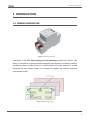
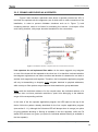
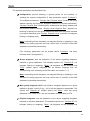
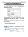
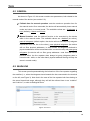
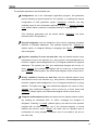
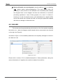
Linecoupler KNX-TP Line Coupler & Repeater Application Program version: [1.0] User Manual version: [1.0]_a www.zennio.com USER MANUAL ZN1SY-LCTP Zennio Linecoupler Contents 1 2 Introduction .................................................................................................................. 3 1.1 Zennio Linecoupler ................................................................................................ 3 1.2 Installation............................................................................................................. 5 Configuration................................................................................................................. 6 2.1 2.1.1 Zennio Linecoupler as a line coupler ................................................................. 6 2.1.2 Zennio Linecoupler as a repeater .................................................................... 10 2.2 3 4 General configuration ........................................................................................... 6 manual Function button ...................................................................................... 11 ETS parameterization (Linecoupler) ............................................................................ 12 3.1 Default parameterization .................................................................................... 12 3.2 General ................................................................................................................ 13 3.3 Main line.............................................................................................................. 13 3.4 Sub-line ................................................................................................................ 16 ETS parameterization (Linerepeater) .......................................................................... 17 4.1 Default parameterization .................................................................................... 17 4.2 General ................................................................................................................ 18 4.3 Main line.............................................................................................................. 18 4.4 Sub-line ................................................................................................................ 20 http://www.zennio.com Technical Support: http://zennioenglish.zendesk.com 2 Zennio Linecoupler 1 INTRODUCTION 1.1 ZENNIO LINECOUPLER Figure 1 Zennio Linecoupler Linecoupler is the KNX line-coupling and line-repeating solution from Zennio. This device is intended to couple two KNX twisted-pair lines together. Its flexibility makes it possible to connect a KNX sub-line to a KNX mainline or a KNX mainline to a KNX backbone line (line coupler mode), or to simply link together two sub-line segments (line repeater mode). Figure 2 Context (topology) http://www.zennio.com Technical Support: http://zennioenglish.zendesk.com 3 Zennio Linecoupler These are the most outstanding features of the device: Low power consumption. Galvanic insulation of the connected lines. Traffic filtering according to the project topology and to the built-in address table. Telegram dropping. Device configuration blocking (telegrams destined to physical addresses). Support for long messages (up to 250 bytes). Customizable pushbutton for triggering the manual mode, useful at runtime and for set-up and troubleshooting purposes. 6 lighting indicators (LEDs) for accurately showing the bus status of each line, making the detection of common situations (excessive bus load, message retransmissions, etc.) easier. Two alternative application programs permit configuring the device as a line coupler or as a repeater. http://www.zennio.com Technical Support: http://zennioenglish.zendesk.com 4 Zennio Linecoupler 1.2 INSTALLATION 1 2 3 4 5 1. 2. 3. 4. 5. 6. 7. 8. 9. 10. 11. Main line status LED. Main line traffic LED. Group address filter table status. Manual function button. Programming LED. Main line KNX connector. Secondary line status LED. Secondary line traffic LED. Physical address filter table status. Programming button. Secondary line KNX connector. 9 6 8 7 10 11 Figure 3 Element diagram As shown in Figure 3 each of the two KNX lines to be coupled must be connected to one of the two KNX bus connectors available (6, 11). After the connection, the line coupler can be conveniently mounted on the DIN rail by the usual procedure. This device does not need any external power supply since it is entirely powered through the main KNX bus (6). Note: each line (or line segment) being coupled requires a dedicated power supply. No power pass from one line to another is performed. The programming button (10) shown in Figure 3 may be pressed to set Linecoupler in programming mode. After a short press, the programming LED will light in red. The behaviour of the additional LEDs and the manual function button will be described in section 2.2. For detailed information about the technical features of Linecoupler, as well as information on security and on the installation process, please refer to the Datasheet included within the original packaging of the device and also available at http://www.zennio.com. http://www.zennio.com Technical Support: http://zennioenglish.zendesk.com 5 Zennio Linecoupler 2 CONFIGURATION 2.1 GENERAL CONFIGURATION Linecoupler can be used as a line coupler (for coupling both a sub-line to a mainline, or a mainline to a backbone line; the latter is normally referred to as “backbone coupler”) or as a repeater (for coupling two sub-line segments). A different application program is provided for each purpose. 2.1.1 ZENNIO LINECOUPLER AS A LINE COUPLER Figure 2 shows a typical scenario where Linecoupler can be installed. As a line coupler, the device may perform line coupling in the nodes marked as “LC”, where a sub-line connects to a mainline or a mainline connects to a backbone line. In both cases, Linecoupler offers an insulated coupling interface with the possibility of filtering the traffic according to the topology in the installation or to group-oriented criteria. In other words, Linecoupler will (or will not) let telegrams pass from one line to the other according to the parameterization. Another scenario is shown in Figure 4. 4.2.0 4.1.0 4.0.0 4.1.2 4.0.1 4.2.1 4.1.1 3.1.0 3.2.0 3.0.0 3.1.2 3.0.1 3.1.1 3.2.1 Figure 4 Line coupling scenario http://www.zennio.com Technical Support: http://zennioenglish.zendesk.com 6 Zennio Linecoupler Note: the individual address of a line coupler needs to be of the form X.Y.0 (or X.0.0 in the case of working as a backbone coupler). Regarding telegram filtering, the line coupler implements two complementary (and optional) filters: Group address filtering: ETS automatically generates a group address table according to the loaded project. This table is transferred to the line coupler when a device download is performed from ETS. Therefore, when a telegram containing a group address in the “destination address” field arrives to the line coupler, the line coupler will look up such address in the group table and eventually drop (block) the telegram or transmit it to the other side. Example: if the line coupler has been parameterized to filter group addresses from both lines, when it receives a telegram from the mainline destined to a group address (e.g., 2/5/13) it will check that there is a device in the sub-line with objects that have been assigned such group address (or that such address has at least been marked in ETS to pass through the line coupler; see Figure 5). If so, then the line coupler will let it pass. Otherwise, it won’t be transferred to the sub-line. The same would also apply to the inverse case (a telegram originating in the sub-line). Figure 5 ETS option to force passing a group address through the line coupler Physical address filtering: when the line coupler receives a telegram where the destination address is a physical/individual address (for example, during http://www.zennio.com Technical Support: http://zennioenglish.zendesk.com 7 Zennio Linecoupler downloads), it will compare such address with its own physical address. The physical address of the line coupler determines the line it belongs to, which then, and according to the parameterization, determines if the telegram will be routed or eventually dropped (blocked). This can be parameterized separately for the mainline and for the sub-line. Example: in the example shown in Figure 4, if the line coupler with address 3.2.0 reads a telegram on the mainline destined to the device with physical address 3.1.2, it will compare both addresses and conclude that 3.1.2 is not an address belonging to its line and will therefore not transmit it to its secondary line. Note: the device that sends a telegram needs to have been assigned a physical address that really corresponds to its line. In Figure 4, if the device with address 3.1.1 (let it be a KNX programmer, for instance) changes its address to 7.7.255, it will not be able to send telegrams to, for example, the device with address 4.0.1. For their part, the LED lights on the top of the device make it easy to monitor the status of the buses and to detect typical communication problems, as detailed next. Figure 6 LEDs Mainline status LED: shows the status of the primary bus. o OFF = error. o ON (green) = OK. o ON (orange/red) = manual function in execution. http://www.zennio.com Technical Support: http://zennioenglish.zendesk.com 8 Zennio Linecoupler Sub-line bus status LED: shows the status of the secondary bus. o OFF = error or secondary line not connected. o ON (green) = OK Mainline traffic LED: shows the traffic status in the primary bus. o BLINKING (green) = traffic. o OFF = no traffic. o BLINKING (red) = errors in the transmissions. Sub-line traffic LED: shows the traffic status in the secondary bus. o BLINKING (green) = traffic. o OFF = no traffic. o BLINKING (red) = errors in the transmissions. Group address (GA) filter status LED: shows the current configuration of the group address routing: o OFF = different routing for the main and the secondary lines. o ON (green) = filtering active. o ON (orange) = all group addresses routed. o ON (red) = routing blocked. Physical address (PA) filter status LED: shows the current configuration of the individual address routing: o OFF = different routing for the main and the secondary lines. o ON (green) = filtering active. o ON (yellow-orange) = all individual addresses routed. o ON (dark orange) = routing blocked. Note: please be careful not to confuse yellow-orange and dark orange. Please refer to section 3 for a detailed explanation of the different behaviours and parameterizations of the line coupler application program. http://www.zennio.com Technical Support: http://zennioenglish.zendesk.com 9 Zennio Linecoupler 2.1.2 ZENNIO LINECOUPLER AS A REPEATER Figure 2 also includes a particular case where a repeater (marked as “LR”) is required: two separate sub-line segments (one of which with no other connection to the installation, in order to prevent forbidden situations such as in Figure 7), both containing devices, need to be linked for extending the sub-line. Linecoupler offers such linking interface, with proper electrical insulation for the connections. 3.3.0 3.0.0 3.3.41 3.3.45 3.3.46 3.3.42 3.3.47 3.3.43 3.3.44 3.3.48 3.3.49 Figure 7 Forbidden situation: segment with two connections to the bus Line repeaters do not implement filter tables. As the name suggests, any telegram on one of the buses will be repeated to the other bus. It is therefore irrelevant whether the telegram originates on one side or another and whether it is destined to one side or another: both segments melt together. Therefore, the Linerepeater application program will only let transmitting or dropping every telegram destined to physical addresses, while no drop or filter options are provided for those destined to group addresses. Note: while the individual address of a line coupler does, the individual address of a repeater does not have particular restrictions, apart from belonging to the address range of the corresponding sub-line. In the case of the line repeater application program, the LED lights on the top of the device follow the pattern already described for the line coupler application program (see section 2.1.1), although the GA status LED will always show in orange (no option for group address blocking or filtering is available in the line repeater), while the PA status LED will never turn green (no option for individual address filtering is available in the line repeater). http://www.zennio.com Technical Support: http://zennioenglish.zendesk.com 10 Zennio Linecoupler Please refer to section 4 for a detailed explanation of the different behaviours and parameterizations of the line repeater application program. 2.2 MANUAL FUNCTION BUTTON Linecoupler features an additional pushbutton on the top cover, next to the status LEDs (see (4) in Figure 3). A 3-second press on this button will set the device in manual mode, thus activating a customizable manual function, and will turn the main bus status LED orange or red (depending on the previous status of the LED: green or off). Depending on the parameterized manual function, other LEDs may also change their colours. If the manual function button is pressed again for 3 seconds (or if the parameterized fallback timer expires), the device will leave the manual mode and recover the normal mode. Note that switching from the normal mode to the manual mode and then back to the normal mode does not cause a loss of the previously downloaded parameters. For both the line repeater and the line coupler application programs, the selectable manual functions are: disabled, pass all telegrams, pass physical telegrams and pass group telegrams. Please refer to sections 3.2 and 4.2 for the parameterization in ETS of the manual function and for a detailed description of the different options. http://www.zennio.com Technical Support: http://zennioenglish.zendesk.com 11 Zennio Linecoupler 3 ETS PARAMETERIZATION (LINECOUPLER) To begin with the parameterization process of the device, it is necessary, once the ETS program has been opened, to import the database of the product (Linecoupler application program). Figure 8 Properties of the Linecoupler application program Next, the device should be added to the project where desired. And then, one click on the device with the secondary mouse button will permit selecting "Edit parameters", in order to start the configuration. The following sections provide a detailed explanation about each of the different parameters of the device. 3.1 DEFAULT PARAMETERIZATION When entering the parameter edition of Linecoupler for the first time, a window similar to Figure 9 will be shown, where three main tabs are available: General, Main line and Sub-line. Note that this application program does not implement communication objects. Figure 9 General http://www.zennio.com Technical Support: http://zennioenglish.zendesk.com 12 Zennio Linecoupler 3.2 GENERAL As shown in Figure 9, this screen contains two parameters, both related to the manual mode of the device (see section 2.2): Fallback time for manual operation: sets the maximum operation time for the manual mode. Once exceeded, the device will automatically leave manual mode and return to normal mode. The available values are: 10 minutes, 1 hour (default), 4 hours and 8 hours. Manual function: sets the desired function to be executed by the device while in the manual mode. The available values are: disabled (no action), pass all telegrams (default option; the device will not filter/drop any telegram transferred from one line the other), pass physical telegrams (the device will not filter/drop physical addresses; in other words, all telegrams destined to physical addresses will be transmitted while in manual mode; on the other hand, group telegram filtering will stay the same as in normal mode) and pass group telegrams (the device will not filter/drop group addresses; in other words, the group address filter table will stay disabled while in manual mode; on the other hand, physical address filtering will stay the same in normal mode). 3.3 MAIN LINE This screen permits parameterizing the behaviour of the line coupler regarding the mainline, that is, when the telegrams are being transferred towards the mainline. Figure 10 Mainline http://www.zennio.com Technical Support: http://zennioenglish.zendesk.com 13 Zennio Linecoupler The available parameters are described next: Configuration: permits selecting a general preset for the mainline, or enabling the manual configuration of each parameter (option “Configure”). The available presets are: “Groups: filter; Physical: block” (enables the group address filtering and drops all telegrams destined to physical addresses), “Groups, Physical: filter” (default option; enables both the group address and the physical address filtering), “Groups: route; Physical: filter” (performs no blocking or filtering over the group address but does filter telegrams destined to physical addresses) and “Groups, Physical: route” (performs no telegram filtering or dropping at all). Note: transmitting all the telegrams (no telegram filtering or dropping) is only intended for testing purposes and may cause risks or conflicts in the KNX installation if permitted permanently. (The following parameters will be locked unless “Configure” has been selected under “Configuration”). Group telegrams: sets the behaviour of the device regarding telegrams destined to group addresses. The available options are “Transmit all” (no telegram filtering or dropping), “Block” (all telegrams will be dropped) and “Filter” (default option; telegrams will be filtered, dropping only the corresponding ones, according to the filter table; see section 2.1.1). Note: transmitting all the telegrams (no telegram filtering or dropping) is only intended for testing purposes and may cause risks or conflicts in the KNX installation if permitted permanently. Main group telegrams 14/15: sets whether telegrams destined to a group address in groups 14 and 15 (e.g., 14/1/1) will be dropped or transmitted. The options are “Transmit all” (default option) and “Block”. Note that group addresses 14.X.Y and 15.X.Y are not included in the filter table by ETS. Physical telegrams: sets the behaviour of the device regarding telegrams destined to individual addresses. The available options are “Transmit all” (no telegram filtering or dropping), “Block” (all telegrams will be dropped) and http://www.zennio.com Technical Support: http://zennioenglish.zendesk.com 14 Zennio Linecoupler “Filter” (default option; telegrams will be filtered, dropping the corresponding ones; see section 2.1.1). Note: transmitting all the telegrams (no telegram filtering or dropping) is only intended for testing purposes and may cause risks or conflicts in the KNX installation if permitted permanently. Physical: repetition if errors on main line: sets the desired reaction upon transmission errors in the mainline (e.g.: busy receiver, acknowledgement not received, negative acknowledgement, etc.) of telegrams destined to physical addresses. The options are “No” (the undelivered telegram will not be resent), “Normal” (default option; the undelivered telegram will be re-sent up to 3 times) and “Reduced” (the undelivered telegram will be re-sent once). Group: repetition if errors on main line: sets the desired reaction upon transmission errors in the mainline (e.g.: busy receiver, acknowledgement not received, negative acknowledgement, etc.) of telegrams destined to a group address. The options are “No” (the undelivered telegram will not be re-sent), “Normal” (default option; the undelivered telegram will be re-sent up to three times) and “Reduced” (the undelivered telegram will be re-sent once). Telegram confirmations on line: sets when the line coupler should confirm (by sending an immediate ACK message) the reception of telegrams. Selecting “If routed” (default option) will make the line coupler respond with an IACK message only if the received telegram is routed towards the mainline, while “Always” will make the line coupler send a confirmation for every telegram it receives, even if not routed to the line on the other side. Send confirmation on own telegrams: permits enabling (“Yes”) or disabling (“No”; default option) self-acknowledgment. This extra feature offers the possibility to send an ACK to the destination line immediately after passing the telegram itself, so the telegram will show as confirmed on it (therefore preventing repetitions in case of faulty projects, etc.) even if no device is receiving it. In case of reception errors on the destination line, negative ACKs sent by the devices will overwrite this ACK, so having this parameter enabled will cause no damage or information loss. http://www.zennio.com Technical Support: http://zennioenglish.zendesk.com 15 Zennio Linecoupler 3.4 SUB-LINE This screen permits parameterizing the behaviour of the line coupler regarding the sub-line, that is, when telegrams are being transferred towards the sub-line. As shown in Figure 11, the available parameters are completely analogous to those in the “Main line” tab. Figure 11 Subline Please refer to section 3.3 for a detailed description of these parameters, taking into account that section 3.3 applies to the mainline instead of the sub-line. http://www.zennio.com Technical Support: http://zennioenglish.zendesk.com 16 Zennio Linecoupler 4 ETS PARAMETERIZATION (LINEREPEATER) To begin with the parameterization process of the device, it is necessary, once the ETS program has been opened, to import the database of the product (Linerepeater application program). Figure 12 Properties of the Linerepeater application program Next, the device should be added to the project where desired. And then, one rightclick on the device will permit selecting "Edit parameters", in order to start the configuration. In the following sections a detailed explanation can be found about each of the different parameters of the device. 4.1 DEFAULT PARAMETERIZATION When entering the parameter edition of Zennio Linecoupler for the first time, a window similar to Figure 13 will be shown, where three main tabs are available: General, Main line and Line. Note that this application program does not implement communication objects. Figure 13 General http://www.zennio.com Technical Support: http://zennioenglish.zendesk.com 17 Zennio Linecoupler 4.2 GENERAL As shown in Figure 13, this screen contains two parameters, both related to the manual mode of the device (see section 2.2): Fallback time for manual operation: sets the maximum operation time for the manual mode. Once exceeded, the device will automatically leave manual mode and return to normal mode. The available values are: 10 minutes, 1 hour (default), 4 hours and 8 hours. Manual function: sets the desired function to be executed by the device while in the manual mode. The available values are: disabled (no action), pass all telegrams (default option; the device will not filter/drop any telegram transferred from one line to the other), pass physical telegrams (the device will not filter physical addresses; in other words, all telegrams destined to physical addresses will be transmitted while in manual mode) and pass group telegrams (the device will not filter group addresses –note that this has no practical effect; the line repeater does always let group telegrams pass in normal mode– while, on the other hand, physical address filtering will stay the same in normal mode). 4.3 MAIN LINE This screen permits parameterizing the behaviour of the line repeater regarding the mainline (i.e., when the telegrams travel towards the bus connected to the terminal on the left; see Figure 3). Note that in the case of the line repeater both lines belong to the same hierarchical range, although they will still be referred here to as “mainline” and “sub-line”, in order to distinguish them. Figure 14 Mainline http://www.zennio.com Technical Support: http://zennioenglish.zendesk.com 18 Zennio Linecoupler The available parameters are described next: Configuration: as in the Linecoupler application program, this parameter permits selecting a general preset for the mainline, or enabling the manual configuration of each parameter (option “Configure”). However, the only available preset in the Linerepeater application program is “Groups, Physical: route (default option; performs no telegram filtering or dropping at all). (The following parameters will be locked unless “Configure” has been selected under “Configuration”). Physical telegrams: sets the behaviour of the device regarding telegrams destined to individual addresses. The available options are “Transmit all” (default option; no telegram filtering or dropping) and “Block” (all telegrams will be dropped). Physical: repetition if errors on main line: sets the desired reaction upon transmission errors in the mainline (e.g.: busy receiver, acknowledgement not received, negative acknowledgement, etc.) of telegrams destined to physical addresses. The options are “No” (the undelivered telegram will not be resent), “Normal” (the undelivered telegram will be re-sent up to three times) and “Reduced” (default option; the undelivered telegram will be re-sent once). Group: repetition if errors on main line: sets the desired reaction upon transmission errors in the mainline (e.g.: busy receiver, acknowledgement not received, negative acknowledgement, etc.) of telegrams destined to a group address. The options are “No” (the undelivered telegram will not be re-sent), “Normal” (the undelivered telegram will be re-sent up to three times) and “Reduced” (default option; the undelivered telegram will be re-sent once). Telegram confirmations on line: sets when the line repeater should confirm (by sending an immediate ACK –or IACK– message) the reception of telegrams. Selecting “If routed” (default option) will make the line repeater respond with an IACK message only if the received telegram is routed towards the sub-line, while “Always” will make the line repeater send a confirmation for every telegram it receives, even if not routed to the line on the other side. http://www.zennio.com Technical Support: http://zennioenglish.zendesk.com 19 Zennio Linecoupler Send confirmation on own telegrams: permits enabling (“Yes”) or disabling (“No”; default option) self-acknowledgment. This extra feature offers the possibility to send an ACK to the destination line immediately after sending the telegram itself, so the telegram will show as confirmed on it (therefore preventing repetitions in case of faulty projects, etc.) even if no device is receiving it. In case of reception errors on the destination line, negative ACKs sent by the devices will overwrite this ACK, so having this parameter enabled will cause no damage or information loss. 4.4 SUB-LINE This screen permits parameterizing the behaviour of the line repeater regarding the sub-line (i.e., when the telegrams travel towards the bus connected to the terminal on the right; see Figure 3). As shown in Figure 15, the available parameters are completely analogous to those in the “Main line” tab. Figure 15 Sub-line Please refer to section 4.3 for a detailed description of these parameters, taking into account that section 4.3 applies to the mainline instead of the sub-line. http://www.zennio.com Technical Support: http://zennioenglish.zendesk.com 20 Join and send us your inquiries about Zennio devices: http://zennioenglish.zendesk.com Zennio Avance y Tecnología S.L. C/ Río Jarama, 132. Nave P-8.11 45007 Toledo (Spain). Tel. +34 925 232 002. Fax. +34 925 337 310. www.zennio.com [email protected]