1
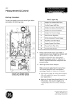
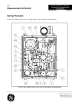
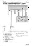
GE
Measurement & Control
Startup and Shutdown Procedure
for Aurora Trace Sample System
with Verification System
916-135, Rev C
May 2013
Startup Procedure
To start your sample system, refer to the figure below and complete the following steps:
7
26
23
5
24
22
1
4
2
21
9
3
25
8
10
11
6
Aurora Trace Sample System with H2O Verifier Option
1100 Technology Park Drive
Billerica, MA 01821-4111
Web: www.ge-mcs.com
Startup Procedure for Aurora Trace Sample System
May 2013
Table 1: Figure Key
2 of 4
1
Sample Gas Isolation Ball Valve
2
Verifier Bypass Ball Valve
3
Sample Gas Bypass Metering Valve
4
Sample Gas Pressure Regulator
5
Sample Gas Pressure Gauge
6
Back Pressure Regulator
7
Orifice Upstream Pressure Gauge
8
Multi-Pass Cell Flow Meter
9
Sample Bypass Flow Meter
10
Process/Test 3-Way Valve
11
Vacuum Pump Switch
21
Verifier Isolation 3-Way Valve
22
Verifier Isolation Ball Valve
23
Verifier Bypass Metering Valve
24
Purifier Isolation Ball Valve
25
Purifier Isolation Ball Valve
26
Verifier Bypass Flow Meter
916-135C
May 2013
1. Before connecting the unit to a gas supply at
sample inlet port, ensure Sample Gas Isolation Ball
Valve (Item #1) is closed. Make sure all
mechanical connections have been properly
installed according to section 2.7 in the User’s
Manual. Required connections: sample inlet and
pump discharge.
2. Warm-up Aurora Trace analyzer and verifier.
Startup Procedure for Aurora Trace Sample System
b. Open junction box cover. Make sure temperature
is set mid-scale. If not, use a flat head screw
driver to set mid-scale. Allow 15 minutes to
warm up. Remove the cap covering the Sample
Gas Pressure Regulator adjustment screw (Item
# 4).
c. Remove the cap covering the Sample Gas
Pressure Regulator adjustment screw (Item #4).
a. Make sure power supply lines for Aurora Trace
and vacuum pump have been wired properly
according to Section 2.7 in the User’s Manual.
d. Using a 5/32” hex driver, turn the regulator
adjustment screw fully counter-clockwise
(minimum pressure output).
b. Turn on power supply for Aurora Trace analyzer.
(This will warm up verification system and
stabilize Aurora Trace analyzer laser
temperature.)
e. Open Item #1 (Sample Gas Isolation Ball Valve).
c. Make sure Vacuum Pump Switch (Item #11) at
OFF position. Turn on power supply to the
vacuum pump. (This will warm up multi-pass
cell.)
3. Set up valves positions.
a. Open Items #21 and #22
(Verifier Isolation 3-way Valve, handle pointing
inward, Verifier Isolation Ball Valve).
b. Fully close Item #2
(Verifier Bypass Valve).
c. Fully close Item #3
(Sample Gas Bypass Metering Valve).
d. Close Item #23
(Verifier Bypass Metering Valve).
e. Open Items #24 and #25
(Purifier Isolation Ball Valves).
f. Make sure Process/Test 3-way Valve (Item #10)
handle points upward.
4. Set upstream pressure to 50 psig.
If an electrically heated Sample Gas Pressure
Regulator (Item #4) is installed in Aurora Trace sample
system, follow these steps:
a. Locate junction box for setting temperature of
the heated Sample Gas Pressure Regulator (Item
#4). It is right below the heated Sample Gas
Pressure Regulator marked as #4.
916-135C
f. Turn the regulator adjustment screw slowly
clockwise while observing Item #5 (Sample Gas
Pressure Gauge) to 50 ±5 psig.
g. Slowly open Item #3 (Sample Gas Bypass
Metering Valve) until the desired flow is
achieved at Item #9 (Sample Bypass Flow
Meter).
h. If Sample Gas Pressure Gauge (#5) pressure
reading oscillates, go back to step b and increase
temperature set point to the next level. Allow 15
minutes to warm up. If Sample Gas Pressure
Gauge (#5) becomes stable, raise temperature set
point one more level, then close junction box. If
not, repeat above process until Sample Gas
Pressure Gauge (#5) is stable and then raise
temperature set point one more level, then close
junction box.
i. Try to avoid setting the heated Sample Gas
Pressure Regulator (Item #4) to its maximal
temperature, if possible. The Heated Sample Gas
Pressure Regulator (Item #4) could be
overheated if set at maximal temperature for an
extended period of time when there is no gas
flowing through it.
If a standard un-heated, Sample Gas Pressure
Regulator (Item#4) is installed in Aurora Trace
sample system, follow these steps:
a. Turn the Sample Gas Pressure Regulator (Item
#4) fully counter-clockwise (minimum pressure
output).
b. Open Item #1 (Sample Gas Isolation Ball Valve).
3 of 4
Startup Procedure for Aurora Trace Sample System
c. Turn the Sample Gas Pressure Regulator (Item
#4) slowly clockwise while observing Item #5
(Sample Gas Pressure Gauge) to 50 ±5psig.
d. Slowly open Item #3 (Sample Gas Bypass
Metering Valve) until the desired flow is
achieved at Item #9 (Sample Bypass Flow
Meter).
5. Turn ON Vacuum Pump Switch (Item #11). Ensure
pump discharge is not restricted.
6. Set up verification system's orifice flow and bypass
flow.
a. Go to Aurora Trace display Main Menu/
Settings/Verifier/Diags.
b. Display following readings
d. Adjust Item #6 (Back Pressure Regulator) while
observing the sample pressure reading on the
unit display. Set the pressure to read 2.5±0.1 on
the display.
e. Re-install the pressure regulator adjustment
screw cap if an electrically heated Sample Gas
Pressure Regulator (Item #4) is installed in
Aurora Trace sample system.
Shutdown Procedure
1. Turn Vacuum Pump Switch (item #11) OFF.
2. Close the Sample Gas Isolation Ball Valve (item
#1) to depressurize the system. Monitor the Sample
Gas Pressure Gauge (item #5) to drop to zero.
•
Perm tube temperature (Prf):
warming up to 50°C
•
Preheat temperature (Mnf):
warming up to 50°C
4. Turn the Back Pressure Regulator (item #6) fully
counter-clockwise.
•
Orifice Flow (Orf):
controlled at 1860 sccm
5. Close the following valve(s):
Item #3Sample Gas Bypass Metering Valve:
Item #21 Verifier Isolation 3-Way Valve
Item #22 Verifier Isolation Ball Valve
Item #23 Verifier Bypass Metering Valve
Item #24 Purifier Isolation Ball Valve
Item #25 Purifier Isolation Ball Valve
c. Slowly adjust Verifier Bypass Metering Valve
(Item #23) so that Verifier Bypass Flow Meter
(Item #26) reads 48 LPH (1.7 SCFH)
d. Wait until Orifice Flow (Orf) stable at 1860
sccm on display
e. Adjust Item #23 slightly so that Item 26 reads 60
LPH (2.1 SCFH).
f. Repeat d and e so that Item #26 reads 60 LPH
(2.1 SCFH) and Orifice Flow (Orf) stable at
1860 sccm on display.
7. Adjust internal sample pressure to 2.5psia
Make sure sample pressure reading (psia) is configured
on Aurora Trace display.
a. Adjust Item #6 (Back Pressure Regulator) so
that Item #7 (Orifice Upstream Pressure Gauge)
reads 12 psig.
b. Allow 15 minutes for system pump down.
c. Observe Item #8 (Multi-pass Cell Flow Meter)
to be at full scale.
4 of 4
May 2013
3. Turn the Sample Gas Pressure Regulator (item #4)
fully counter-clockwise.
Total sample gas flow rate from Aurora Trace outlets
are flow rate from Sample Bypass Flow Meter (# 9)
plus flow rate through vacuum pump. Flow rate
through vacuum pump varies from unit to unit, but it
cannot exceed 1.86 slpm when a verification system is
installed.
Sample systems for trace moisture applications will
require some time to “dry-down” for reaching the
actual process moisture level. Typically 12-24 hours
operation with process gas flowing at normal flow rates
will “dry” the system, but this will vary depending on
process conditions, length of tubing runs and storage
conditions for the Aurora Trace prior to installation.
Once the analyzer has reached process moisture levels,
it is recommended to run the verification cycle 6-8
times to ensure all components within are adequately
dry to provide accurate verification cycle values.
916-135C