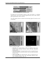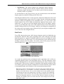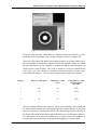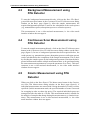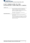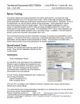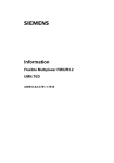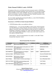
1
Version 6
User Manual
FPA
© 2006 BRUKER OPTIK GmbH, Rudolf-Plank-Str. 27, D-76275 Ettlingen, www.brukeroptics.com
All rights reserved. No part of this publication may be reproduced or transmitted in any form or by any
means including printing, photocopying, microfilm, electronic systems etc. without our prior written
permission. Brand names, registered trade marks etc. used in this manual, even if not explicitly marked
as such, are not to be considered unprotected by trademarks law. They are the property of their respective owner.
The following publication has been worked out with utmost care. However, Bruker Optik GmbH does
not accept any liability for the correctness of the information. Bruker Optik GmbH reserves the right to
make changes to the products described in this manual without notice.
This manual is the original documentation for the OPUS spectroscopic software.
Table of Contents
1
2
Introduction . . . . . . . . . . . . . . . . . . . . . . . . . . . . . . . . . . . . . . . . . . . . . . 1
Hardware Requirements . . . . . . . . . . . . . . . . . . . . . . . . . . . . . . . . . . . . 3
3
Configuring the Hardware . . . . . . . . . . . . . . . . . . . . . . . . . . . . . . . . . . 5
3.1
3.2
3.3
4
Continuous Scan Measurements using FPA Detector . . . . . . . . . . . 11
4.1
4.2
4.3
4.4
4.5
4.6
5
Setting up the Transient Recorder . . . . . . . . . . . . . . . . . . . . . . . . . . . . . . . . . .5
Setting up the Imaging Device . . . . . . . . . . . . . . . . . . . . . . . . . . . . . . . . . . . .6
Setting up the Velocity . . . . . . . . . . . . . . . . . . . . . . . . . . . . . . . . . . . . . . . . . .9
Measurement Parameters . . . . . . . . . . . . . . . . . . . . . . . . . . . . . . . . . . . . . . . .11
Video-assisted, continuous Scan Measurement using FPA Detector . . . . . .15
4.2.1
Video Mode Interface . . . . . . . . . . . . . . . . . . . . . . . . . . . . . . . . . . .15
4.2.2
Pop-up Menu of the Live FPA Image . . . . . . . . . . . . . . . . . . . . . . .17
Background Measurement using FPA Detector . . . . . . . . . . . . . . . . . . . . . .26
Continuous Scan Measurement using FPA Detector . . . . . . . . . . . . . . . . . .26
Kinetic Measurement using FPA Detector . . . . . . . . . . . . . . . . . . . . . . . . . .26
Displaying the Measurement Results . . . . . . . . . . . . . . . . . . . . . . . . . . . . . .27
Step Scan Measurement using FPA Detector . . . . . . . . . . . . . . . . . . 29
5.1
5.2
5.3
5.4
Measurement Parameters . . . . . . . . . . . . . . . . . . . . . . . . . . . . . . . . . . . . . . . .29
Video-assisted step scan Measurement using FPA Detector . . . . . . . . . . . . .31
5.2.1
Video Mode Interface . . . . . . . . . . . . . . . . . . . . . . . . . . . . . . . . . . .31
5.2.2
Pop-up Menu of the Live FPA Image . . . . . . . . . . . . . . . . . . . . . . .31
Non-video-assisted Step Scan-Measurement using FPA Detector . . . . . . . .33
Displaying the Measurement Results . . . . . . . . . . . . . . . . . . . . . . . . . . . . . .34
iii
iv
1
Introduction
The software package OPUS/FPA allows data acquisition using the microscope
HYPERIONTM 3000 or the external sample chamber IMAC in conjunction
with an optional FPA detector (Focal Plane Array Detector). The FPA detector
is a multi-element detector, i.e. the detector consists of a matrix with 64 x 64 or
128 x 128 detector elements. Similar to the CCD chip of a video camera, the
detector elements lie equidistant in a plane. In contrast to a single-element
detector (e.g. MCT detector), the FPA detector can acquire data simultaneously
at as many points as the detector has elements (pixel) with one single measurement. An advantage of this detector type is the extremely short measurement
time when analyzing sample surfaces. Normally, a measurement using the FPA
detector takes only a few seconds.
With the software package OPUS/FPA you can perform both continuous scan
measurements as well step scan measurements using the FPA detector. In case
you want to create and save video images as well, the software package
OPUS/VIDEO is required. For the control of the computer-controlled x/y-stage
you need the software package OPUS/MAP. To display and evaluate the measurement data the software package OPUS/3D is necessary.
Bruker Optik GmbH
OPUS/FPA
1
Introduction
2
OPUS/FPA
Bruker Optik GmbH
2
Hardware Requirements
Computer System
For measurements using the FPA detector at least one free PCI slot for the FPA
frame grabber card and a RS232 port are necessary. In addition, video-assisted
measurements require either a PCI video frame grabber card or a digital camera
that is connected to a firewire (IEEE 1394) or USB interface. In case you work
with a computer-controlled x/y-stage, you need also an external LANG controller that is connected to a RS232 interface or the internal LSTEP board that
requires a long PCI slot.
For measurements with a continuous scanner movement (continuous scan measurements), there has to be an electrical connection between the optics and the
FPA detector to synchronize the digitalization of the IR images with the scanner
movement.
In case of accumulating measurements, all raw data are buffered and averaged
in the RAM so that they need not read in again from the hard disk after the measurement. This involves a considerable saving of time. During this kind of measurement, a huge amount of data is generated which needs to be buffered in the
RAM. In the following table, the required RAM storage capacity depending on
the pixel number, the resolution and the band width is listed. (The listed values
hold true for the acquisition mode Double Sided, Forward-Backward).
Number of FPA
RAM Storage Capacity
Resolution [cm-1] Band Width [cm-1]
Detector Pixels
[MByte]
64 x 64
2
15800
1792
64 x 64
2
7900
903*
64 x 64
2
3950
460*
64 x 64
4
3950
240*
128 x 128
2
1580
7167
128 x 128
2
7900
3614
128 x 128
2
3950
1838
128 x 128
4
3950
950*
A logical conclusion drawn from this fact is that the PC should be equipped
with a RAM having the highest possible storage capacity. But without additional provisions, Windows, however, can at most manage only a memory
address space of 2 GByte. So, a RAM storage capacity of 2 GByte is a reasonable upper limit. In the above table, the cases marked by an asterisk can be realized with a 2 GByte RAM.
Bruker Optik GmbH
OPUS/FPA
3
Hardware Requirements
In case of kinetic measurements, the generated raw data are not buffered and
averaged in the RAM but they are written on the hard disk in real time. This
implies a considerably high data rate. If the data are read out at the FPA detector
with 80% of the maximum frame rate as usual the data rate is 23.6 MByte/sec
(in case of a FPA detector with 64 x 64 pixel and a maximum frame rate of
3773 Hz) or 40.25 MByte/sec (in case of a FPA detector with 128 x 128 pixel
and a maximum frame rate of 1610 Hz). See the following table:
Pixel number of Frame Rate
FPA detectors
[Hz]
Bytes/Frame
[KByte]
Data Rate
[MByte/sec]
64 x 64
0.8 x 3773
8
23.6
128 x 128
0.8 x 1610
32
40.25
To ensure these data rates without frame loss during a continuous measurement
the computer ought not to perform other operations than acquiring data. Moreover, the data acquisition ought not to be interfered by other programs and services or mouse or keyboard inputs. To ensure an undisturbed data acquisition,
make sure that the following conditions are fulfilled:
• The computer ought not to be integrated into a LAN.
• No additional software programs ought to be installed on the computer.
• Close all services that are not required.
• During data acquisition, do not press any mouse key or keyboard button.
In case of continuous scan measurements using the FPA detector, the FPA
images are digitized, collected and accumulated between two mirror positions.
This reduces the measurement time considerably but at the same time it makes
high demands on the PC because a continuous minimum data transfer rate has
to be ensured. Especially the newer FPA detectors are suitable for continuous
scan measurements as they allow frame rates of several KHz.
Optics
Step scan measurements using a FPA detector require a spectrometer that is
equipped with the step scan option. In case of this measurement mode, each
mirror position is approached separately to accumulate and read out the images
of the FPA detector. This measurement mode does not make high demands on
the clock frequency which, however, leads to longer measurement times.
4
OPUS/FPA
Bruker Optik GmbH
Setting up the Transient Recorder
3
Configuring the Hardware
3.1
Setting up the Transient Recorder
After the installation of the FPA-frame grabber card in the PC, you have to
setup this card in OPUS under Transient recorder. To do this, select in the Measure menu the function Optic Setup and Service. The dialog box Optic Setup
and Service opens. Click on the Devices/Options tab. Activate the Transient
recorder check box (figure 1) and click on the Setup button.
Figure 1: Setting up the Transient Recorder
The dialog window Devices/Options (figure 2) opens. Click on the Add new
item button and enter for example 8=FPA1(pcdig.dll). You can define any number you like, however, the number (e.g. 8) at the beginning of the row should
occur only once in the list. And you can specify also any name you like (e.g.
FPA1). However, the supplement in brackets (pcdig.dll) is of crucial importance as it invokes the function library that is necessary for the FPA detector
operation. In case the supplement in brackets is misspelled, the program library
for FPA frame grabber can not be found. (The supplement is not case-sensitive.)
Bruker Optik GmbH
OPUS/FPA
5
Configuring the Hardware
Figure 2: Setting up the Transient Recorder
It is recommended to select only those transient recorders which the PC is actually equipped with. If there are no PAD boards available for time resolved step
scan measurements, for example, deselect all entries beginning with PAD.
First, click on OK button and then on the Save Setting button in the Optic Setup
and Service dialog window (figure 1).
3.2
Setting up the Imaging Device
The imaging device is the combination of the available optics (microscope,
IMAC), the capture device (video frame grabber with analog or digital camera),
the x/y-stage and the FPA frame grabber card. To set up the imaging device,
select in the Measure menu the Optic Setup and Service function and click on
the Devices/Options tab. Activate the Imaging Device check box and click on
the Setup button. See figure 3.
6
OPUS/FPA
Bruker Optik GmbH
Setting up the Imaging Device
Figure 3: Setting up the Imaging Device
The Devices/Options dialog box (figure 4) appears. This dialog box contains all
imaging devices you have set up so far. If you want to set up a new imaging
device, click on the Add new item button and enter a character string having the
following syntax: number<equals sign<description of the imaging device (e.g.
1=Hyp3000mitFPA).
Note: You can enter any number you like. However, make sure that a number is
assigned only to one imaging device in the list. When you define a description of
the imaging device take into consideration that this description can be used as file
name.
Figure 4: Dialog Box Devices/Options - Imaging Device
To set up an imaging device, first click on the entry in question and then on the
Setup button next to the entry field. (See figure 4.) The Setup for Imaging
Device dialog box appears:
Bruker Optik GmbH
OPUS/FPA
7
Configuring the Hardware
Figure 5: Dialog Box Setup for Imaging Device
All options and settings that have not yet been set up are indicated by a warning
sign
next to the corresponding button. A warning sign disappears after the
setup of an option has been completed. Before starting a measurement, you
have to set up all options and settings with a warning sign. For more information about setting up the imaging device refer to the OPUS/VIDEO Manual.
As you want to perform a measurement using a FPA detector you have to select
this detector. To do this, click on the FPA Device button. (See figure 5.) The
following dialog box opens:
Figure 6: Selecting the FPA Detector
Select the FPA detector in question and click on the OK button.
8
OPUS/FPA
Bruker Optik GmbH
Setting up the Velocity
3.3
Setting up the Velocity
For devices which communicate with the PC using an acquisition processor
(AQP) you have to set up a variable velocity (i.e. that also other than the predefined velocities can be specified) before the measurement is started, provided
your device is capable of step scan measurements.
To do this, select in the Measure menu the Optic Setup and Service function and
click on the Devices/Options tab. Activate the Velocity check box and click on
the Setup button. See figure 7.
Figure 7: Setting up the Velocity
As a result, the following dialog box opens:
Figure 8: Selecting the variable Velocity
Bruker Optik GmbH
OPUS/FPA
9
Configuring the Hardware
If the list already includes an entry for a variable velocity (-1=Variable Hz),
select it. Otherwise, you have to add such an entry by clicking on the Add new
item button and selecting it afterward.
For devices that are connected to the PC via Ethernet, you need not to set up a
variable velocity.
10
OPUS/FPA
Bruker Optik GmbH
Measurement Parameters
4
Continuous Scan Measurements using FPA Detector
Select in the Measure menu the Continuous Scan FPA Measurement function.
As a result, the corresponding dialog window opens. See figure 9.
Figure 9: Continuous Scan FPA Measurement - Basic
4.1
Measurement Parameters
Most pages of this dialog window (Advanced, Optic, Acquisition and FT) are
identical to a great extend to the corresponding pages of Advanced Measurement dialog window. For information about these measurement parameters
refer to the OPUS Reference Manual. For a detailed description of the XY Stage
page, see OPUS/VIDEO Manual.
Basic
Select in the Imaging device drop-down list the option you have set up before,
as described in chapter 3. A field with a yellow background indicates that the
FPA detector has to be evacuated as soon as possible. (For information about
evacuating the FPA detector refer to the HYPERION User Manual.)
Bruker Optik GmbH
OPUS/FPA
11
Continuous Scan Measurements using FPA Detector
FT
Select in the Phase Correction mode drop-down list either the option Power/No
Peak Search or Mertz/No Peak Search to prevent that the interferogram maximum (peak) is searched for every interferogram separately. Otherwise, in case
of weak signal, the peak position of several interferograms may be found too far
away from the desired position. As a consequence of this, the spectra will be
incompatible and the spectra calculation will be canceled.
Optic
For devices which communicate with the PC using an acquisition processor
(AQP), you have to define a variable velocity. To do this, you have to set up a
variable velocity beforehand. See chapter 3, section 3.3.
Select in the Velocity drop-down list the option Variable (Hz) and enter the
desired velocity (in Hz) in the field that appears on the right of the drop-down
list. (See figure 10.) This value is the effective scanner velocity at a bandwidth
of 7900cm-1.
Figure 10: Specifying a variable Scanner Velocity
Values smaller than 100 cause an error status that is indicated by a red background of the entry field and the error message Velocity should be bigger than
100. (The error message appears when you position the cursor on the red entry
field.)
Note: The reason why the lower limit value has been set to 100 is the unstable
control of the scanner movement with smaller scanner velocity values.
Figure 11: Scanner Velocity Value is too small
Also the allowable maximum scanner velocity value has been limited; it has to
be smaller than 80% of the specified frame rate of the FPA detector. Otherwise,
an error status is displayed as well by a red background of the entry field and an
error message.
Check Signal
The Check Signal page of the Continuous Scan FPA Measurement dialog window differs significantly from corresponding page of the Measurement dialog
window.
12
OPUS/FPA
Bruker Optik GmbH
Measurement Parameters
In the ‘oscilloscope display’, the intensity values of all pixels (i.e. detector elements of the FPA detector) are displayed versus the pixel number. (See
figure 12.) This kind of display allows you to recognize immediately pixels
with a too high signal intensity. You can set the signal level optimally by changing the parameters Frame Rate, Offset and Gain. See figure 13a.
Figure 12: FPA-Detector Setup
Frame Rate
The frame rate (Hz) is the velocity with which the images are read out from the
detector.
For the FPA detector SBFJ108 applies the following: The smaller the frame rate
value is the more signal is detected by each detector element. However, do not
enter a too small frame rate value as this leads to a detector overload. See
figure 14. For transmission measurements, enter a frame rate value of 252 or
315Hz and for reflection measurements use a frame rate of 180 or 210Hz.
For the FPA detector SBF161 applies the following: Select the maximum possible frame rate value (3773Hz) and change the integration value correspondingly.
Integration
In case of FPA detector SBFJ108 of which the integration time is a fixed percentage of the frame rate you can only change the frame rate value in order to
optimize the signal intensity. In this case the Integration drop-down list is
grayed.
FPA detectors (SBF161) for which the frame rate and the integration time can
be changed independently from each other, select the highest possible frame
rate value (3773Hz) and change only the integration value in such a way that the
signal intensity is sufficient but neither the upper nor the lower signal values are
cut off.
Bruker Optik GmbH
OPUS/FPA
13
Continuous Scan Measurements using FPA Detector
Offset
The parameter Offset is used to shift the signal in y-direction. The Offset value
is set optimally when the signal intensity is as high as possible with no sample
in the optical path (in case of background measurement) and when the signal
intensity is as low as possible with an interrupted IR-beam (e.g. by switching to
the VIS mode or by placing an IR-nontransparent material in the optical path).
Gain
If the signal intensity is not sufficient after increasing the integration time you
can amplify the signal using the parameter Gain. Note, however, that in case of
a too high signal amplification the noise increases to the same degree.
Ensure that the detector is not overloaded. In the IR mode, the signal intensity
values should not be above 50% of the maximum value (16383) in oscilloscope
window. In the VIS mode, the signal intensity values should not fall below 10%
of the maximum value (16383) in the oscilloscope window.
Note: In case of step scan measurements, in the IR mode, the signal intensity values should not be above 15% of the maximum value (16383) in the oscilloscope
window and in the VIS mode, the signal intensity values should not fall below
10% of the maximum value (16383) in the oscilloscope window.
Another possibility of optimizing the signal intensity is closing the aperture in
such a way that only 50% of the light impinges on the detector elements. Set the
parameter values Gain and Offset in such a way that the signal intensity values
are not above 15% of the maximum value (16383) in oscilloscope window and
not below 15% of the minimum value (0). In this case you need not switch
between the IR and the VIS mode.
Figure 13: a) Optimal Signal Intensity
14
b) IR beam does not impinge on the Detector (VIS)
OPUS/FPA
Bruker Optik GmbH
Video-assisted, continuous Scan Measurement using FPA Detector
Figure 14: Signal in case of Detector Overload
Select in the drop-down list Sync (synchronization) the option None. In this
mode, the images are generated in an asynchronous manner i.e. not synchronous
with the interferogram scanning. During the measurement the synchronization
mode is changed automatically by program so that the images are generated
synchronously with the data acquisition.
The default settings of the parameters Line delay, A/D delay and Detector bias
need not to be changed because the detector manufacturer has already set meaningful values for these parameters.
The Reset Date of Evacuation button is used to mark the date of the last detector
evacuation. Click on this button after you have evacuated the FPA detector.
(For information about evacuating the detector refer to the HYPERION User
Manual.) As a result of this, the yellow background of the drop-down list Imaging Device on the Basic page disappears.
Note: A yellow background of the drop-down list Imaging Device indicates that
the default maximum hold time of the detector vacuum (48 days) has been
exceeded and the FPA detector needs to been evacuated as soon as possible.
4.2
4.2.1
Video-assisted, continuous Scan Measurement using FPA Detector
Video Mode Interface
When you click in the Continuous Scan FPA Measurement dialog window
(page Basic) on the Start Video Assisted Continuous Scan FPA Measurement
button the following video mode interface appears. The video mode interface
consists of three subwindows. See the following figure.
Bruker Optik GmbH
OPUS/FPA
15
Continuous Scan Measurements using FPA Detector
(a)
(b)
(g)
(h)
(c)
(i)
(d)
(j)
(e)
(f)
(k)
Figure 15: Video Mode Interface
a)
b)
c)
d)
e)
f)
g)
h)
i)
j)
k)
Video Setup dialog box (hardware control panel)
Live video image window
Cross hairs
Green frame (indicating the area detected by the detector)
Red frame (indicating the used CCD area)
Overview video image window
Online help button
Image selection drop-down list (for the Overview video image window)
Live FPA image window
Pop-up menu of the live FPA image
Color intensity scale for the live FPA image
When you activate the video mode interface (figure 15) the Video Setup dialog
box (a) appears automatically in the upper corner on the left. Use this dialog box
to define, among other things, the measurement mode and set the illumination,
the brightness, the contrast and the color. To close this dialog box click on the
button in the upper right corner of the dialog box. If you want to open the
Video Setup dialog box once again, right-click on the live video image and
select in the pop-up menu the function Hardware control....
Hardware
Parameters. (For detailed information about the Video Setup dialog box refer to
the OPUS/VIDEO Manual.)
16
OPUS/FPA
Bruker Optik GmbH
Video-assisted, continuous Scan Measurement using FPA Detector
The live video image window (b) displays the video image in real time as
recorded by the camera. Normally, the live video image is used to specify measurement positions and to define sample areas for generating an overview video
image (consisting of several individual images). (For more information about
generating an overview image refer to the OPUS/VIDEO Manual.) The video
image window (f) is intended for the overview video image. Initially, the overview video image window is black.
In the live video image window there is a red frame (e) indicating that part of
the live video image which will be used to assemble the overview video image.
This frame can be resized interactively. The green frame (d) indicates that part
of the sample which is detected by the detector. The cross hairs (c) in the center
of the live video image help you to size and position your sample. The green
frame as well as the cross hairs can be deactivated by right-clicking on the live
video image, selecting in the pop-up menu the function Video Image... and
deselecting the option Overlay Detector Size or Overlay Crosshair. (Depending
on whether you right-click on the live video image or the overview video image,
two slightly different pop-up menus appear. Their functions are described in
detail in the OPUS/VIDEO Manual.)
At the bottom of the main window there is a help button (g) providing information about the OPUS software. The Image drop-down list (h) contains all video
images acquired so far and shows which of the images is currently displayed.
4.2.2
Pop-up Menu of the Live FPA Image
When you right-click on the live FPA image the following pop-up menu
(figure 16) appears.
Figure 16: Pop-up Menu Item - Measurement
Starting a Measurement
To start a measurement select in the pop-up menu the function Measurement
Start Measurement. As a result, the following dialog box appears:
Bruker Optik GmbH
OPUS/FPA
17
Continuous Scan Measurements using FPA Detector
Figure 17: Measure Dialog Box
This dialog box allows you to start either a background measurement, a sample
measurement or a mapping sample measurement. When you activate the Pixel
Binning check box, 2 x 2, 4 x 4 and so on neighboring pixels can be put together
to one big pixel. This measure reduces the image noise and the result file size,
however, it also worsens the image resolution. The Direct command field is
intended for entering commands (e.g. MOT commands for controlling certain
mirrors) and sending them to the optics.
Clicking on the Background button opens the following dialog box:
Figure 18: Background Dialog Box
This dialog box allows you to optimize the FPA parameter settings, to start a
background measurement or to return to the previous dialog box (figure 17) by
clicking on the corresponding button.
If data blocks (like Transmission or Absorption) are to be generated during the
measurement you first have to perform a background measurement. Note that
the background measurement and the following sample measurement have to be
performed with the same FPA parameter settings. This applies especially for the
parameter Pixel Binning.
18
OPUS/FPA
Bruker Optik GmbH
Video-assisted, continuous Scan Measurement using FPA Detector
Clicking on the Optimize button opens the following dialog box:
Figure 19: Optimize Dialog Box
This dialog box allows either a manual or an automatic optimization of the FPA
parameter settings. In case of an automatic optimization, several test measurements are performed with a low resolution. The results of these test measurements are used to determine the optimal FPA parameter values. In case of a
manual optimization, the FPA Detector Setup dialog box (figure 12) appears in
which you can enter the desired parameters manually. (See section 4.1, Measurement Parameters.)
When you click in the Measure dialog box (figure 17) on the Sample button,
you can either first optimize the FPA parameter settings or start the sample
measurement. See the following figure.
Figure 20: Dialog Box Sample
If the already acquired background spectrum is to be used for the calculation of
transmission spectra or absorption spectra, it is advisable not to optimize the
FPA parameter settings once again. In this case, the background measurement
and the sample measurement have to be performed using the same parameter
settings (especially the same frame rate value). An exception are the ‘uncritical’
parameters Gain and Offset. These parameters can be optimized automatically
once again by activating the Automatic gain/offset selection check box. It is useful to optimize these parameters at this point as normally, the signal with sample
(sample measurement) is usually smaller than the signal without sample (background measurement).
Bruker Optik GmbH
OPUS/FPA
19
Continuous Scan Measurements using FPA Detector
To start the actual sample measurement click on the Start Measurement button.
During the measurement, the live video image is faded out and after measurement, it is faded in again. If desired, the spectra calculation and the generation
of the result data block (transmission or absorption) are done automatically after
the measurement.
Note: To display the generated 3D file you first have to close the video mode
interface. For information about displaying, manipulating and evaluating the
spectra of a 3D file refer to the OPUS/3D Manual.
When you click on the MAP Sample button in Measure dialog box (figure 17)
the following dialog box appears:
Figure 21: MAP Sample Dialog Box
This dialog box allows you to perform several measurements in succession
(mapping measurement) and to assemble the acquired spectra to a 3D image,
provided your microscope is equipped with a computer-controlled sample stage.
Define the measurement positions by entering the desired number of individual
measurements in x- and y-direction. The result is a rectangular measurement
grid with the actual stage position being the lower left measurements position in
the grid. The complete grid of measurement positions is displayed in the overview video image window (provided you have defined a sufficiently large overview video image) and can be shifted belatedly.
Like in case of individual measurements, it is recommended to perform the
background and the sample measurements with the same FPA parameter settings, i.e. not to optimize these settings once again. But also in this case, the
‘uncritical’ parameter settings Gain and Offset can be optimized automatically
once again before the sample measurement. Optionally, a new background
spectrum can be acquired at each measurement position. This option, however,
doubles the measurement time.
During the measurement, the live video image is faded out and you can observe
in the live video image window the progress of the mapping measurement.
Measurement positions that have already been measured are displayed in green.
20
OPUS/FPA
Bruker Optik GmbH
Video-assisted, continuous Scan Measurement using FPA Detector
The measurement position in process is displayed in yellow and the still unprocessed positions are gray. See the following figure. After the completion of the
measurement close the video mode interface.
Unprocessed
Measurement Positions
Measurement Position in
Progress
Processed
Measurement Positions
Figure 22: Mapping Measurement in Progress
Setting up the FPA Detector
To set the FPA detector parameters manually select in the pop-up menu the
function Setup FPA Detector
Show Control Panel.
Figure 23: Pop-up Menu Item - Setup FPA Detector
As a result, the FPA Detector Setup dialog box (figure 12) appears. This dialog
box is described in detail in section 4.1, Measurement Parameters.
Setting up the FPA Image
To change the color display of the live FPA image, select in the pop-up menu
the function Setup FPA Image
Show FPA Image as.
Bruker Optik GmbH
OPUS/FPA
21
Continuous Scan Measurements using FPA Detector
Figure 24: Pop-up Menu Item - Setup FPA Image
By default, the live FPA image is shown as false color palette (i.e. minimum
signal intensity values: black, maximum signal intensity values: white, intermediate signal intensity values: colored).
The other display options are shown in the following figures 25a and b as well
as 26a and b.
Figure 25: a) Grayscale
b) inverted Grayscale
Figure 26: a) False Color RGB
b) Oscilloscope
• Grayscale: The signal intensity values are assigned to gray tones
between black (minimum intensity value) and white (maximum
intensity value).
• Inverted Grayscale: The signal intensity values are assigned to gray
tones between black (maximum intensity value) and white (minimum
intensity value).
• False Color RGB: The signal intensity values are displayed as follows: minimum intensity value: blue, intermediate intensity values:
green, maximum intensity value: red.
22
OPUS/FPA
Bruker Optik GmbH
Video-assisted, continuous Scan Measurement using FPA Detector
• Oscilloscope: This option displays the minimum signal intensity
value of a column (in the detector element matrix) in blue and the
maximum signal intensity in red. It allows you to find out extreme
intensity values very quickly.
As an alternative to the pop-up menu, you can switch between the individual
display options by double-clicking on the FPA Scale.
Selecting the function Scale to data min/max (figure 24) adapts the color scale
to the existing dynamic range in the FPA image with the result that maximum
intensity values are displayed in the ‘maximum color’ (e.g. red in case of the
display option False Color RGB) and minimum intensity values in the ‘minimum color’ (e.g. blue in case of the display option False Color RGB). Alternatively, you can adapt the color scale to the signal intensity in the FPA image by
double-clicking on the live FPA image. And you can change the assignment of
the color scale to an intensity region interactively by moving the triangular sliders in FPA Scale box using the mouse.
Bad Pixels
Every FPA detector has some ‘bad’ detector elements (pixels) of which the signal deviates from the other pixels regarding offset, noise and gain. Especially
bad offset pixels (i.e. pixels of which the signal is too low or too high) are easily
discernible in the live FPA image. You can mark these pixels interactively by
clicking on them using the mouse. To do this, select in the pop-up menu the
function Bad Pixels
Mark bad pixels with mouse.
Figure 27: Pop-up Menu Item - Bad Pixels
As a result, the marked pixels are displayed in the ‘maximum color’ of the corresponding display option. (See description above.) Then the intensities values
of these marked pixels are not used but substituted by the values of intact neighboring pixels. This, however, leads to a reduction of the spatial resolution in the
area of these pixels, but only the elimination of extreme intensity values makes
a meaningful display and evaluation of the measurement data possible.
Note: The positions of the bad pixels are stored in a file (in the OPUS directory)
with the name FPA_<serialnumber>.bad with <serialnumber> being the serial
number of the FPA detector. The text file includes the row and column position
of the bad pixels and can be edited using a text editor, if required. The numbering
of the positions is done from the left to the right column and from the lower to the
upper row, beginning with zero. In case of a FPA detector with 64 x 64 detector
elements, for example, pixel 0,0 is in the left lower corner and pixel 63,63 in the
right upper corner.
Bruker Optik GmbH
OPUS/FPA
23
Continuous Scan Measurements using FPA Detector
Clear list of bad pixels
Clears all entries in the list of bad pixels.
Save list of bad pixels
Saves the list containing the position of the bad pixels and activates the pixel
correction.
Correct bad pixels
Activates or deactivates the automatic pixel correction.
Detector Regions
This menu item allows the automatic recognition of contiguous regions (in the
live FPA image) of which the intensity values do not exceed or fall below the
defined limit values. If a sample has regions with different intensities, for example the concentric rings becoming weaker outwards as shown in figure 28, you
can define an upper and a lower limit value. To do this, select in the pop-up
menu the function Detector regions
Define new regions.
Figure 28: Pop-up Menu Item - Detector Regions
As a result, the following dialog box appears:
24
OPUS/FPA
Bruker Optik GmbH
Video-assisted, continuous Scan Measurement using FPA Detector
Figure 29: Define Detector Regions
All pixels with intensity values that are within the limits specified by you are
displayed in the ‘maximum color’ (in our example in white, see figure 29).
When you click on the OK button the program assumes your limit values, calculates the number of contiguous regions of which the intensity values are within
the specified limits (in our example: 2 contiguous regions) and determines to
which region a pixel belongs. The result is stored in a text file with the name
<Detector>.rgn with <Detector> being the transient recorder you have set up
as described in chapter 3.) The text file contains a table with four columns:
Region
Row no. of the pixel
Column no. of the
pixel
continuous no. of the
interferogram/
spectrum
1
29
16
1053
1
30
16
1054
.....
.....
.....
.....
2
30
27
1758
.....
.....
.....
.....
The first column indicates the region to which a pixel belongs. The second and
the third column contain the row number and the column number of the pixel
(detector element) in the detector matrix. The numbering begins with (0,0) in
the lower left corner of the matrix and ends with (63,63) in the upper right corner. This table can be used, for example, by a script or macro to calculate an
average spectrum on the basis of all spectra belonging to a certain region.
Bruker Optik GmbH
OPUS/FPA
25
Continuous Scan Measurements using FPA Detector
4.3
Background Measurement using
FPA Detector
To start the background measurement directly, click on the Start FPA Background Measurement button in the Continuous Scan FPA Measurement dialog
window on the Basic page (figure 9). After the sample measurement, the
acquired background spectrum is used for the calculation of the result spectra
(e.g. transmissions spectra, absorptions spectra or reflection spectra).
This measurement is not a video-assisted measurement, i.e. the video mode
interface window does not appear.
4.4
Continuous Scan Measurement using
FPA Detector
To start the sample measurement directly, click on the Start FPA Measurement
button in the Continuous Scan FPA Measurement dialog window on the Basic
page (figure 9). In case a background spectrum has been acquired before, the
result spectra (e.g. transmission spectra, absorption spectra or reflection spectra)
can be calculated after the completion of the sample measurement. This is done
by dividing the sample spectra by the background spectrum. Note that the background measurement and the sample measurement have to be performed using
the same measurement parameters (except the parameter Scan Time). This measurement is not a video-assisted measurement, i.e. the video mode interface
window does not appear.
4.5
Kinetic Measurement using FPA
Detector
When you click on the Start Kinetic FPA Measurement button in the Continuous Scan FPA Measurement dialog window on the Basic page (figure 9), N
individual measurements are started with N being the number of scans you have
specified. (In this measurement mode, the specified number of scans is not used
for averaging in order to reduce the noise.) The acquired individual spectra are
arranged one after the other in a 3D file. This measurement mode is suitable for
the analysis of samples that change during the measurement (e.g. chemical reactions). This measurement is not a video-assisted measurement, i.e. the video
mode interface window does not appear.
26
OPUS/FPA
Bruker Optik GmbH
Displaying the Measurement Results
4.6
Displaying the Measurement Results
For displaying the results of a measurement using the FPA detector, the software package OPUS/3D is required. Immediately after the measurement you
can display the results in an 3D window. At that time, however, the spectra are
displayed versus the pixel number and not as intensity over the detector surface
because during the measurement no trace has been generated that assigns an
intensity value to each pixel. Therefore, the measurement result does not yet
contain a trace block. After the measurement, you have to generate such a trace
block using one of the OPUS Evaluate functions (e.g. integration, quantitative
analysis, identity test, factorization). To display the intensity over detector surface, drag and drop the trace block (and not the AB or TR block) into the 3D
window. In case the trace block is the result of a kinetic measurement, there is
an additional combo box in the 3D window allowing to select the number of the
measurement that is to be displayed and ‘scrolling’ through the individual measurements. For more information refer to the OPUS/3D Manual.
Bruker Optik GmbH
OPUS/FPA
27
Continuous Scan Measurements using FPA Detector
28
OPUS/FPA
Bruker Optik GmbH
Measurement Parameters
5
Step Scan Measurement
using FPA Detector
Step scan measurements using a FPA detector can only be performed with a
step-scan capable optical bench that communicates with the PC via an acquisition processor (AQP). Otherwise, the following message appears: This function
is not supported for this optical bench.
Select in the Measure menu the FPA Step-Scan function. As a result, the following dialog window opens:
Figure 30: FPA Step Scan Measurement - Basic
5.1
Measurement Parameters
Most pages of this dialog window (Basic, Advanced, Optic, Acquisition and FT)
are identical to a great extend to the corresponding pages of Advanced Measurement dialog window. For information about these measurement parameters
refer to the OPUS Reference Manual.
Bruker Optik GmbH
OPUS/FPA
29
Step Scan Measurement using FPA Detector
Basic
Select in the Imaging device drop-down list the option you have set up before
(as described in chapter 3). A field with a yellow background indicates that the
FPA detector has to be evacuated as soon as possible. (For information about
evacuating the FPA detector refer to the HYPERION User Manual.)
Recorder Setup
Figure 31: FPA Step Scan Measurement - Recorder Setup
Enter in the field Device the transient recorder (FPA detector) you have set up
before (as described in section 3.1). As the software attempts to initialize the
FPA detector, the FPA frame grabber card has to be installed and connected
already to the switched on detector.
When you click on the Setup button next to the field, the FPA Detector Setup
dialog box appears. (See figure 12.) This dialog box allows you to set the FPA
detector signal in such a way that the dynamic range of the A/D converter is
used in the best possible way without cutting off the upper or lower signal intensity values. (For more information refer to chapter 4, section 4.1, subsection
Check Signal.)
Enter in the Repetition/coadd count field the number of measurements that are
to be performed and averaged at each mirror position. Note that the higher this
value is the less the noise and the longer the measurement time become. We recommend a value between 10 and 50. A higher value (e.g. higher than 100) does
not improve the signal-to-noise ratio significantly any more because step scan
measurements are sensitive to vibration. Therefore, repeat the measurement
several times instead of using a high coadd count value.
30
OPUS/FPA
Bruker Optik GmbH
Video-assisted step scan Measurement using FPA Detector
The Stabilization Delay after Stepping is a wait time of the system allowing the
mirror to stabilize after it has moved to a new position. Enter a value between
ca. 10 and 20ms.
Acquisition
In case of step scan measurements, select in the Acquisition mode drop-down
list only the option Single sided or Double sided and do not select the options
Single-Sided, Forward-Backward or Double-Sided, Forward-Backward.
FT
Select in the Phase Correction mode drop-down list either the option Power/No
Peak Search or Mertz/No Peak Search to prevent that the interferogram maximum (peak) is searched for each interferogram separately. Otherwise, in case of
a weak signal, the peak position of several interferograms may be found too far
away from the desired position. As a consequence of this, the spectra will be
incompatible and the spectra calculation will be canceled. Note that the option
Power should only be selected in case of a double-sided acquisition mode.
XY Stage
For information about the XY Stage page refer to the OPUS/VIDEO Manual.
5.2
5.2.1
Video-assisted step scan
Measurement using FPA Detector
Video Mode Interface
When you click in the FPA Step Scan Measurement dialog window (page
Basic) on the Start Video Assisted Step Scan FPA Measurement button
(figure 30) the video mode interface appears. The video mode interface consists
of three subwindows (live video image window, overview video image window
and FPA image window) and the Video Set dialog box. (See figure 15.) Layout
and operation of this video mode interface are identical to the video mode interface of video-assisted, continuous scan measurements. For more information
refer to chapter 4, section 4.2.1.
5.2.2
Pop-up Menu of the Live FPA Image
Right-clicking on the FPA image opens a pop-up menu that differs only slightly
from corresponding pop-up menu for video-assisted, continuous scan measurements. Therefore, this section restricts only to the description of the differences.
(For detailed information about the identical pop-up menu functions refer to
chapter 4, section 4.2.2.)
Bruker Optik GmbH
OPUS/FPA
31
Step Scan Measurement using FPA Detector
Starting the Measurement
To start a measurement select in the pop-up menu the function Measurement
Start FPA Measurement. As a result, the measurement starts immediately.
Setting up the FPA Detector
When you select in the pop-up menu the function Setup FPA Detector
Show Control Panel two dialog boxes appear: the Spectrometer dialog box and
the FPA Detector Setup dialog box (figure 33). (The FPA Detector Setup dialog
box is already described in detail in chapter 4, section 4.1.)
Figure 32: Pop-up Menu Item - Setup FPA Detector
Figure 33: Dialog Boxes Spectrometer and FPA Detector Setup
The Spectrometer dialog box allows you to change the mirror position interactively. When you click on the Max button the mirror moves automatically to the
position at which the interferogram has maximum signal intensity. (The same
effect is achieved by selecting in the pop-up menu the function Setup FPA
Detector
Move Scanner to Maximum IR-Intensity.) With this mirror
position, you can now set up the FPA detector signal in the best possible way
using the FPA Detector Setup dialog box.
32
OPUS/FPA
Bruker Optik GmbH
Non-video-assisted Step Scan- Measurement using FPA Detector
Clicking on the buttons |< or >| the mirror moves to the beginning or end of the
interferogram. To change the mirror position gradually click on the buttons <
and/or >. The current mirror position is displayed in the field between these two
buttons.
To start the measurement click on the Start Acquisition button.
The Direct command field is intended for entering and sending commands (e.g.
MOT commands for controlling certain mirrors) to the optics.
For this kind of measurement, the Optimize button in the FPA Detector Setup
dialog box is available. This button allows you to optimize the FPA detector
parameter settings automatically in such a way that the dynamic range of the
A/D converter is used in the best possible way without cutting off the upper or
lower signal intensity values. (This function works properly only with the
slower detectors SBFJ108.)
The purpose of a manual or automatic optimization is to set the parameters
Frame Rate, Integration, Offset and Gain in such a way that in the IR mode, the
signal intensity values are not above 15% of the maximum value (16383) in the
oscilloscope window and in the VIS mode, the signal intensity values do not fall
below 10% of the maximum value (16383) in the oscilloscope window.
Setting up the FPA Image
For a detailed description of this pop-up menu item refer to chapter 4, section
4.2.2.
Bad Pixels
For a detailed description of this pop-up menu item refer to chapter 4, section
4.2.2.
Detector Regions
For a detailed description of this pop-up menu item refer to chapter 4, section
4.2.2.
5.3
Non-video-assisted Step ScanMeasurement using FPA Detector
This measurement is not a video-assisted measurement, i.e. the video mode
interface window does not appear. For information about step scan measurements refer to the OPUS/STEP Manual.
Bruker Optik GmbH
OPUS/FPA
33
Step Scan Measurement using FPA Detector
5.4
Displaying the Measurement Results
For displaying the results of a measurement using the FPA detector, the software package OPUS/3D is required. Immediately after the measurement you
can display the results in an 3D window. At that time, however, the spectra are
displayed versus the pixel number and not as intensity over the detector surface
because during the measurement no trace has been generated that assigns an
intensity value to each pixel. Therefore, the measurement result does not yet
contain a trace block. After the measurement, you have to generate such a trace
block using one of the OPUS Evaluate functions (e.g. integration, quantitative
analysis, identity test, factorization). To display the intensity over detector surface, drag and drop the trace block (and not the AB or TR block) into the 3D
window.
For more information refer to the OPUS/3D Manual.
34
OPUS/FPA
Bruker Optik GmbH
Index
Inverted grayscale 22
IR mode 14, 33
Numerics
K
3D image 20
3D window 27, 34
Kinetic measurement 26
A
LANG controller 3
Line delay 15
Live FPA image 17, 21, 24, 31
Live FPA image window 16
Live video image 20
Live video image window 16, 17, 20
LSTEP board 3
A/D delay 15
Acquisition processor 9, 12, 29
B
Background measurement 18, 26
Background spectrum 19, 20, 26
Bad offset pixel 23
Bad pixel 23, 33
Band width 3
L
M
Mapping measurement 20
C
N
Computer-controlled x/y-stage 1, 3
Continuous scan measurement 4, 11, 26
Noise 23
D
Offset 14, 19, 20, 23, 33
Oscilloscope 23
Overview video image 17
Overview video image window 16, 20
Data rate 4
Detector bias 15
Detector element 1, 13, 23, 25
Detector evacuation 15
Detector matrix 25
Detector region 24, 33
O
P
Pixel binning 18
F
R
False color palette 22
False color RGB 22
FPA detector 3, 5, 8, 11, 12, 13, 15, 21, 23,
30, 32
FPA frame grabber card 3, 5, 6, 30
FPA image 4, 23, 33
Frame rate 4, 12, 13, 33
RAM storage capacity 3
Resolution 3
G
Gain 14, 19, 20, 23, 33
Grayscale 22
I
Imaging device 6, 7, 11
Integration 33
Integration time 13
Interferogram 12, 15, 25, 31, 32, 33
S
Signal intensity 13, 14, 22, 30, 32, 33
Step scan measurement 4, 9, 29, 31, 33
T
Trace block 27
Transient recorder 5, 6, 25, 30
V
Variable velocity 9, 10, 12
Video mode interface 15, 16, 26, 31
Video-assisted, continuous scan measurement 15
VIS mode 14, 33