1
Mechanical
Engineering
News
COADE, Inc.
For the Power, Petrochemical and Related Industries
The COADE Mechanical Engineering News Bulletin is
published periodically from the COADE offices in Houston,
Texas. The Bulletin is intended to provide information about
software applications and development for
Mechanical Engineers serving the power, petrochemical,
and related industries. Additionally, the Bulletin will serve
as the official notification vehicle for software errors discovered in those Mechanical Engineering programs offered by
COADE. (Please note, this bulletin is published only two to
three times per year.)
Volume 19
November, 1994
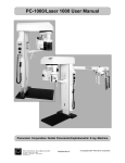
has been updated to reflect the variety of different operating
environments under which users run COADE software. The
new SYSCHK main screen is shown in the figure below:
Table Of Contents
PC Hardware for the Engineering User (Part 19) ...... 1
What’s New at COADE
TANK Enhancements ........................................... 2
CAESAR II Version 3.21 Released in July .......... 2
Seminar Schedules for 1995 .................................. 3
German Language Files Available for
CAESAR II ....................................................... 4
The major changes/enhancements to this program are:
•
A revised detection method for the DOS SHARE utility
is implemented. This is necessary because it is illegal to
load SHARE once Windows is loaded. Therefore
Windows always patched the standard detection method
to lie about the existence of SHARE. SYSCHK can now
detect if SHARE is loaded, even from a DOS box under
Windows.
•
The new SYSCHK checks to see if DOS is loaded in
high memory.
•
The new SYSCHK checks to see if Windows is loaded,
and if so what version is running.
Technology You Can Use
Caution When Moving COADE Programs ........... 4
Notes on the Density of Calcium Silicate
Insulation ........................................................... 4
Local Coordinate Systems - Revisited ................... 4
Fine Tuning & Sensitivity Studies – Added
Benefits of Piping System Analysis .................. 6
The CAESAR II Pulse Table Generator .............. 9
Commonly Asked CAESAR II Questions .......... 12
CAESAR II Specifications ................................. 13
TANK Specifications .......................................... 14
CodeCalc Specifications ..................................... 14
CAESAR II celebrates 10 years
of industry leadership
this December
PC Hardware & Systems for the
Engineering User (Part 19)
Summer 1994 brought about a new release of all COADE
software products. In addition to supporting a local ESL
from a new vendor, these releases also support a network
ESL. Additionally, the SYSCHK (system check) program
•
The new SYSCHK checks to see if a network redirector
is running.
•
The new SYSCHK also checks to see if disk caching or
disk compression have been implemented.
1
COADE Mechanical Engineering News
November, 1994
The main purpose of SYSCHK is to provide a concise
summary of the machine environment - as an aid to the
COADE support staff. The machine environment can be
altered by modifying the CONFIG.SYS and
AUTOEXEC.BAT files, used during system startup.
What are some of the “more important” items on the main
SYSCHK screen? First and foremost is the presence of a
math coprocessor. All COADE products require the math
chip (shown on the right side of the screen, near the middle).
This means that 486/SX processors can not be used by
COADE software. These chips have the math coprocessor
disabled!
The second most important item is the amount of low, free,
DOS RAM. The User’s Manual for each COADE program
specifies the amount of free RAM required to run the software.
Attempting to run the software with less than this amount
results in an abort condition. (A related item necessary for
CAESAR II is the amount of free extended memory. Version
3.21 of CAESAR II requires 2.3 Mbytes of free extended
memory to run the input processor.)
Another important item on the SYSCHK screen is the setting
of the environment variable (on the left side of the screen). If
the environment variable for the program is not set, you must
run out of the program installation directory, and the “switch
directory/drive” feature of the file manager is disabled.
Pathworks Network Users: A major incompatibility problem
between Pathworks and the CAESAR II graphics hardcopy
drivers has been resolved. Updated modules are available
from the CAESAR II file area of the COADE BBS. The
necessary changes are being distributed as "Patch B". The
file to download is B321_U.ZIP.
Some users have asked about the operation of COADE
software on Pentium processors.
COADE has tested all software products on a
Pentium/90 without any problems.
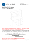
TANK Enhancements
Work is progressing for the version 1.2 of the TANK
program. One item added for this release will be the ability
to plot the interaction diagrams for the API-650 Appendix P
limiting nozzle loads. Nozzle loads are indicated on the plot
as an asterisk, easily showing whether the loads are within or
exceed the code allowables. An example plot is shown in the
figure below.
2
The most important item added for the next version will be
the ability to perform a roof design, according to the
procedures outlined in Brownell & Young. This will provide
the number and size of rafters, girders, and columns for
supported cone roofs. Other enhancements include:
additional input specification for anchor bolts, settlement
parameters, more nozzles, external nozzle loads and weight.
CAESAR II Version 3.21 Released in July
In late July, CAESAR II Version 3.21 began shipping to all
users current on the update/maintenance plan. Besides the
major enhancements (see box), there were several smaller
changes (many a direct result of user suggestions and requests)
aimed at increasing ease-of-use, which were not given as
much attention in the update documentation. These subtle
changes are discussed below.
Graphics File Viewer: Many times users find themselves
staring at a directory of job files wondering what is in each
file or which version of a particular job contains a certain
modification. Entering the input processor and plotting the
model is a slow and tedious process - when looking for a
specific job or modification. If the selected job is not the one
desired, the input must be exited, then another job selected,
and the input/plot procedure repeated.
To aid in this job file search, Version 3.21 incorporates a
graphics file viewer directly into the File Manager of the
Main Menu. From the job file list, the job currently selected
can be viewed by simply pressing [P]. The job is plotted
showing restraints, valves, rigids, and expansion joints. The
next keystroke returns control back to the File Manager
where another job file can be selected. The entire procedure
takes approximately three seconds.
COADE Mechanical Engineering News
Note that there are no graphics controls built into the viewer
distributed with Version 3.21. This decision was made to
keep the viewer program as small as possible, which reduces
the load time. Once the desired job is found, the input
processor should be used to access the other graphics functions.
(A full featured viewer was developed, but the load/display
time approaches six seconds - for this reason the small viewer
was released.)
Major 3.21 Enhancements
• Low RAM requirement reduced to 475K
• Input model size limited only by amount of extended
memory
• B31.5 piping code added
• UBC earthquake spectra added
• Direct network support and network ESL
Input Echo Report Selection: From either the static or
dynamic output menus, a user can request an input echo of the
current job. This report was automatically generated based
on what was in the input file. Many users requested additional
control over the input echo, to deactivate certain reports. As
a result, Version 3.21 incorporates into the Input Echo
module the same report selection menu found in the input
processor.
CAESAR II Tutorial: Included in the update notes for the
Version 3.21 release is a one hundred page tutorial. This
tutorial (Chapter 4 of the Applications Guide) covers model
building, static analysis, and interpretation of results.
Network Drive Access: The File Manager incorporated into
the Main Menu and both the static and dynamic output
processors has been enhanced to search out and subsequently
access all network drives. (Previous versions of the software
would access all drives up to the first nonexistent drive. This
caused non-contiguous network drives to be invisible to the
software.) Version 3.21 specifically searches for all drives
from A to Z, and maintains a list of valid drives discovered.
Note that the installation program (INSTALL) also
incorporates this enhancement, to facilitate installation on
network drives.
November, 1994
Seminar Schedules for 1995
Our seminar schedule for 1995 has been set. It appears
below. We will again have five piping analysis seminars and
two pressure vessel courses. These are our open attendence
courses held here in our training room. Other, in-house,
training can be held at any time, anywhere, by appointment.
The CAESAR II courses will be held here every other
month except for July. Our entire support staff pitches in as
instructors for these courses so you get to understand several
different approaches to system analysis. There is also ample
time to meet with other students during lunch and other
breaks to discuss common issues in engineering, analysis,
and construction.
One change for 1995 is the elimination of the three day
introductory course to pipe stress analysis. Even though the
people who attended the course saw the value in it,
participation was light. To bring new CAESAR II users up
to speed, we will offer an optional Monday evening session
to review and explain CAESAR II basics.
Class size is currently limited to 17 students and most classes
are fully booked. Sign up early to lock in your dates. We find
that this is an excellent opportunity for all engineers and
designers, both new and experienced users alike, to spend a
few days on the subject without interruption. Understanding
the concepts in modeling and analysis will produce better
design strategies, more efficient use of time, and greater
confidence in the results.
Piping Seminars in Houston, Texas
January 23-27
Statics & Dynamics
March 20-24
Statics & Dynamics
May 15-19
Statics & Dynamics
September 11-15
Statics & Dynamics
November 13-17
Statics & Dynamics
Pressure Vessel Seminars in Houston, Texas
Accounting: The Accounting Module has been completely
replaced for Version 3.21, to streamline the operation of the
system. The initial release of this module allowed the
generation of accounting reports to a disk file (C2ACCT.OUT)
only. At the request of several users, this module has been
modified to send the reports to the terminal screen or the
active printer. This new module is available from the BBS,
in the CAESAR II download area. The file name is
ACCOUNT.EXE.
February 6-8
October 16-18
3
COADE Mechanical Engineering News
German Language Files Available
for CAESAR II
As of November 1994, the language text files utilized by
CAESAR II have been translated into German. These new
language files provide German users the same presentation
abilities as has been available to Spanish and French users.
The German language files are available for download from
the COADE BBS, as GERMAN.ZIP in the CAESAR II file
area. This file has also been forwarded to the COADE dealer
in Germany.
For users running COADE software from a DOS
box under Windows/NT, ESL drivers are available
for download from the BBS.
The necessary file is WIN_NT.ZIP, located in the
“Miscellaneous” file area. This file contains drivers
and instruction files for all ESLs supported by
COADE software. These drivers will be part of
subsequent software releases.
Caution When Moving COADE Programs
Most users eventually have the need to move a software
program, either from one machine to another, or from one
disk drive to another. Up until the Summer 94 releases, this
was a rather simple affair for COADE products. However,
as of the Summer 94 releases, there are two new traits of
COADE software products that may hamper the simple
“copy from here to there” scenario.
First, the products are no longer managed by a .COM
program. The old .COM loader/manager has been replaced
by a more powerful .EXE loader/manager. What does this
mean to the user? By default, DOS looks for .COM files
before .EXE files. Therefore if one of the products is moved
to a location where DOS finds an old .COM before the new
.EXE, the program will not run. Instead, the user will receive
an error message that the Main Menu module could not be
loaded. (Using INSTALL instead of a COPY procedure
eliminates this problem, since INSTALL cleans up the
installation directory.)
This switch from a .COM to a .EXE can also cause the same
error to occur if more than one version of the software exists
on the computer. DOS will find and execute whichever
loader it finds first when it walks down the PATH. Users with
multiple versions of the same product, on the same machine,
must adjust the AUTOEXEC.BAT file to correctly run the
programs.
4
November, 1994
The second change in the Summer 94 releases is that all
products now reference a SYSTEM subdirectory (beneath
the installation directory) for certain data files, which may be
subject to alteration by the user. These files are now located
in SYSTEM to allow network installations the option of
“write protecting” the program directory. If the software is
moved, the SYSTEM subdirectory must be moved also in
order for the software to find the necessary data files.
Notes on Insulation Densities
(Calcium Silicate)
As most users know, CAESAR II allows the specification
of insulation density as an elemental property. The
CAESAR II help facility offers suggested values of
insulation density based on the type of insulation. If the
value of insulation density is not specified by the user,
CAESAR II will default to calcium silicate, and assume a
density of 11 lb/ft3.
Recently, a user pointed out that ASTM-533 states that the
density of calcium silicate insulation is 15 lb/ft3. This
statement is in fact true. However, several other references
were checked, and the following density values for calcium
silicate obtained.
Source
Grinnell Catalog
The Piping Guide
Intro to Pipe Stress Analysis
Density
11 lb/ft3
11 lb/ft3
11 lb/ft3
Users should be aware of the default data used for engineering
computations, its origin, and other possible values.
Local Coordinate Systems - Revisited
By Richard Ay
The December 1992 issue of Mechanical Engineering News
contains an article discussing the “Global” versus “Local”
coordinate systems implemented in CAESAR II. This
article explains what each coordinate system represents and
how they can be determined. Many users have requested
additional information on this subject, especially for bends
and skewed sections of a piping model. This article is
intended to provide this information.
The figure below shows a small piping system with the local
coordinate system for each elbow sketched near the element.
The local element coordinate system for an elbow can be
determined as follows: local “x” is directed along the incoming
COADE Mechanical Engineering News
November, 1994
tangent, in the From-To direction; local “z” points towards
the center of the circle described by the bend; local “y” can
be found by applying the right hand rule.
Note that the figure above and the figures from the 12/92
article all represent systems aligned with the Global coordinate
system. How can the system forces and moments for skewed
piping be resolved? The figure below shows a portion of a
line which terminates at a vessel nozzle. The pipe running
into the nozzle makes an angle of 150 degrees with the Global
“X” axis. (Note that the pipe nodes are from 190 to 200,
which defines the direction of the Local “x” axis. The angle
from the Global “X” axis to the Local “x” axis is 150
degrees.) We need to know the loads imposed on the nozzle
for a WRC-107 analysis, which means radial, circumferential,
and longitudinal directions. (If the pipe element had been
aligned with the Global “X” or “Z” directions, it would be a
simple matter to obtain the forces and moments from the
restraint report. However, for a skewed system, the forces
and moments must be obtained from the element force/
moment report - with a change in sign.)
The figure below shows both the “Global” and “Local”
coordinate systems for the pipe element 190-200. Below the
figure are the Global and Local Force reports for this element
for the Operating case, and the Restraint report for node 200.
RESTRAINT REPORT, Loads on Restraints
CASE 3 (OPE) W+T1+P1+FOR
NODE
200
—— Forces(lb.) ——
FX
FY
FZ
-302.
-234.
564.
— Moments(ft.lb.) —
MX
MY
MZ
TYPE
57.
Rigid ANC
-6352.
-3.
FORCE/STRESS REPORT, Forces on Elements
CASE 3 (OPE) W+T1+P1+FOR
DATA
POINT
190
200
——Forces(lb.)——
FX
FY
FZ
-302
302
-87
564
233 -564
—Moments(ft.lb.)—
MX
MY
MZ
-345 -3153
-56 6351
693
3
LOCAL FORCE REPORT, Forces on Elements
CASE 3 (OPE) W+T1+P1+FOR
DATA
POINT
190
200
——Forces(lb.)——
fy
fz
fx
-20.
20.
-640.
640.
88.
-234.
mx
-47.5
47.5
—Moments(ft.lb.)—
my
mz
-773.2
-31.0
3153.5
-6351.9
5
COADE Mechanical Engineering News
The radial force needed for the WRC-107 analysis is simply
the “negative” of the local “fx” at node 200, or -20.0 pounds.
The circumferential moment is the “negative” of the local
“mz” at node 200, or 6351.9 foot-pounds. The longitudinal
moment is the negative of the local “my” at node 200, or 31.0
foot-pounds.
These Local forces and moments can be related to the Global
forces and moments at node 200 by applying the “coordinate
system rotation” matrix. This transformation matrix (for a
two-dimensional system) is shown below.
{f }= [ M] {F}
fx cos θθθθ-sin θθθθ FX
=
∗
fz sin θθθθ+ cos θθθθ FZ
For this system, the angle theta is 150 degrees. This results
in the following matrix equation, based on the forces and
moments from the “Global Force/Moment” report.
fx = (-.866)(302) - (.5)(-564) = 20.5
fy = (.5)(302) + (-.866)(-564) = 639.4
mx = (-.866)(-57) - (.5)(3) = 47.9
my = (.5)(-57) + (.866)(3) = -31.1
Note that for this system, the Global “Y” direction corresponds
to the Local “z” direction, and the Global “MY” corresponds
to the Local “mz”.
The resulting “local” forces and moments agree with those
reported in the “Local Force/Moment” report. These forces
and moments represent the loads acting on the end of the pipe
element. To use these values in the WRC-107 analysis, the
signs must be reversed, since the forces on the vessel are
needed.
More information on local-global transformations can be
found in most graphics texts, and in texts on matrix solutions
to engineering problems.
The COADE BBS has recently been upgraded to the
latest version of PCBOARD. Suggestions
from the users of the BBS are welcome.
Users desiring additional information about using
this BBS can download the file BBS_INFO.ZIP
from the “Information” file area.
6
November, 1994
Fine Tuning & Sensitivity Studies –
Added Benefits of Piping System Analysis
By David Diehl
With today’s software-based analysis tools so quick and
convenient, their application has been expanded to include
“what-if” analysis. For example, “what-if” a support is
moved down the line a few feet or “what-if” the spared pump
is not heat traced. One change of the input data and a few
more seconds of analysis will allow the engineer to evaluate
the reliability of the system under variations in installation
and under unexpected operating conditions. Within minutes,
and without paper, the results from a base model’s analysis
can be compared to those of a modified model.
When only small, simple model changes are made in each
design iteration, these modifications could serve two
purposes. First, if the model is accurate, the modification can
push the design closer to the desired value. This will be
called fine tuning the design. Second, the modification is
made only to test the impact of the change in the results. This
will be called a sensitivity study. Both fine tuning the design
and the sensitivity study are a natural outgrowth of computer
simulation.
Fine tuning has a specific goal in mind. For example, if pump
loads must be reduced then intelligent changes are made to
the model and the results are examined to see if that goal is
approached. Of course, fine tuning is only valid if the model
itself is “fine” or detailed in the first place. The sensitivity
study is more of a discovery process. The model is “tweaked”
to see how sensitive the results are to the change. For
example, if pump loads are low in a model where all rack
piping supports are modeled as “rigid Y restraints” (with a
stiffness of 106 lbf./in.) but pump loads are high when these
rack supports are modeled with structural steel elements, the
model is sensitive to the support stiffness and accurate
restraint stiffnesses are then important in this design. The
figure below exemplifies this process. The three lines
signify the limits on typical pump/piping systems. The area
bounded by these limits indicates safe and reliable operation
while results falling outside are not acceptable. If a user is
uncertain about some aspect of the model, a second job is
analyzed which changes that aspect. If the results move from
#1 to #2, the uncertainty has no great impact. If, however, the
results move from #1 to #3, than the user should take the time
to research the issue and build a more accurate model. This
sort of investigation was not feasible with earlier analysis
methods due to the inherent inaccuracies or because of the
large commitment in time.
COADE Mechanical Engineering News
November, 1994
An Example
Figure 1
This sensitivity study serves several purposes. First of all it
can identify critical design parameters in the model analysis
and in the actual layout. A sensitivity study is used to find
significant design modifications and study their impact on
the piping system. Another advantage to this approach is the
investigation into the variability between the “as designed”
system and “as built” system. Troubleshooting possible
variations in installation requires anticipation of possible
differences but, when uncovered, these critical construction
guidelines can be established before the line is built rather
than when the line is shut down for repair. Finally, this sort of
study can actually simplify the analysis by revealing model
details which prove to have no impact on results; a
simplification that saves modeling time and effort and
improves comprehension. Again, this sort of analysis
technique does not replace experience but works well with
design experience to develop a feasible and reliable layout.
In many ways, a sensitivity study is a cost effective check on
piping systems with their tight load restrictions around rotating
equipment.
Figure 2
To illustrate the concepts promoted here and to provide an
example of this sensitivity study a pump system will be
analyzed using CAESAR II. The system shown in Figure 2
illustrates the piping around the 10 inch suction and 8 inch
discharge lines. Figure 3 shows the entire 26 element system
with node numbers and several of the supports. The suction
side runs from node 5 to node 70, the pump is constructed of
rigid elements 70 to 90, and the discharge pipe carries on
from node 90 to node 145. The boundary conditions are set
at nodes 5 and 145 with a known operating position of node
5 and an immovable point at 145. With the drawing prepared
with all the required data, an experienced user can produce
a first pass analysis in under 15 minutes. The program selects
the spring for installation at node 125 (in this case from the
Grinnell catalog) and then calculates the system loads and
displacements for the operating and installed conditions and
the B31.3 sustained and expansion stresses. The pipe stresses
are well within the B31.3 limits.
7
COADE Mechanical Engineering News
November, 1994
API Standard 610 1989 7th Edition
File
Date
Time
User Entered Description :
: RELY
: SEP 1,1994
: 11:42 am
AS DESIGNED
Suction Nozzle
Discharge Nozzle
Node #
70
90
Orientation
End
Top
Table 2 Allowable ( ratio )
Nominal Diameter
10
8
=
2
Pump Axis is in the “X” direction.
Suction
Table 2
Values
Force & Moment
Ratios
Status
X Distance
Y Distance
Z Distance
=
=
=
10.5
.0
.0
in.
in.
in.
X Force
Y Force
Z Force
= -1522.0
= -1931.0
=
-674.0
lb.
lb.
lb.
1500
1000
1200
1.01
1.93
.56
Passed
Passed
Passed
X Moment
Y Moment
Z Moment
=
4270.0
= -5152.0
=
3110.0
ft.lb.
ft.lb.
ft.lb.
3700
2800
1800
1.15
1.84
1.73
Passed
Passed
Passed
Figure 3
Discharge
The calculated pump nozzle loads are compared to the limits
defined in API Standard 610. The simple check compares
the component loads on the nozzle to values based on nozzle
size and orientation. If the nozzle loads are below these limits
(specified in Table 2 of the standard), then the pump alignment
is assured. A second test is available for pumps if the Table
2 limits are exceeded. This secondary check is defined in
Appendix F of the standard. Appendix F has three checks:
Table 2
Values
F.1.2.2 - the resultant forces and moments on each nozzle,
and
F.1.2.3 - the resultant forces and moments and the moment
about the local Z axis of all loads resolved to the
center of the pump
The example here generates pump loads that exceed the API
610 Table 2 limits. It is necessary, then, to examine the
Appendix F limits defined in that standard. The
CAESAR II API 610 processor collects the definition of the
pump along with the nozzle loads to check the Appendix F
criteria. The API 610 report (shown in Figure 4) confirms
that the 10 inch end suction nozzle and the 8 inch top
discharge nozzle meet the Appendix F criteria; the pump is
OK.
8
Status
X Distance
Y Distance
Z Distance
=
=
=
.0
15.0
12.3
in.
in.
in.
X Force
Y Force
Z Force
=
-313.0
= -1499.0
=
279.0
lb.
lb.
lb.
850
1100
700
.37
1.36
.40
Passed
Passed
Passed
X Moment
Y Moment
Z Moment
=
3596.0
= -2099.0
=
2526.0
ft.lb.2600
ft.lb.1900
ft.lb.1300
1.38
1.10
1.94
Passed
Passed
Passed
Check of Condition F.1.2.2
F.1.2.1 - the component loads on each nozzle (which can be
as large as twice the Table 2 limits),
Force & Moment
Ratios
Requirement
(FRSa/1.5FRSt2) + (MRSa/1.5MRSt2) = 1.756
(FRDa/1.5FRDt2) + (MRDa/1.5MRDt2) = 1.593
Check of Condition F.1.2.3
Status
1.5 ( FRSt2 + FRDt2 )
2.0 ( MZSt2 + MZDt2 )
1.5 ( MRSt2 + MRDt2 )
= 5640. > 3910.
= 6200. > 4338.
= 12750. > 12748.
< or =
< or =
Status
2.00 Passed
2.00 Passed
Requirement
(FRCa)
(MZCa)
(MRCa)
Passed
Passed
Passed
Overall Pump Status Passed
Figure 4
With the calculated pump loads so close to their limits it is
wise to take a much closer look at the model to confirm it is
correct. Any questionable input items could be “tweaked” to
examine their impact on the results. If the results do not
suffer, no additional investigation into these model details is
necessary.
If the system is built as it was designed the pump should
operate without difficulty. To illustrate an additional benefit
of this analysis, four variations on this design will be used to
determine how sensitive the pump is to the hanger load and
position. As it is initially designed, the hanger (at node 125)
is placed 7 feet from the discharge riser. It is a Grinnell
COADE Mechanical Engineering News
Figure B-286 (mid range) spring with a spring rate of 260 lbf./
in. The spring’s load is set to 1200 lbf. when the system is in
operation. Since the spring moves 1/3 inch to its operating
position, the installation load on the spring is set to 1286 lbf.
Four additional analyses will be made to test the significance
of common installation variations. All four involve the spring
and are very simple to run through the program. The changes
are:
•
Set the spring load to reach only 70% of the operating
load,
•
Set the spring so that the spring load is 130% the design
value,
•
Move the spring towards the discharge riser by 3.5 feet,
and
•
Move the spring 3.5 feet away from the discharge riser.
In each case the suction loads on the pump are the same. The
pump discharge loads (in pounds and foot-pounds) for each
variation are shown in Table 1 below. The final column
(% of allowable) lists the maximum ratio of the Appendix F
criteria.
Case
FX
FY
FZ
MX
MY
MZ
% of allowable
1 - light load
2 - heavy load
3 - closer
4 - farther
-315
-312
-313
-316
-1745
-1252
-1318
-1696
279
278
278
281
3620
3571
3619
3592
-2093
-2105
-2084
-2118
2172
2882
2166
2562
100.74
111.00
98.01
101.39
Table 1
Only one of these variations — moving the spring closer to
the riser — passes the API 610 check; the loads here are much
better than the original design. The other three cases fail for
the following reasons:
Case 1 - The moments resolved at the pump’s base point
exceed the allowable limit (Condition F.1.2.3),
Case 2 - The bending moment about the Z axis at the pump
discharge nozzle exceeds the two times the Table 2
value, and
Case 4 - The moments resolved at the pump’s base point
exceed the allowable limit.
Again, why were these analyses made? The analysis of the
original layout showed that the pump was very close to its
maximum rated loads. The model was first examined to
determine whether or not modeling shortcuts might have
produced low values for these loads. This initial review
November, 1994
could have indicated that model modification – “fine tuning”
– was necessary. But here the model looked fine so the
model was manipulated in the second fashion — a “sensitivity
study” was made. This sensitivity study did not focus on
variations in design layout but instead on variations on the
hanger installation. The study clearly illustrates that the
layout is sensitive to the spring; the spring load and position
must be properly set for reliable pump operation. It is
noteworthy that the spring, which in so many cases is used to
improve system loads, can also harm the design. Man time
for the four analyses in this study is minimal, about ten
minutes, but the benefits may be great. Not all systems
require this sort of study, but here, where the pump loads are
very close to their limits, such an examination plus a close
review of the model definition is warranted. If these pump
loads are not reduced, it would be wise to give close attention
to this pump at startup.
This sort of formal analysis can confirm a good piping design
and can assist the engineer in redesigning the piping system
when it is required. When used as a tool for sensitivity
studies, piping analysis software can indicate critical
installation parameters so that safe and reliable operation is
ensured.
The CAESAR II Pulse Table Generator
By Thomas Van Laan and Richard Ay
The Force Spectrum solutions offered by CAESAR II (for
simulation of relief valve, water hammer, slug flow, etc.) use
a frequency domain model based on a Dynamic Load Factor
(DLF) vs. natural frequency response spectrum. Dynamic
Load Factor is defined as the ratio of the system response
(i.e., deflection, force, stress, restraint load) during dynamic
application of a load to the system response which would
have resulted from the static application of the same load.
The DLF response spectrum for a given load is generated by
solving the dynamic equation of motion for a single degree
of freedom system:
Ma(t) + Cv(t) + Kx(t) = F(t)
Where:
M
a(t)
C
v(t)
K
x(t)
F(t)
=
=
=
=
=
=
=
mass of system, slug
acceleration of system (as a function of time), in/sec2
damping of system, slug/sec or lb-sec/in
velocity of system (as a function of time), in/sec
stiffness of system, lb/in
displacement of system (as a function of time), in
applied force (as a function of time), lb
9
COADE Mechanical Engineering News
For an idealized system, where the system damping is near
zero, and the loading takes the form of an instantaneously
applied constant force of infinite duration, the system
displacement solution is:
x(t) = (F/K) (1-cos ωt)
Where:
November, 1994
natural period of the system. (For an instantaneous rise time,
and an infinite load duration, the ratios to all natural periods
are the same, which explains why the DLF was constant for
all frequencies in the example discussed above). A review
of the textbook Introduction to Structural Dynamics, by
John M. Biggs, shows several plots of maximum DLF curves
as a function of the ratio of load duration to system natural
period.
x(t) = system displacement (as a function of time), in
F = magnitude of applied force, lb
ω = system angular natural frequency, rad/sec
= (K/M)½
t
= time, sec
Since the maximum static deflection of the system under load
F is calculated as F/K, the Dynamic Load Factor (or the ratio
of the dynamic to static response) is therefore (1 - cos ωt).
This DLF varies in magnitude from a value of zero to a value
of 2.0, where the maximum and minimum values fluctuate
along the time axis with the natural period (the engineer is, of
course, most interested in the maximum value of the DLF).
The response spectrum for this load is generated by plotting
the maximum DLF that occurs throughout the load duration
(2.0) vs. the natural frequency ω. Obviously, ω drops out of
the equation, so the DLF response spectrum for an
instantaneously applied constant load of infinite duration is
a flat value of 2.0:
2
0
omega
Once the Dynamic Load Factor is known, a static analysis of
the system (or of each mode of vibration, when considering
multiple degree-of-freedom systems) can be done, with the
static results then being multiplied by the DLF to yield the
dynamic results. Note that the DLF is a non-dimensional
value that is independent of the applied load.
Expanding this discussion to loads of different shapes and
durations allows the application of a force spectrum solution
to impulse loads of different types (technically, an impulse is
defined as the area under the force-time profile). The
dynamic response of a system to an impulse load is dependent
upon the ratios of the load duration and rise/fall rate to the
10
How is this information useful to the pipe stress engineer
who has a specific dynamic problem to solve? Usually, the
shape of the pulse load profile is trapezoidal, with the
duration of each segment known. For example, for a relief
valve load, the segments of the trapezoid consist of the load
rise (with a duration equal to the opening time of the valve),
the relatively constant jet load (with a duration equal to the
time required to vent the excess mass from the system), and
the load fall (with a duration equal to the closing time of the
valve). This type of load can be converted to a response
spectrum by solving the dynamic equation of motion through
each of the load segments, dividing the maximum
displacement throughout by the static displacement under
the maximum magnitude of the load, and then plotting the
result vs. natural frequency.
COADE Mechanical Engineering News
November, 1994
According to the textbook Structural Dynamics (Theory
and Computation), by Mario Paz, the displacements of a
system due to any arbitrary load can be calculated through the
application of Duhamel’s integral, as shown below:
X( t ) = X0 cos ωωωt +
2.0
1.8
1.6
υυυ0
1 t
sin ω
ω
ωt +
F( τττ) sin ω
ω
ω t - τττ d τττ
ω
ω
ω
ω
ω0
Mω
( )
∫
F1
tr
1.4
Where:
1.2
t
τ
= time for which displacement is solved, sec
= time at which force is applied, sec
1.0
0.0
When the arbitrary load can be broken into discrete, linearized
segments, the force function can be fairly easily integrated
using Simpson’s rule, permitting the solution of the system
displacements at any point throughout the duration of the
load.
CAESAR II provides the user with a Pulse Table/DLF
Spectrum Generator, which performs the automatic
integration of Duhamel’s integral. This module takes a user
supplied, segmented pulse, and creates the appropriate
equation for each segment. Displacements are calculated at
each terminus of the segment, and the equation is differentiated
in order to locate any displacement minima or maxima
ocurring within the interior of the segment (this assures that
the maximum displacement is found, without using a hit-ormiss approach). The absolute maximum dynamic
displacement is then selected from the largest of the segmental
values, and the DLF calculated from that. This process is
repeated for the number of natural frequencies specified by
the user, which, when plotted, create the response spectrum.
1.0
2.0
3.0
4.0
tr/T
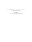
The ASME B31.1 Power Piping Code, in Section 3.5.1.3 of
Appendix II (Nonmandatory Rules for the Design of
Safety Valve Installations), presents a discussion on
dynamic load factors, including a DLF curve, adapted from
the Biggs text. Here, the Code uses to (the opening time of
the relief valve) to represent the rise time of the loading. The
figure below demonstrates how the ASME Code curve,
which is based upon an infinite load duration, envelopes the
DLF curves generated by CAESAR II for various finite
load durations.
Comparison of Dynamic Load Factors
2.0
1.8
1.6 Long Duration
1.4
1.2
1.0
0.8
0.6
0.4
Short Duration
0.2
0.0
0.1
Response spectra for the same load profiles as shown in the
theoretical plots above have been generated using the
CAESAR II Pulse Table/DLF Spectrum Generator, and
are shown below, demonstrating the accuracy of
CAESAR II’s algorithm:
ASME Curve
1.0
10.0
t0/ T
In general one can reach the following conclusions about
Dynamic Load Factors and impulse loading:
2.0
•
The magnitude and shape of the DLF curve is
independent of the magnitude of the applied force, but
dependent on the shape of the normalized load profile.
Therefore the CAESAR II user may specify the actual
load, or a normalized value of 1.0 as the pulse magnitude.
•
If the rise time is much greater than the natural period of
the system, the system response approaches the static
response to the applied load - the dynamic effects (and
thus the DLF) are negligible.
1.6
1.2
F1
0.8
td
0.4
0.0
0.0
0.1
1.0
10.0
td/T
11
COADE Mechanical Engineering News
•
•
The shorter the rise time of the load profile is, the greater
the DLF will be. If the rise time (for a load of infinite
duration) is less than approximately one quarter of the
natural period, the response approximates that for an
instantaneously applied load — i.e., the DLF is 2.0.
As the duration of the load increases, peak dynamic
response (higher DLFs) will shift toward the systems
with longer natural periods (smaller natural frequencies).
Commonly Asked CAESAR II Questions
By Tim Curington
The following begins a Question & Answer series that will be
continued in subsequent newsletters. In addition, these and
other Q & A entries can be found in the subsequent editions
of the program documentation, and on the COADE BBS.
The series is intended to provide an additional reference
source from which to obtain answers to
CAESAR II questions.
1) Why are the allowable stress values zero for the operating
condition?
Operating stresses are not considered by the Power and
Petrochemical Codes. Therefore, when reviewing operating
stresses, the user will first be confronted by the message that
states ‘NO CODE STRESS CHECK PROCESSED’, and
then the user will notice that all of the allowable stress values
are set to zero. This is not the result of incorrect data input,
but rather a result of whether the individual Code being used
reviews operating stresses or not.
2) What is the difference in the expansion case D1 - D2 and
just running a T case?
The expansion case is described in the Codes as the differential
between extreme conditions of the piping system (i.e.,
normally cold and operating cases). If, for example, the
operating load case is W + P + T and the sustained (cold) load
case is W + P, by subtracting the sustained loads from the
operating loads we are left with the temperature effects T. So
are the results acquired from the difference of the two loads
the same as just running a T case? In the event of a
completely linear system the answer would be yes. If,
however, there are any nonlinear effects in the system (friction,
gaps, single directional supports, etc.) these two results
could vary.
In the latest addenda to B31.3, Interpretation 12-06
acknowledges that the maximum and minimum operating
temperatures should be considered as one of the "ranges" in
computing the expansion case. This is in agreement with the
12
November, 1994
article "Expansion Case For Temperatures Below Ambient",
published in Mechanical Engineering News, May 1993.
By examining a pipe resting on a pipe rack, this variance can
be seen. In the sustained (cold) condition, the pipe is resting
on the rack, and there is a deadweight load imposed on the
rack. In order for the pipe to move off of the rack, the forces
due to expansion must first overcome the deadweight load.
Therefore, the loading on the pipe will be the difference
between the deadweight load and the forces due to the
expansion of the pipe. If instead of reviewing the difference,
the user looked at the temperature case only, the deadweight
effects would be ignored. In order to adhere to one code’s
definition of secondary loadings ( loadings due to expansion,
weight stress variation, differential settlement, movements
in the supports, etc. ) these deadweight effects must be
considered.
3) I have entered wind/uniform loads in the job, but my
results have not changed?
NO OCCASIONAL LOADS ARE INCLUDED IN THE
CAESAR II RECOMMENDED LOAD CASES. Although
COADE has suggested guidelines (Chapter 5 of the User’s
Manual) on setting up load cases for occasional loads,
CAESAR II does not recommend them automatically. It is
the user’s responsibility to edit the recommended, or existing,
load cases in order to include these occasional effects in the
analysis. Additionally, if wind has been included in the
input, the user must define the wind loading. Upon entering
the static processor, the user will first edit the wind loading
data, and then edit the load cases to include the wind effects.
4) How can I get CAESAR II to create larger printed
plots?
The size of the CAESAR II printed plots is determined by
your graphics resolution. LaserJet printer resolution is
typically 100 dots/inch in the horizontal direction and 75
dots/inch in the vertical direction. Knowing this, you can
determine the size of the expected plot based on your
individual graphics resolution. For example, a Color Graphics
Adapter (CGA) has a resolution of 640 X 200 dots. Therefore,
a horizontal plot would yield 6.4 inches in the horizontal by
2 inches in the vertical (based on the horizontal printer
resolution of 100 dots/inch). Similarly, a vertical plot would
yield 8.53 X 2.67 inches (based on the vertical printer
resolution of 75 dots/inch). The largest available plot is
going to be with VGA graphics (640 X 480 resolution) in the
vertical direction, which yields a plot 8.53 inches X 6.4
inches.
COADE Mechanical Engineering News
CAESAR II Specifications
Listed below are those bugs/errors/omissions in the
CAESAR II program that have been identified since the last
newsletter. These items are listed in two classes.
Class 1 errors are problems or anomalies that might lead to
the generation of erroneous results. Class 2 errors are general
problems that may result in confusion or an abort condition,
but do not cause erroneous results.
Class 1
1) Hanger Design Modules: An error has been discovered
in the computation of the “Actual Installed Load” on
Variable Spring Hangers when more than one hanger is
specified at the location. This error was an output error
only and involved the application of the spring rate of the
total installation to each individual spring. This did not
cause an error in spring selection, calculation of hot or
cold load, or subsequent load case results. This error
exists in all versions of CAESAR II prior to Version
3.21, and was corrected in Version 3.21a, which was
sent to all current users.
2) Refractory Lined Pipe: An oversight was discovered in
the element generator when generating the mass matrix
for dynamic jobs. The presence of refractory lining was
not considered.
This error exists in Versions 3.19, 3.20, and 3.21, and is
corrected in Version 3.21a.
Class 2
1) Analysis Setup Module: A file management error has
been discovered in the setup of the wind loading data for
“structural only” jobs. For these jobs, if an attempt was
made to adjust the ASCE #7 wind data, the program
aborted back to DOS. This error exists only in Versions
3.19 and 3.20. This error was corrected for the Version
3.21 release.
2) WRC-107 Module: A units conversion problem was
discovered in the WRC-107 module which was activated
if the user made an input error. When the program
detected the input error, it returned control to the input
routine, by passing the units conversion step. This error
is only apparent for non-English operation. This error,
corrected for Version 3.21, is in all other 3.x versions of
the program.
November, 1994
3) Pen Plot Module: A plotting error was discovered in the
Pen Plot module which caused all elements of the model
to be plotted as expansion joints - when the job included
thermal bowing. This error exists in Versions 3.19,
3.20, and 3.21. This error also exists in the Animation
Module in Versions 3.19 and 3.20. This was corrected
in 3.21a.
4) Static Output Module: An error has been discovered in
the static output module which could cause the restraint/
hanger symbol plotting to put the symbols at incorrect
locations. This problem only occurred if the “restraint
summary” report was previously requested, resulting in
a restraint nodal sort. This plotting error exists in
Versions 3.19, 3.20, and 3.21. This was corrected in
3.21a.
5) Graphics File Saves: A compiler conversion problem
was discovered which prevents “appending” to graphics
image files. This problem exists in Versions 3.20 and
3.21 in the following modules: piping input, structural
input, dynamic animation, static output. This was
corrected in 3.21a.
6) Documentation, Technical Reference Manual: On page
3-27 of this document, reference is made to using the
[Alt] key to plot node numbers with hangers, supports,
anchors, and nozzles. This is an error, the proper key to
use is [Shift].
On page 6-20, the Expansion case is defined as D1-D2.
This is incorrect, it should be D3-D4.
7) Piping Error Checker: Two errors have been discovered
in the piping error check module. The first error occurs
when the “INCLUDE” feature is used with the “N” (no)
option, and the second intersection field of the SIF
auxiliary field is used. The node number increment is
not applied to this second intersection node, resulting in
a fatal error. This error exists in all CAESAR II 3.x
versions.
The second error limits the number of intersections to
200. This limit should have been removed in Version
3.21. This was corrected in 3.21a.
8) Piping Input Module: An error has been discovered in
the input module when attempting to use Stainless Steel
pipe schedules. The addition of the half-pipe sizes (in
Version 3.21) caused the access routine to overlook the
stainless thicknesses, resulting in an error notification
during input. This was corrected in 3.21a.
13
COADE Mechanical Engineering News
9) Piping Input Module: A change has been made in the
ordering of the bend node numbers during the node
number increment. Versions prior to 3.21A incremented
the auxiliary bend nodes backwards, causing the new
nodes to be ordered incorrectly. This was corrected in
3.21a..
10) Input Listing Module: A memory management error has
been discovered Version 3.21 in the Input Listing Module.
This error causes some input data to be omitted from the
listing report, for jobs that exceed roughly 1000 elements.
This was corrected in 3.21a.
11) Documentation, Applications Guide: Pages 3-93 through
3-96 should have been reprinted for the 3.21 update.
This is necessary since the echo of two elements moved
from 3-92 to 3-93.
TANK Specifications
Listed below are those bugs/errors/omissions in the TANK
program that have been identified since the last newsletter.
These items are listed in two classes. Class 1 errors are
problems or anomalies that might lead to the generation of
erroneous results. Class 2 errors are general problems that
may result in confusion or an abort condition, but do not
cause erroneous results.
November, 1994
to those for the first nozzle. This error exists in both
Version 1.00 and 1.10 of TANK. This problem was
corrected in Version 1.10C and was shipped to all users.
Class 2
1) Input Module: An error has been discovered in the
Version 1.10 input module regarding the automatic
specification of elastic modulus and expansion
coefficient for the Appendix P nozzles. The data
provided is correct, however for nozzles 2 through 5 this
information is placed in the wrong input cells. This
error is obvious to the user when specifying the remaining
nozzle data. This problem is corrected in Version
1.10C.
2) Output Generation Module: Several conversion errors
were discovered in the output preprocessor which
affected the display of “user input”. The values of:
design temperature, bottom plate yield stress and bottom
plate thickness were not converted from the English
system properly. This error exists in Versions 1.00 and
1.10 of TANK and is corrected in Version 1.10C.
3) Output Generation Module: An error exists in Version
1.10 which prevents the nozzle input text labels from
being associated with the proper input data. This error
produces incorrect input listings. This problem is
corrected in Version 1.10C.
Class 1
1) Appendix E Seismic Computations: An error has been
discovered in the Appendix E seismic calculations
regarding the usage of the “percentage of roof weight
supported by the shell”. This user specified percentage
value (entered on the Roof Details Spreadsheet) should
have been divided by 100.
This error exists in Versions 1.00 and 1.10 of TANK.
The error was corrected and Version 1.10A was shipped
to all users.
CodeCalc Specifications
Listed below are those bugs/errors/omissions in the CodeCalc
program that have been identified since the last newsletter.
These items are listed in two classes. Class 1 errors are
problems or anomalies that might lead to the generation of
erroneous results. Class 2 errors are general problems that
may result in confusion or an abort condition, but do not
cause erroneous results.
Class 1
2) Appendix E Seismic Computations: An error has been
discovered in the Appendix E seismic calculations in the
determination of the required anchor bolt size. The bolts
were oversized by a factor of approximately SQRT(pi/
4). This error exists in Version 1.10, and was corrected
in Version 1.10C and shipped to all users.
3) Appendix P Nozzle Computations: A data management
error prevented the computation of nozzle stiffnesses
and limiting loads for any nozzles after the first one
specified. The results for subsequent nozzles are identical
14
1) The UCS-66.1 MDMT reduction was off for vessels
whose required thicknesses were between .4 and .5 of
the actual thickness. This problem was corrected in
Version 5.30A and was shipped to all users.
2) The piping materials used by the Pipe&Pad program
were updated to the latest edition of the B31.1 piping
Code. These were updated in 5.30A.
COADE Mechanical Engineering News
November, 1994
3) The tubeside corrosion allowance was not being added
to the flange thickness in the Floating Heat program.
This was corrected in 5.30A.
4) The allowable stresses in the summary of shellside
pressure for primary type stresses were modified in the
Thick Joint program. The computation for the factor
theta B at X=YB was also corrected. These were
corrected in 5.30A.
Class 2
1) A file sharing conflict was discovered which kept more
than one user from using the input processor at the same
time on Pathworks Networks. This problem was resolved
in 5.30A.
2) The occasional load factor was not being used for
computations involving angles in the Leg&Lug program.
This was corrected in 5.30A.
15
COADE Mechanical Engineering News
November, 1994
Compuserve Access to COADE
Due to the increased usage of our Bulletin Board (BBS), and the needs of our overseas users, COADE is establishing
both a forum and a mail address on Compuserve. This service will be available to upload or download files, or to
post general questions and answers. (Users will need to have their own Compuserve account to take advantage of
this service. In the U.S., this costs $8.95 per month plus any service charges.) Most users will be able to access
Compuserve via a local telephone call.
The COADE mail address is 73073,362.
COADE Engineering Software
12777 Jones Rd. Suite 480, Houston, Texas 77070 Tel: 713-890-4566 Fax: 713-890-3301 BBS: 713-890-7286
16