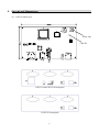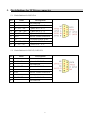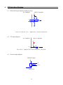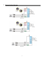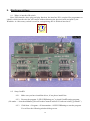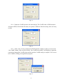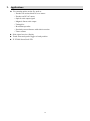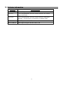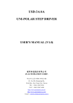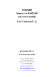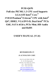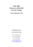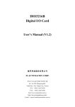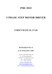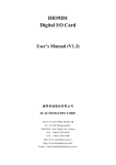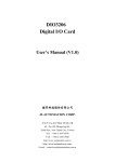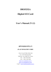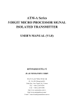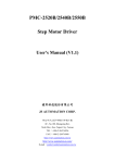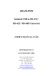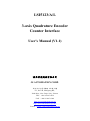
1
LSI5123/A/L 3-axis Quadrature Encoder Counter Interface User's Manual (V1.1) 健昇科技股份有限公司 JS AUTOMATION CORP. 新北市汐止區中興路 100 號 6 樓 6F., No.100, Zhongxing Rd., Xizhi Dist., New Taipei City, Taiwan TEL:+886-2-2647-6936 FAX:+886-2-2647-6940 http://www.automation.com.tw http://www.automation-js.com/ E-mail:[email protected] Correction record Version Record 1.0 firmware version 1.0 up 1.1 Update quadrature input frequency at x1, x2, x4 1 Contents 1. Forward ................................................................................................................................................ 4 2. Features ................................................................................................................................................ 5 2.1 Main card .................................................................................................................................... 5 Specifications ....................................................................................................................................... 6 3.1 LSI5123 Main card ..................................................................................................................... 6 Layout and dimensions ........................................................................................................................ 8 4.1 LSI5123 Main card ..................................................................................................................... 8 Pin definitions for 9P D-type connector .............................................................................................. 9 5.1 Pin definitions for LSI5123A ...................................................................................................... 9 5.2 Pin definitions for LSI5123, LSI5123L ...................................................................................... 9 I/O Interface diagram ......................................................................................................................... 10 3. 4. 5. 6. 6.1 Differential input diagram (LSI5123A only) ............................................................................ 10 6.2 TTL input diagram .................................................................................................................... 10 6.3 General output diagram ............................................................................................................. 10 7. External wiring diagram .................................................................................................................... 11 8. Hardware settings .............................................................................................................................. 12 8.1 Where is interface ID switch ..................................................................................................... 12 8.2 Setup CardID............................................................................................................................. 12 9. Applications ....................................................................................................................................... 14 10. Ordering information ........................................................................................................................ 15 2 Notes on hardware installation Please register as user’s club member to download the “Step_by_step_installation_of_USB_control_interface” document from http://automation.com.tw 3 1. Forward Thank you for your selection of PCI bus LSI5123 quadrature encoder/linear scale interface. In the field of automation, encoder and linear scale as feedback or measuring element is common used in the microprocessor control system. But for the versatile application in PC based control, only a few selections you can make. We integrate 3 axes (channels) in one USB interface with the state of the art technology of FPGA chip and experienced functions such as external probe triggered latch. Low cost and high performance makes this USB interface a better choice to use in the servo control feedback, 3D measuring system and other applications which are concerning encoder or linear scale. Other encoder/linear scale interface card: LSI3101 One axis quadrature encoder/linear scale counter card (PCI bus) LSI3104 4 axes quadrature encoder/linear scale counter card (PCI bus) LSI3123L low cost 3 axes quadrature encoder/linear scale counter card (no touch probe trigger latch function) (PCI bus) LSI3123 3 axes quadrature encoder/linear scale counter card (PCI bus) LSI3123A 3 axes quadrature encoder/linear scale counter card with fast coordinate rebuild function (PCI bus) LSI3134 4 axes quadrature encoder/linear scale counter card with 1 axis FIFO compare mode (PCI bus) LSI3144 4 axes quadrature encoder/linear scale counter card with 2 axes FIFO compare mode (PCI bus) Any comment is welcome, please visit our website http://www.automation.com.tw/ http://www.automation-js.com/ for the up to date information. 4 2. Features 2.1 Main card 2.1.1 USB plug and play function with interface ID for 16 identical interfaces 2.1.2 1 MHz max. Quadrature input rate 2.1.3 Four 32-bit counters 2.1.4 Quadrature, pulse/direction and up/down counting mode 2.1.5 Programmable multiple rate at X1, X2, X4 2.1.6 Load preset value to counter by external trigger or software trigger 2.1.7 Software or hardware trigger homing mode 2.1.8 Differential or single-end input signal 5 3. Specifications 3.1 LSI5123 Main card Counter input 3.1.1 Number of axes ─ 3, independent 3.1.2 Maximum quadrature input frequency ─ 1MHz @X1, 1MHz @X2, 1MHz @X4 3.1.3 Encoder Type ─ Single-end or differential 3.1.4 Count per encoder cycle ─ X1, X2, X4 programmable (quadrature signal only) 3.1.5 Counter length ─ 32 Bits 3.1.6 Counter Mode ─ (QUADRATURE),(CLOCK/DIRECTION), (UP CLOCK/ DOWN CLOCK) 3.1.7 Sample clock frequency ─ 8MHz 3.1.8 Interface ID ─ 4 bits 3.1.9 Input annel ─ 4 channels X, Y, Z and A, totally 4 compatible device units can be hooked 3.1.10 Software homing (reset) counter method ─ one software trigger mode 3.1.11 Hardware homing (reset) counter method ─ 4 H/W trigger mode Digital Input 3.1.12 Latch ─ 1 per channel Digital Output 3.1.13 General output ─ 1 per channel 3.1.14 Output rating ─ 3A @250Vac, 30V dc (Relay wiring board) 1A @120Vdc (N-MOS) 6 General 3.1.15 Interface ID ─ 4 bits, 16 position 3.1.16 Operation temperature ─ 0 to +70 degree C 3.1.17 Storage temperature ─ -20 to +80 degree C 3.1.18 Operation humidity ─ 5-95% RH, non-condensing 3.1.19 Box Dimension ─ 170(D)*160(W)*55(H)mm 6.7(D)*6.3(W)*2.2(H)in 7 4. Layout and dimensions 4.1 LSI5123 Main card Relay Out Card ID LSI5123 and LSI5123A front panel LSI5123L front panel 8 5. Pin definitions for 9P D-type connector 5.1 Pin definitions for LSI5123A PIN Name 1 Descriptions Non connection 2 XA+ / YA+ / ZA+ A+ phase for X / Y / Z 3 XA- / YA- / ZA- A- phase for X / Y / Z 4 XB+ / YB+ / ZB+ B+ phase for X / Y / Z 5 XB- / YB- / ZB- B- phase for X / Y / Z 6 EXTG GND for external connection 7 +5V +5V output to linear scales 8 XZ+ / YZ+ / ZZ+ Z+ phase for X / Y / Z 9 XZ- / YZ- / ZZ- Z- phase for X / Y / Z 5.2 Pin definitions for LSI5123, LSI5123L PIN Name 1 2 Non connection XA / YA / ZA 3 4 Descriptions A phase for X / Y / Z Non connection XB / YB / ZB 5 B phase for X / Y / Z Non connection 6 EXTG GND for external connection 7 +5V +5V output to linear scales 8 XZ / YZ / ZZ Z phase for X / Y / Z 9 Non connection 9 6. I/O Interface diagram 6.1 Differential input diagram (LSI5123A only) I/O WIRING LSI5123 Interface +5Ve + I/P For A+/A-, B+/B-, Z+/Z- input of X,Y, Z axis of LSI5123A 6.2 TTL input diagram I/O WIRING LSI5123 Interface +5V I/ P For A, B, Z input of X,Y,Z axis of LSI5123, LSI5123L 6.3 General output diagram RELAY output Relay +5V O0 C OM LSI5123A 10 7. External wiring diagram LSI5123A LSI5123 LSI5123L 11 8. Hardware settings 8.1 Where is interface ID switch Since USB interface have plug and play function, the interface ID is required for programmer to identify which interface he/she will control without knowing the physical node assigned by the Windows. A 4 bits rotary switch is used for extinguishing the 16 identical interfaces. E D C B A F 0 1 2 3 4 5 9 8 7 6 8.2 Setup CardID 8.2.1 Make sure you have install the driver, if not please install first. 8.2.2 Execute the program “LSI5123IDSetting.exe” to install CardID setting program. (file under “..\ download\Manual_Driver\EncoderCounterCard\lsi5123\software\win2k_xp\install\”) 8.2.3 Click Start -> Program ->JS Automation ->LSI5123IDSetting to start the program. You will see the following window dialog screen. 12 (fig-1) 8.2.4 Rotate the CardID switch to the desired digit. The CardID value of ID Desination will turn to RED, if the Switch ID value (in eeprom) is different from the setting value (of rotary switch). (fig-2) 8.2.5 If the value of rotary (displayed in ID Destination column) is what you need, click “Set CardID” button. After several seconds, “Set CardID successfully” will display to signal the eeprom has changed the CardID value and the interface CardID setting is complete. You can use new CardID to coding your application program. (fig-3) 13 9. Applications For counting pulses on the fly, such as: -- Encoder on various kinds of servo motor -- Encoder on DC/AC motor -- Optical scale output signal -- Magnetic linear scale output -- Timing disc -- Revolution sprocket -- Proximity sensor/detector with relative motion -- Timer counter Pulse signal receiver /display Touch /non touch probe trigger to latch position X-Y Table linear Scale F/B 14 10. Ordering information PRODUCT DESCRIPTIONS LSI5123 3-axis USB Quadrature Encoder Counter Interface LSI5123L 3-axis USB Quadrature Encoder Counter Interface (no external trigger latch mode) LSI5123A 3-axis USB Quadrature Encoder Counter Interface (High noise immunity , Accurite linear scale absolute coordinate mode) M25USB150 USB 3Φ power cable 1.5M M2703USB150 USB A type to B type converter cable 1.5M 15