1
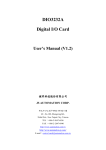
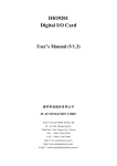
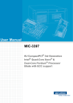
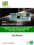
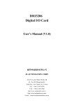
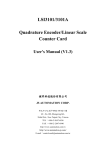
PCIE-Q670 Full-size PICMG 1.3 CPU card Supports LGA1155 Intel® Core™ i7/i5/i3/Pentium® /Celeron® CPU with Intel® Q67, DDR3, VGA/DVI-D, Dual Intel® PCIe GbE, SATA 6Gb/s, PCIe Mini, HD Audio and RoHS USER’S MANUAL (V1.0) 健昇科技股份有限公司 JS AUTOMATION CORP. 新北市汐止區中興路 100 號 6 樓 6F., No.100, Zhongxing Rd., Xizhi Dist., New Taipei City, Taiwan TEL:+886-2-2647-6936 FAX:+886-2-2647-6940 http://www.automation.com.tw http://www.automation-js.com/ E-mail:[email protected] CONTENTS 1. 2. 3. 4. Forward ................................................................................................................................................. 2 Features ................................................................................................................................................. 3 Specifications ........................................................................................................................................ 4 Dimensions(mm) .................................................................................................................................. 6 4.1 PCIE-Q670 Series Dimensions (mm) .......................................................................................... 6 4.2 External Interface Panel Dimensions (mm) ................................................................................. 6 5. Jumper and Connector .......................................................................................................................... 7 5.1 Jumper and Connector Locations ................................................................................................ 7 5.2 Peripheral Interface Connectors................................................................................................... 8 5.3 External Interface Panel Connectors............................................................................................ 8 6. Connector and Jumper setting............................................................................................................... 9 6.1 Internal Peripheral Connectors .................................................................................................... 9 6.1.1 12V Power Connector (CPU12V1) ............................................................................ 9 6.1.2 Audio Kit Connector (J_AUDIO1) ............................................................................ 9 6.1.3 Battery Connector (BAT1) .......................................................................................... 9 6.1.4 DDR3 DIMM Slots (CHA_DIMM1, CHB_DIMM1) ................................................ 9 6.1.5 Digital I/O Connector (DIO1)................................................................................... 10 6.1.6 DVI-D Connector (DVI Model Only) (DVI1) ......................................................... 10 6.1.7 Fan Connector (CPU) (CPU_FAN1) ........................................................................ 10 6.1.8 Floppy Disk Drive Connector (FDD1) ......................................................................11 6.1.9 Front Panel Connector (F_PANEL1) .........................................................................11 6.1.10 I2C Connector (I2C_1) ............................................................................................. 12 6.1.11 Infrared Interface Connector (IR1 CN) .................................................................... 12 6.1.12 Keyboard/Mouse Connector (KB_MS1) .................................................................. 12 6.1.13 Parallel Port Connector (LPT1) ................................................................................ 13 6.1.14 PCIe Mini Card Slot(CN3) ....................................................................................... 14 6.1.15 SATA 3Gb/s Drive Connectors (SATA3, SATA4, SATA5, SATA6) ......................... 15 6.1.16 SATA 6Gb/s Drive Connector(SATA1, SATA2)....................................................... 15 6.1.17 Serial Port Connectors, RS-232(COM1, COM2) ..................................................... 15 6.1.18 Serial Port Connector, RS-422/485 (COM4) ............................................................ 16 6.1.19 SMBus Connector (SMBUS_1)................................................................................ 16 6.1.20 SPI ROM Connector (JSPI1) .................................................................................... 16 6.1.21 TPM Connector (TPM1) ........................................................................................... 16 6.1.22 USB Connectors (USB1, USB2, USB3) .................................................................. 17 6.2 External Peripheral Interface Connector Panel .......................................................................... 17 6.2.1 Ethernet Connectors (LAN1 and LAN2) .................................................................. 17 6.2.2 USB Connectors (USB_C1 and USB_C2) ............................................................... 18 6.2.3 VGA Connector (VGA1) .......................................................................................... 18 7. Ordering Information .......................................................................................................................... 19 1 1. Forward Thank you for your selection of PCIE-Q670 cpu card. Any comment is welcome, please visit our website: www.automation.com.tw for the up to date information. 2 2. Features PICMG 1.3 full-size graphics grade solution LGA1155 CPU socket Intel® Q67 chipset Dual-channel DDR3 DIMMs support up to 16.0 GB Dual independent display by VGA and DVI-D (DVI model only) One PCIe Mini expansion slot Two Intel® PCIe Gigabit Ethernet connectors (LAN2 with Intel® AMT 7.0 support) Two SATA 6Gb/s connectors with RAID function Four SATA 3Gb/s connectors with RAID function TPM V1.2 hardware security function supported by the TPM module High Definition Audio RoHS compliant 3 3. Specifications Form Factor : PICMG 1.3 CPU Supported : LGA1155 Intel® Core™ i7/i5/i3/Pentium® /Celeron® CPU PCH : Intel® Q67 Memory : Two 240-pin 1333/1066 MHz dual-channel unbuffered DDR3 SDRAM DIMMs support (system max. 16.0 GB) Graphics Engine : Supports DirectX 10.1 and OpenGL 3.0 Full MPEG2, VC1, AVC Decode Audio : Supports IEI AC-KIT-888HD audio kit BIOS : UEFI BIOS Ethernet Controllers : Intel® 82583V PCIe Ethernet controller Intel® 82579 PHY with Intel® AMT 7.0 support (LAN2) Super I/O Controller : Fintek F81866 Watchdog Timer : Software programmable supports 1~255 sec. system reset Expansion : One PCIe Mini slot (with USB 2.0/1.1 signal) PCIe signal and PCI signal via golden fingers Supports PCIe x1* or x4** slots on backplane * The BIOS version “B202ARxx.bin” is used for “PCIe x1 signal to four PCIe x1 slots”, such as the IEI PE-5S2-R40 backplane. ** The BIOS version “V0V2ARxx.bin” is used for “PCIe x4 signal to one PCIe x4 slot”, such as the IEI PE-5S-R40 backplane. I/O Interface Connectors : Audio Connector : One internal audio connector (10-pin header) Digital I/O : 8-bit, 4-bit input/4-bit output Display Output : One VGA integrated in the Intel® Q67(rear I/O) One DVI-D integrated in the Intel® Q67 (via 26-pin header to the DVI-D/USB kit; DVI model only) Ethernet : Two RJ-45 GbE ports Fan : One 4-pin wafer connector FDD : One 34-pin floppy disk drive connector Front Panel : One 14-pin header (power LED, HDD LED, speaker, power button, reset button) I2C : One 4-pin wafer connector Infrared : One via 5-pin header Keyboard/Mouse : One 6-pin wafer connector Parallel Port : One parallel port via internal 26-pin box header Serial ATA : Four SATA 3Gb/s connectors (support RAID 0, 1, 5, 10) Two SATA 6Gb/s connectors (support RAID 0, 1, 5, 10) 4 Serial Ports : Two RS-232 via internal box headers One RS-422/485 via internal 4-pin wafer connector SMBus : One 4-pin wafer connector TPM : One via 20-pin header USB Ports : Two external USB 2.0 ports on rear IO Six internal USB 2.0 ports by three pin headers Environmental and Power Specifications : Power Supply : 5V/12V, AT/ATX power supported Power Consumption : [email protected], [email protected] , [email protected], [email protected], [email protected](3.40 GHz Intel® Core™ i7 2600 CPU with two 1333 MHz 2GB DDR3 memory) Operating Temperature : -10ºC ~ 60ºC Humidity :5% ~ 95% (non-condensing) Physical Specifications : Dimensions : 338 mm x 126 mm Weight (GW/NW) : 1200 g / 420 g 5 4. Dimensions(mm) 4.1 PCIE-Q670 Series Dimensions (mm) 4.2 External Interface Panel Dimensions (mm) 6 5. Jumper and Connector 5.1 Jumper and Connector Locations 7 5.2 Peripheral Interface Connectors Connector Type Label +12V ATX power supply connector 4-pin Molex power connector CPU12V1 Audio kit connector 10-pin header J_AUDIO1 Battery connector 2-pin wafer BAT1 DDR3 DIMM sockets 240-pin socket CHA_DIMM1 CHB_DIMM1 Digital I/O connector 10-pin header DIO1 DVI-D connector (DVI model only) 26-pin header DVI1 Fan connector (CPU) 4-pin wafer CPU_FAN1 Floppy disk drive connector 34-pin box header FDD1 Front panel connector 14-pin header F_PANEL1 I2C connector 4-pin wafer I2C_1 Infrared connector 5-pin header IR1 Keyboard and mouse connector 6-pin wafer KB_MS1 Parallel port connector 26-pin box header LPT1 PCIe Mini slot PCIe Mini CN3 SATA 3Gb/s drive connector 7-pin SATA connector SATA3, SATA4, SATA5, SATA6 SATA 6Gb/s drive connector 7-pin SATA connector SATA1, SATA2 Serial port, RS-422/485 4-pin wafer COM4 Serial port, RS-232 10-pin box header COM1, COM2 SMBus connector 4-pin wafer SMBUS_1 SPI ROM connector 8-pin header JSPI1 TPM connector 20-pin header TPM1 USB connectors 8-pin header USB1, USB2, USB3 5.3 External Interface Panel Connectors Connector Type Label Ethernet connector RJ-45 LAN1 Ethernet connector RJ-45 LAN2 USB port USB USB_C1 USB port USB USB_C2 VGA connector 15-pin female VGA1 8 6. Connector and Jumper setting 6.1 Internal Peripheral Connectors 6.1.1 12V Power Connector (CPU12V1) The connector supports the 12V power supply. Pin Description Pin Description 1 GND 2 GND 3 +12V 4 +12V 6.1.2 Audio Kit Connector (J_AUDIO1) This connector connects to an external audio kit. Pin Description Pin Description 1 ACZ_SYNC 2 ACZ_BITCLK 3 ACZ_SDOUT 4 ACZ_PCBEEP 5 ACZ_SDIN 6 ACZ_RST# 7 ACZ_VCC 8 ACZ_GND 9 ACZ_12V 10 ACZ_GND 6.1.3 Battery Connector (BAT1) This is connected to the system battery. The battery provides power to the system clock to retain the time when power is turned off. Pin Description 1 GND 2 Battery+ 6.1.4 DDR3 DIMM Slots (CHA_DIMM1, CHB_DIMM1) The DIMM slots are for DDR3 DIMM memory modules. 9 6.1.5 Digital I/O Connector (DIO1) The digital I/O connector provides programmable input and output for external devices. The digital I/O provides 4-bit output and 4-bit input. Pin Description Pin Description 1 GND 2 VCC 3 Output 3 4 Output 2 5 Output 1 6 Output 0 7 Input 3 8 Input 2 9 Input 1 10 Input 0 6.1.6 DVI-D Connector (DVI Model Only) (DVI1) The DVI-D connector connects to a monitor that supports DVI video input via the DVI-D/USB kit. Pin Description Pin Description 1 Data 2 2 Data 2+ 3 GND 4 NC 5 NC 6 DDC Clock 7 DDC Data 8 NC 9 Data 1 10 Data 1+ 11 GND 12 NC 13 NC 14 VCC 15 GND 16 Hot Plug Detect 17 Data 0 18 Data 0+ 19 GND 20 NC 21 NC 22 GND 23 Clock + 24 Clock 25 GND 26 NC 6.1.7 Fan Connector (CPU) (CPU_FAN1) The fan connector attaches to a CPU cooling fan. Pin Description 1 GND 2 +12 V 3 Rotation Signal 4 PWM Control Signal 10 6.1.8 Floppy Disk Drive Connector (FDD1) The floppy disk drive connector is connected to a floppy disk drive. Pin Description Pin Description 1 GND 2 REDUCE WRITE 3 GND 4 NC 5 NC 6 NC 7 GND 8 INDEX# 9 GND 10 MOTOR ENABLE A# 11 GND 12 DRIVE SELECT B# 13 GND 14 DRIVE SELECT A# 15 GND 16 MOTOR ENABLE B# 17 GND 18 DIRECTION# 19 GND 20 STEP# 21 GND 22 WRITE DATA# 23 GND 24 WRITE GATE# 25 GND 26 TRACK 0# 27 GND 28 WRITE PROTECT# 29 GND 30 READ DATA# 31 GND 32 SIDE 1 SELECT# 33 GND 34 DISK CHANGE# 6.1.9 Front Panel Connector (F_PANEL1) The front panel connector connects to the indicator LEDs and buttons on the computer's front panel. Function Pin Power LED 1 +5V 3 Power Button HDD LED Description Function Pin Speaker 2 +5V N/C 4 N/C 5 GROUND 6 N/C 7 PWR_BTN+ 8 Speaker 9 PWR_BTN- 10 N/C 11 +5V 12 RESET 13 HDD_LED- 14 GROUND Reset 11 Description 6.1.10 I2C Connector (I2C_1) The I2C connector is for system debug. Pin Description 1 GND 2 PCH_GP38_PU 3 PCH_GP39_PU 4 +5VS 6.1.11 Infrared Interface Connector (IR1 CN) The infrared connector attaches to an infrared receiver for use with remote controls. Pin Description 1 VCC 2 NC 3 IR-RX 4 GND 5 IR-TX 6.1.12 Keyboard/Mouse Connector (KB_MS1) The keyboard/mouse connector connects to a PS/2 Y-cable that can be connected to a PS/2 keyboard and mouse. Pin Description 1 +5 VCC 2 Mouse Data 3 Mouse Clock 4 Keyboard Data 5 Keyboard Clock 6 GROUND 12 6.1.13 Parallel Port Connector (LPT1) The parallel port connector connects to a parallel port connector interface or some other parallel port device such as a printer. Pin Description Pin Description 1 STROBE# 2 DATA0 3 DATA1 4 DATA2 5 DATA3 6 DATA4 7 DATA5 8 DATA6 9 DATA7 10 ACKNOWLEDGE# 11 BUSY 12 PAPER EMPTY 13 PRINTER SELECT 14 AUTO FORM FEED # 15 ERROR# 16 INITIALIZE# 17 PRINTER SELECT LN# 18 GND 19 GND 20 GND 21 GND 22 GND 23 GND 24 GND 25 GND 13 6.1.14 PCIe Mini Card Slot(CN3) The PCIe Mini card slot is for installing a PCIe Mini expansion card. Pin Description Pin Description 1 PCIE_WAKE# 2 VCC3 3 NC 4 GND 5 NC 6 1.5V 7 CLKREQ# 8 LFRAME# 9 GND 10 LAD3 11 CLK 12 LAD2 13 CLK+ 14 LAD1 15 GND 16 LAD0 17 PCIRST# 18 GND 19 LPC 20 VCC3 21 GND 22 PCIRST# 23 PERN2 24 3VDual 25 PERP2 26 GND 27 GND 28 1.5V 29 GND 30 SMBCLK 31 PETN2 32 SMBDATA 33 PETP2 34 GND 35 GND 36 USBD 37 NC 38 USBD+ 39 NC 40 GND 41 NC 42 NC 43 NC 44 RF_LINK# 45 NC 46 BLUELED# 47 NC 48 1.5V 49 NC 50 GND 51 NC 52 VCC3 14 6.1.15 SATA 3Gb/s Drive Connectors (SATA3, SATA4, SATA5, SATA6) The SATA drive connectors can be connected to SATA drives and support up to 3Gb/s data transfer rate. Pin Description Pin Description 1 GND 2 TX+ 3 TX 4 GND 5 RX 6 RX+ 7 GND 6.1.16 SATA 6Gb/s Drive Connector(SATA1, SATA2) The SATA drive connectors can be connected to SATA drives and support up to 6Gb/s data transfer rate. Pin 6.1.17 Description Pin Description 1 GND 2 TX+ 3 TX 4 GND 5 RX 6 RX+ 7 GND Serial Port Connectors, RS-232(COM1, COM2) Each of these connectors provides RS-232 connections. Pin Description Pin Description 1 Data Carrier Direct (DCD) 2 Receive Data (RXD) 3 Transmit Data (TXD) 4 Data Terminal Ready (DTR) 5 Ground (GND) 6 Data Set Ready (DSR) 7 Request To Send (RTS) 8 Clear To Send (CTS) 9 Ring Indicator (RI) 10 N/C 15 6.1.18 Serial Port Connector, RS-422/485 (COM4) This connector provides RS-422 or RS-485 communications. Pin Description Pin Description 1 RXD485# 3 RXD485 2 RXD485+ 4 RXD485# 6.1.19 SMBus Connector (SMBUS_1) The SMBus (System Management Bus) connector provides low-speed system management communications. Pin Description 1 GND 2 SMB_DATA 3 SMB_CLK 4 +V5S 6.1.20 SPI ROM Connector (JSPI1) The SPI connector is used to flash the BIOS. Pin Description Pin Description 1 +3.3V 2 GND 3 SPI_CS0 4 SPI_CLK 5 SPI_SO0 6 SPI_SI 7 NC 8 NC 6.1.21 TPM Connector (TPM1) The TPM connector connects to a TPM module. Pin Description Pin Description 1 CLK 2 GND 3 ERAME# 4 NC 5 RESRT# 6 +5V 7 AD3 8 AD2 9 +3V 10 AD1 11 AD0 12 GND 13 SMB_CLK 14 SMB_DATA 15 SB3V 16 SERIRQ 17 GND 18 CLKRUN# 19 PM_SUS_STAT# 20 DRQ# 16 6.1.22 USB Connectors (USB1, USB2, USB3) The USB connectors connect to USB devices. Each pin header provides two USB ports. Pin Description Pin Description 1 VCC 2 GND 3 DATA- 4 DATA+ 5 DATA+ 6 DATA- 7 GND 8 VCC 6.2 External Peripheral Interface Connector Panel The figure below shows the external peripheral interface connector (EPIC) panel. The EPIC panel consists of the following: 6.2.1 Ethernet Connectors (LAN1 and LAN2) The PCIE-Q670 Series is equipped with two built-in RJ-45 Ethernet controllers. Each controller can connect to the LAN through one RJ-45 LAN connector. Pin Description Pin Description 1 MDIA3 2 MDIA3+ 3 MDIA2 4 MDIA1 5 MDIA1+ 6 MDIA2+ 7 MDIA0 8 MDIA0+ LED A Description LED on: linked blinking: data is being sent/received 17 B Description off: 10 Mb/s green: 100 Mb/s orange: 1000 Mb/s 6.2.2 USB Connectors (USB_C1 and USB_C2) The PCIE-Q670 Series has two external USB 2.0 ports. The ports connect to both USB 2.0 and USB 1.1 devices. Pin Description 1 VCC 2 DATA- 3 DATA+ 4 GROUND 6.2.3 VGA Connector (VGA1) The VGA connector connects to a monitor that accepts a standard VGA input. Pin Description Pin Description 1 RED 2 GREEN 3 BLUE 4 NC 5 GND 6 GND 7 GND 8 GND 9 VGAVCC 10 GND 11 NC 12 DDCDAT 13 HSYNC 14 VSYNC 15 DDCCLK 18 7. Ordering Information PRODUCT DESCRIPTIONS JD50PCIEQ670 Full-Size PICMG 1.3 CPU Card Supports 32nm LGA1155 Intel® Core™ i7/i5/i3/Pentium® /Celeron® CPU, Intel® Q67 Chipset, DDR3, VGA/DVI-D, Dual Intel® PCIe GbE, Two SATA 6Gb/s Ports, PCIe Mini, HD Audio and RoHS 19