1
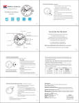
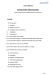
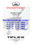
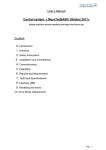
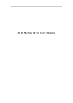
OFP401P0189 Color Sensor Operating Instructions Last update: 23 May 2013 EN 2 Table of contents 1. Proper Use 4 2. Safety Precautions 4 3. EC Declaration of Conformity 4 4. Technical Data 4.1. Connection Diagram 4.2. Housing dimensions 4.3. Control Panel 4.4. Complementary Products (see catalog) 5 6 6 7 7 5. Mounting instructions 8 6. Initial Operation 6.1. Initial Operation 6.2. Default Settings 8 8 9 7. Functional description 7.1.RUN 7.2. Pin function 7.3. E/A setting 7.3.1. Switching Output Assignment Teach-In 7.3.2. Switching Output Window Teach-In 7.3.3. Switching Output Sample Teach-In 7.3.4. Switching Output Tolerance 7.3.5. Tolerance H/S/L 7.3.6. Switching Output NPN/PNP 7.3.7. Switching Output NO/NC 7.3.8. Switching Output On-Delay 7.3.9. Switching Output Off-Delay 7.3.10. Switching Output Pulse Length 7.4.Display 7.4.1. Display Mode 7.4.2. Display Intensity 7.5.Assistant 10 12 12 13 14 15 15 15 16 16 16 17 17 18 18 18 19 19 EN 7.6. Expert Menu 7.7. Operating mode 7.8. Filter 7.9. Emitted Light 7.10.E/A Test 7.10.1. Test Ax 7.11.Interface 7.12.Sensor type 7.14.Information 7.15.Reset 7.16.Password 8. More Settings via the RS-232 Interface 3 20 20 20 21 21 21 22 22 23 23 23 24 EN 4 1. Proper Use wenglor Color Sensors detect colors which have been previously defined. Surface color can be detected in scanning mode operation. 2. Safety Precautions ••This operating instruction is part of the product and must be kept during its entire service life. ••Read this operating instruction carefully before using the product. ••Installation, start-up and maintenance of this product has only to be carried out by trained personnel. ••Tampering with or modifying the product is not permissible. ••Protect the product against contamination during start-up. ••Not a safety component in accordance with the EU Machinery Directive. 3. EC Declaration of Conformity The products are developed, constructed and manufactured according to the directive 2004/108/EC. The following international standards and specifications apply: EN 60947-5-2:2007Low-voltage switchgear and control gear, Part 5-2: Control circuit devices and switching elements – Proximity switches Any additional standards which are applicable for the given application must be observed. RoHS EN 5 4. Technical Data Order No. Working Range Working Distance Light Source Service Life (Tu = 25 °C) Max. Ambient Light Light Spot Diameter Supply Voltage Current Consumption (Ub = 24 V) Switching Frequency Response Time Temperature Range Switching Outputs Switching Output Voltage Drop PNP Switching Output/Switching Current Short Circuit Protection Reverse Polarity Protection Overload Protection Interface Digital Inputs Protection Class Adjustment Housing Degree of Protection Connection NO/NC switchable Configurable as PNP/NPN/Push-Pull RS-232 Interface Error Output Contamination Output OFP401P0189 30...40 mm 35 mm White Light 100000 h 10000 Lux 3 mm 10...30 V < 80 mA 1.8 kHz 300 µs –25...60 °C 3 1.5 V 100 mA yes yes yes RS-232 2 III Teach-In Plastic IP68 M12 × 1; 8-pin EN 6 4.1. Connection Diagram OY1P303P0189 Legend Supply Voltage + Supply Voltage 0 V Supply Voltage (AC Voltage) Switching Output Switching Output Contamination/Error Output Contamination/Error Output Input (analog or digital) Teach Input Time Delay (activation) Shielding Interface Receive Path Interface Send Path Ready Ground Clock Output/Input programmable (NO) (NC) (NO) (NC) Power over Ethernet Safety Input Safety Output Signal Output not connected 4.2. Housing dimensions Test Input Test Input inverted Trigger Input Analog Output Ground for the Analog Output Block Discharge Valve Output Valve Control Output + Valve Control Output 0 V Synchronization Receiver-Line Emitter-Line Grounding Switching Distance Reduction Ethernet Receive Path Ethernet Send Path Interfaces-Bus A(+)/B(–) Emitted Light disengageable Magnet activation Input confirmation Contactor Monitoring Wire Colors according to DIN IEC 757 Black Brown Red Orange Yellow Green Blue Violet Grey White Pink Green Yellow EN 7 4.3. Control Panel X2 60 23 20 22 20 = Enter Button 22 = Up Button 23 = Down Button 60 = Display 4.4. Complementary Products (see catalog) wenglor offers Connection Technology providing field wiring means. Suiting Mounting Technology No. 380 Suiting Connection Technology No. 89 S74 Interface Cable S232W3 Protection Housing Sets ZSP-NN-02 Protection Housing Sets ZSV-0x-01 EN 8 5. Mounting instructions During the operation of the Sensors, the corresponding electrical and mechanical regulations, as well as safety regulations must be observed. The Sensor must be protected from mechanical impact. 10…30° 35 mm Mounting for glossy objects: 6. Initial Operation 6.1.Initial Operation Connect the sensor to the supply voltage. After initialization the sensor shows the indication screen and is ready for operation. During the first commissioning and after a reset you can first of all select the menu language by simply pressing a button (see Fig. 1). Fig. 1: Set menu language The functions of the keys appear in the display as follows: 5 : Navigate up. 6 : Navigate down. : Selection is acknowledged with the enter key. Meaning of the menu points: Next: One level down in the menu. 3Back: One level up in the menu. 7 Run/Terminate: Change to the display mode: Change to the configuration menu by pressing any button. EN 9 Notice: If no setting is made in the configuration setting for a duration of 30 s, the sensor automatically jumps back into the display view. By pressing the button once again, the sensor jumps back to the menu view used last. Settings made are adapted when quitting the configuration menu. Important: Do not use pointed objects for sensor setting. Otherwise you risk damaging the buttons. Assistant: The sensor is equipped with an assistant for simplified adjustment to the respective application. After cancelling the configuration assistant, the complete menu appears at the display. 6.2. Default Settings Pin function Outputs Display Expert menu Operating Mode Filter Emitted light Interface Type Select Language Password A1 A2 E/A3 E4 Teach mode Tolerance Tolerance H Tolerance S Tolerance L PNP/NPN/Push-pull NO/NC On-Delay Off-Delay Impulse Mode Intensity Baud rate Activate Change OFP401P0189 Switching Output Switching Output Switching Output Interface T Window Small Small Small Small Push-pull NO 0 ms 0 ms 0 ms Outputs Screen saver Off Detection 64 Medium 38400 OFP English Off 0 EN 10 7. Functional description Run Pin Function E/A Configure A1 A2 E/A3 E4 Depends on Pin Function: A1 Switch A2 Switch E3 Ext T A3 Deactivated Switch Error Contaminate Emitted Light Ext T A1 Ext T A2 Trigger Interface During Switching Output T Assignment* T Window Teach OK/NOK Tolerance* Tolerance Maximum Very large Large Middle Tolerance H Tolerance S Tolerance L NPN/PNP NO/NC Assistent Teach Output Expert Menu On Off NO NC Value in ms Off-Delay Value in ms Impulse Value in ms T External Ub active Ub inactive During Input Ub active Ub inactive Mode Rotate Intensity PNP NPN Push-Pull On-Delay During Error Output or Contamination Output NPN/PNP NO/NC Display <T> for Teach-In T Sample Outputs Bar Graph Min Medium Max Power Save Screensaver * Visibility depends on the selected settings (details are provided in the corresponding chapter) Menu items that are presented in bold are always displayed in the menu. The other menu items appear only when the Expert Menu is activated. PNP NPN Push-Pull NO NC Small Very small Minimum Customized EN 11 Operating Mode Detection Assignment Filter 1 2 4 8 16 Emitted Light Bright Medium Dark Off E/A Test 32 1024 64 2048 128 4096 256 512 Test A1 Test A2 Test A3 Test E3 Test E4 Interface 4800 O 9600 O 19200 O 38400 O 57600 O 115200 Type Select OFP FP Language Deutsch English Français Español Italiano Info Display order number, software version and type of Sensor Reset <R> for Reset Password Enable Change Lock On, Off On, Off On, Off Run Mode Input On, Off Password: 0 – 9999 Run-Run Mode EN 12 Below is an explanation of the functions of each menu item. 7.1. RUN Sensor switches to display mode. Set pin function E/A with corresponding condition. If E/A is not displayed, it is deactivated in the pin function menu item. Display of the current signal strength Meaning Condition 1 Condition 2 Condition 3 Condition 4 Switching Output Switched Not switched – – Error Output OK No signal – – Contamination Output OK Signal too low – – Switch off emitted light Emitted Light on Emitted Light off – – T Active T Inactive – – Trigger Input Active Inactive – – Signal Strength OK Signal too low Teach-In Input Signal too high No signal 7.2. Pin function The Pin function is used to determine the function of pins A1, A2, E/A3 and/or E4 since the pins may be used for different functions. A1 Deactivated Switch Error Contamination 3 Back 7 Run A2 Deactivated Switch Error Contamination 3 Back 7 Run Configuration of Pin A1 Deactivated: Deactivation of the output Switch:Switching Output Error: Error Output Contamination: Contamination Output Configuration of pin A2 Deactivated: Deactivation of the output Switch:Switching Output Error: Error Output Contamination: Contamination Output EN E/A3 Deactivated Switch Error Contamination Emitted Light Ext T A1 Ext T A2 Trigger 3 Back 7 Run E4 Interface Trigger 3 Back 7 Run 13 Configuration of pin E/A2 Deactivated: Deactivation of the output Switch:Switching Output Error: Error Output Contamination: Contamination Output Emitted Light: Input for switching on/off the emitted light Ext T A1: Teach input for A1 Ext T A2: Teach input for A2 Trigger:Input for sensor triggering Configuration of pin E4 Interface: Input for serial interface Trigger:Input for sensor triggering 7.3. E/A setting Depending on the preset pin function, the name is displayed in this menu item, e.g. A1 Switch or e.g. E1 Laser. Each menu item includes the following sub items: For Switching Output If the pin is preset as Switching Output, the following functions may be set: A1 Switch/A2 Switch T Assignment T Window T Sample Tolerance Tolerance H Tolerance S Tolerance L NPN/PNP NO/NC On-Delay Off-Delay Impulse 3 Back 7 Run Sensor settings for switching outputs T Assignment:Teach-In of a color which is assigned to the output (only visible if “Assignment” operating mode is set) T Window: Teach-In of a tolerance window in which the sensor is switched. T Sample: Additional Teach-In of an OK or NOK sample Tolerance: Specification of the color tolerance level ** Tolerance H: Specification of the color tolerance level “color value”* Tolerance S: Specification of the color tolerance level “saturation value”* Tolerance L: Specification of the color tolerance level “brightness value”* NPN/PNP: Configuration of the output NO/NC: Configuration of the output On-Delay: On-Delay * Off-Delay: Off-Delay * Impulses: Impulse duration * * Only visible if the expert menu “on” is set. ** Only visible if the expert menu “off” is set. These menu items are described in more detail in chapter 7.3.1 to 7.3.10. EN 14 For error and contamination output If the pin is set as error or contamination output, the following functions can be set: A1 Error (example) NPN/PNP NO/NC 3 Back 7 Run A1 and/or A2 as error output or contamination output NPN/PNP: Configuration of the output NO/NC: Configuration of the output Explanations for “NPN/PNP” are provided in chapter 7.3.6 on page 16. Explanations for “NO/NC” are provided in chapter 7.3.7 on page 16 For emitted light switch-off input, external teach, trigger If the pin is set as input for e.g. emitted light switch-off, it is possible to make a setting for input Ub active or Ub inactive: E3 Emitted Light (example) Ub active Ub inactive 3 Back 7 Run Setting E3 and/or E4 input Ub active: The input is activated if supply voltage (Ub) is applied. Ub inactive: The input is activated if no voltage is applied. 7.3.1. Switching Output Assignment Teach-In Notice: The menu item is only visible if the expert menu is “on” and the operating mode is set to “Assignment”. T Assignment <T> for Teach-In Assignment Teach-In Teach-In Assignment-Teach-In process: 1) Adjust light spot to the object color 2) Press “T” button. -> The object color is taught in and allocated to the appropriate output. EN 15 7.3.2. Switching Output Window Teach-In There are two switching points for window Teach-In. The size of the window is referred to as tolerance. If a color is within the window, the sensor switches. T Window <T> for Teach-In Window Teach-In Teach-In Window-Teaching process: 1) Align illuminated spot with the background (if available) or to the object. 2) Press “T” button. –> The switching points are taught in. Notice: •T Sample: Additional Teach-In of OK or NOK samples in order to adjust tolerance. • In the “Tolerance” menu item (see chapter 7.3.4), the size of the window width can be reduced or increased. 7.3.3. Switching Output Sample Teach-In T Sample OK Teach OK/NOK ↵ NOK Sample Teach-In Teach-In Sample Teaching process: 1) Teach-In of OK sample • Align light spot with the object. • Press “OK” button. -> Tolerance is increased. 2) Teach-In of NOK sample • Align light spot with the object. • Press “NOK” button. -> Tolerance is decreased. 7.3.4. Switching Output Tolerance Notice: The menu item is only visible if the expert menu is set to “off”. Tolerance Maximum Very large Large Middle Small Very small Minimum Changing tolerance Maximum: Tolerance is set to a maximum value. Very large: Tolerance is set to a very large value. Large: Tolerance is set to a large value. Middle: Tolerance is set to a medium value. Small: Tolerance is set to a small value. Very small: Tolerance is set to a very small value. Minimum: Tolerance is set to a minimum value. EN 16 7.3.5. Tolerance H/S/L The menu item is only visible if the expert menu is “on” and the operating mode is set to “Detection”. Tolerance Maximum Very large Large Middle Small Very small Minimum Customized Changing tolerance Maximal: Tolerance is set to a maximum value. Very large: Tolerance is set to a very large value. Large: Tolerance is set to a large value. Middle: Tolerance is set to a medium value. Small: Tolerance is set to a small value. Very small: Tolerance is set to a very small value. Minimum: Tolerance is set to a minimum value. Customized: By pressing the “+” , tolerance can be increased. By pressing the “–” , tolerance can be decreased. Keep the button pressed to achieve larger jumps in value. 7.3.6. Switching Output NPN/PNP NPN/PNP PNP NPN Push-pull 3 Back 7 Run Output configuration A load or the evaluation device is connected between the negative PNP: pole (supply) and the output. If switched, the output is connected with the positive pole via an electric switch. NPN: A load or the evaluation device is connected between the positive pole (supply) and the output. If the sensor switches, the output is connected with the negative pole via an electric switch. Push-pull: Push-pull output. Acts like an electronic switch which optionally switches the output to the positive pole or the negative pole. 7.3.7. Switching Output NO/NC NO/NC NO NC 3 Back 7 Run Output configuration Normally open. NO: The output closes as soon as an object reaches the switching point. NC: Normally closed. The output opens as soon as an object reaches the switching point. EN 17 7.3.8. Switching Output On-Delay The On-Delay is an adjustable extension of the response time. Object Output On-Delay Notice: The menu item is only visible if the expert menu is set to “on” On-Delay On-Delay in ms Setting of On-Delay By pressing the “+” or “–” button, a On-Delay from 0 ms to 10000 ms can be set. Keep the button pressed to achieve larger jumps in value. 7.3.9. Switching Output Off-Delay The Off-Delay is an adjustable extension of the drop-out time. Object Output Off-Delay Notice: The menu item is only visible if the expert menu is set to “on” Off-Delay Off-Delay in ms Setting of Off-Delay By pressing the “+” or “–” button, a Off-Delay from 0 ms to 10000 ms can be set.. Keep the button pressed to achieve larger jumps in value. Notice: If an impulse length has been set, no Off-Delay can be set. In this case, the notice “Impulse” will appear in the control panel! EN 18 7.3.10. Switching Output Pulse Length The pulse length defines how long the switching state is held. The function can be combined with a response time delay. Object Impulse Pulse combined with ON Delay Pulse Length ON Delay Pulse Length Note: The menu item is only visible if Expert Menu “On” has been set. Impulse Pulse length in ms Set pulse length A pulse length of 0 to 10000 ms can be set by pressing the “+” key or the “–” key. You can keep a key pressed for a longer time in order to make larger numerical jumps. 7.4. Display Display Mode Rotate Intensity 3 Back 7 Run Adjusting the display device Mode: Select display mode (see chapter 7.4.1) Rotate: Rotate display by 180°. The display is rotated by 180° by pressing the key. The rotation is canceled by pressing this key again. Intensity: Set the display intensity (see chapter 7.4.2) 7.4.1. Display Mode Mode Outputs Bar Graph 3 Back 7 Run Select display mode Outputs:The condition of each output is indicated on the display. Bar Graph:The RGB color spaces / shares of the object are indicated in a bar graph. EN 19 7.4.2. Display Intensity Intensity Min Normal Max Power save Screen saver 3 Back 7 Run Set the display intensity Min: The intensity of the display is set to a minimum value. Medium: The intensity of the display is set to a normal value. Max: The intensity of the display is set to a maximum value. Power save: The display switches off after one minute without a button being pressed and automatically switches back on when a button is pressed. Screen saver:The colors of the display are inverted every minute. 7.5. Assistant Assistant Output Teach-In 4 Next 3 Back 7 Run Starting/using the assistant The sensor is equipped with an assistant for the simplified setting to each application. If you abort the configuration assistant, you will return to the comprehensive menu. If you use the assistant, you will get the following support for teaching in object colors: Select output O A1 O A2 O A3 4Next 3Back 7 Exit Aligning light spot with the color O Teach-In (T) 4Next 3Back 7 Exit Does the sensor switch reliably? <Ax Display> O Yes O T Sample OK O T Sample NOK O No 4Next 3Back 7 Exit Want to teach in another output? O Yes O No 4Next 3Back 7 Exit Here you can select the output for which a color should be taught in. Acknowledge your selection always with 4Next in order to access the next window. Align your object with the working area and select Teach-In (T). You will get a message whether Teach-In was successful. Select <Ax Display> in order to check in the OLED display whether each taught-in output reliably switches to the taught-in color. If the output does not switch reliably, you have the following options: •T Sample OK: You may teach in another OK sample. This increases the tolerance. •T Sample NOK: You may teach in a NOK sample. This decreases the tolerance. •No: You may completely re-Teach-In the color. Select “Yes” to teach in another color on another output. Select “No” to quit the assistant. EN 20 7.6. Expert Menu Depending on whether the expert menu is “on” or “off”, different menu items and sub-items appear in the menu. The expert menu is disabled in the default settings. Thus, the menu is shorter and easier to use. If the available menu items are not sufficient for the application solution, the expert menu can be enabled and the entire scope of sensor functions can be used. Expert Menu On Off 3 Back 7 Run Enable or disable expert menu On:The expert menu is disabled and only a few menu items are displayed. Off: The expert menu is enabled and all menu items are displayed. 7.7. Operating mode Notice: The menu item is only visible if the expert menu is set to “on”. Operating mode Detection Assignment 3 Back 7 Run Select operating mode Detection: In the “Detection” operating mode, color windows are taught in to an output. The sensor detects the taught-in colors within a certain range if they are within the tolerance (see chapter 7.3.4/7.3.5). Assignment: In the “Assignment” operating mode, one color each can be taught in and assigned to the outputs. The sensor evaluates the current color value and assigns it to the most similar color of the corresponding output. Thus, one of the outputs is always enabled in this operating mode. Thus, the reliable assignment of all object colors is possible. 7.8. Filter Note: The menu item is only visible if Expert Menu “On” has been set. Filter 4 8 16 32 64 128 256 512 1024 2048 4096 3 Back 7 Run Number of values for averaging. The filter (filter size) is the number of measured values the sensor uses for averaging. The larger the filter, the slower the response time of the sensor. EN 21 7.9. Emitted Light In the “Emitted Light” menu item, the intensity of the emitted light can be modified or the emitted light can be switched off. Notice: The menu item is only visible if the expert menu is set to “on”. Emitted Light High Medium Low Off 3 Back 7 Run Set emitted light High: The intensity of the emitted light is set to “bright”. Due to the increased signal strength, dark objects with low remission are more easily detected. Medium: The intensity of the emitted light is set to “normal”. Low: The intensity of the emitted light is set to “dark”. Due to the reduced signal strength, the color value of very bright objects is more easily detected. Off: The own emitted light is switched off, and only the extraneous light is evaluated. Thus, even luminous objects can be detected. 7.10. E/A Test This function manually changes the outputs, independently of the actual measurement value of the Sensor. In that way it is possible to check, for example, whether the outputs are properly connected to a controller or whether there is a fault on the cable that modifies the output value. It can likewise be tested whether a voltage is arriving at an input pin. The test is automatically terminated when you leave the test menu. Note: The menu item is only visible if Expert Menu “On” has been set. Only the functions for which the pin is set are displayed in each case. E/A Test Test A1 Test A2 Test A3 Test E3 Test E4 3 Back 7 Run E/A Test of the inputs and outputs Test A1: Test output 1 (see chapter 7.10.1) Test A2: Test output 2 (see chapter 7.10.1) Test A3: Test output 3 (see chapter 7.10.1) Test E3: Display whether 0 V or 24 V is present at input 3 Test E4: Display whether 0 V or 24 V is present at input 4 7.10.1. Test Ax Test Ax On Off 3 Back 7 Run Switch outputs on or off On: Switch output on (24 V) Off: Switch output off (0 V) EN 22 7.11. Interface Note: The menu item is only visible if the expert menu is set to “on”. Baud rate 4800 9600 19200 38400 57600 115200 3 Back 7 Run Setting the baud rate 4800: 4800 baud 9600: 9600 baud 19200: 19200 baud 38400: 38400 baud (standard setting) 57600: 57600 baud 115200: 115200 baud 7.12. Sensor type Notice: The menu item is only visible if the expert menu is set to “on”. Type Select OFP FP 3 Back 7 Run Set type select OFP:All described menu items are enabled and the interface is issued according to the OFP interface protocol. FP: The sensor is compatible to the predecessor product FP04PCT80. 7.13. Language The menu language can be changed in the menu item “Language”. The user is automatically prompted for his desired language at initial operation and after each reset. The menu item is only visible if the expert menu is set to “on”. Language Deutsch English Français Español Italiano 3 Back 7 Run Set menu language The menu appears in the selected language immediately after selection. EN 23 7.14. Information Note: The menu item is only visible if Expert Menu “On” has been set. The following information about the Sensor is displayed in the “Info” menu item. Info Order number Software version Type Select 3 Back 7 Run 7.15. Reset The Sensor setting can be reset to the delivery state in the menu item “Reset”. The settings in the delivery state can be found in chapter "6.2. Default Settings" on page 9. The menu item is only visible if the expert menu is set to “on”. Reset <R> for Reset Set back to the delivery state The Sensor settings that have been made can be reset to the delivery state by pressing the “R” key. 7.16. Password Password protection prevents against unintended changing of the set data. The menu item is only visible if the expert menu is set to “on”. Password Activate Change Lock 3 Back 7 Run Set password functionality Activate: Turn password protection on or off. If password protection is activated, the operation of the Sensor is disabled after supply power has been interrupted and is only enabled after successful password input. Change: Change password. Lock Locking Sensor causes an immediate disabling of operation if activate Password is set to “On”. If the password function has been activated, the password must be entered each time supply power to the Sensor is interrupted. After entering the correct password with the + or – key, the entire menu is enabled and the Sensor is ready for use. ••The password function is deactivated upon shipment from the factory. ••Passwords can be selected within a range of 0000 to 9999. Be sure to make a note of the new password before exiting the “change password” function! If the password is forgotten, it must be overwritten with a master password. The master password can be requested by e-mail from [email protected]. EN 24 8. More Settings via the RS-232 Interface The interface makes use of the software handshake procedure. All settings can be configured at a PC and uploaded to the device. RS-232 interface connections RxD (5) and TxD (4) are linked to minus (pin 3), and can be connected to the corresponding terminals at the communication partner. Interface configuration: Adjustable baud rate, 8 data bits, no parity, 1 stop bit Connect the Sensor via wenglor interface cable S232W3 to the PC or controller as follows ••Disconnect 8-pin interface cable ZAS89xxx from the Sensor ••Plug interface cable S232W3 directly into the Sensor ••Plug 8-pin connection cable ZAS89xxx directly into the interface cable ••Connect 9-pin SUB-D plug of the S232W3 into the serial port of the PC or controller ••Switch on power supply Sensor S232W3 Power Supply Outputs PC or Controller You can download the OFP interface protocol as PDF document from our homepage www.wenglor.com in the Download link. 9. Maintenance Instructions ••This wenglor Sensor is maintenance-free. ••It is advisable to clean the lens and the display, and to check the plug connections at regular intervals. ••Do not clean with solvents or cleansers which could damage the device. 10. Proper Disposal wenglor sensoric gmbh does not accept the return of unusable or irreparable products. Respectively valid national waste disposal regulations apply to product disposal.