1
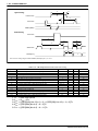
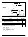
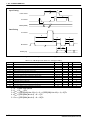
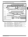
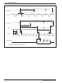
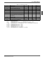
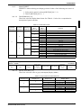
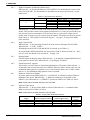
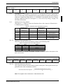
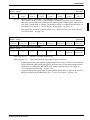
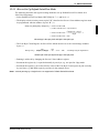
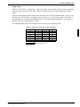
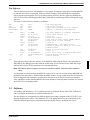
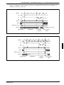
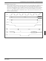
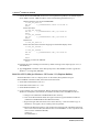
5: ADVANCED TECHNIQUES
Examples
Example 5
Display 200 scanlines of image 1 and 40 scanlines of image 2. Image 2 is located first
(offset 0) in the display buffer followed immediately by image 1. Assume a 320 × 240
display and a color depth of 4 bpp.
1. Calculate the Scre en 1Vertical Size register values.
vertical_size = 200 = C8h
Write the Vertical Size LSB, REG[13h], with C8h and Vertical Size MSB, REG[14h], with a
00h.
2. Calculate the Screen 1 Start Word Address register values.
Screen 2 is located first in display memory, therefore we must calculate the number of bytes
taken up by the screen 2 data.
bytes_per_line = pixels_per_line / pixels_per_byte = 320 / 2 = 160
total bytes = bytes_per_line × lines = 160 × 40 = 6400.
Screen 2 requires 6400 bytes (0 to 6399) therefore the start address offset for screen 1 must be
6400 bytes. (6400 bytes = 3200 words = C80h words)
Set the Screen 1 Start Word Address MSB, REG[0Dh], to 0Ch and the Screen 1 Start Word
Address LSB, REG[0Ch], to 80h.
3. Calculate the Screen 2 Start Word Address register values.
Screen 2 display data is coming from the very beginning of the display buffer. All there is to do here
is ensure that both the LSB and MSB of the Screen 2 Start Word Address registers are set to zero.
2-22
EPSON
S1D13705F00A PROGRAMMING NOTES
AND EXAMPLES (X27A-G-002-01)