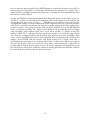
1
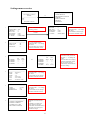
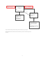
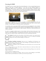
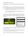
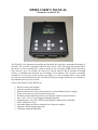
D500X USER’S MANUAL
Firmware version 2.2.6
The D 500X is an ultrasound recording unit intended for long-term, unattended recording of
bat calls. The recorder is equipped with four slots for CF cards. The triggering system allows
the device to start recording as a sound is detected. The recording length can be selected in
steps from 0.3 up to 20 seconds. In order not to fill the card too fast at locations with high
activity, a minimum time between two recordings can be applied. The recorder is normally
operated in a low-power mode with no pre-trigger (i.e. the recording starts as the sound
exceeds the chosen threshold level), but both pre-and post-trigger functions are available in
the standard (not low-power) mode.
Some of the features of the D500X are:
•
•
•
•
•
•
•
•
•
•
•
Built-in electret microphone
Jack for external microphone
Powered either from 4 AA cells (internal) or external batteries/power supply
Timer to turn the unit on/off at desired intervals
Weather-protected housing (built-in microphone requires some protection)
Size: 165 x 170 x 53 mm, rugged aluminium housing
Sampling rates: 44.1 kHz, 300 kHz and 500 kHz (optimized for 500 kHz)
ADC resolution: 16 bits
Selectable high-pass filter to attenuate low frequency signals
Optional external trigger input jack
Time/date stamped sound files
GUARANTEE
This product is guaranteed against defects in material and workmanship for a period of one year from the date of purchase. In
order for the guarantee to be granted, a proof of purchase (normally the original invoice/receipt) is required and the serial
number label must not be removed from the product. Pettersson Elektronik AB, Sweden (“Pettersson”) will repair or replace
the product if it proves to be defective during the guarantee period, provided it is returned to Pettersson. No other guarantee is
expressed or implied.
This product does not contain any user-serviceable parts. Do not open it and always refer servicing to the manufacturer or any
other party approved by the manufacturer.
The guarantee covers none of the following:
1. Damage to the product resulting from abuse and misuse, including but not limited to (a) the failure to use this product for
its normal purpose or in accordance with Pettersson’s instructions on the proper use and maintenance of this product and (b)
the installation or the use of this product in a manner inconsistent with the technical or safety standards in force in the country
where the product is used.
2. Damage to the product resulting from non-authorized modifications made to the product.
3. Repairs done by non-authorized technicians.
4. Accidents or similar causes beyond the control of Pettersson, including but not limited to lightning, water, fire and public
disturbances.
LIMITATION OF LIABILITIES
In no event shall Pettersson be liable for any special, incidental or consequential damages of any nature including, but not
limited to, damages resulting from loss of profit or revenue, recall costs, claims for service interruptions or failure to supply
downtime, testing, installation or removal costs, costs of substitute products, property damage, personal injury, death or legal
expenses. The customer's recovery from Pettersson for any claim shall not exceed the purchase price paid by the customer for
the goods, irrespective of the nature of the claim, whether in warrant, contract or otherwise. The customer shall indemnify,
defend and hold Pettersson harmless from any claims brought by any party regarding products supplied by Pettersson and
incorporated into the customer’s product.
Pettersson assumes no responsibility for any damage or loss resulting from the use of this manual.
Pettersson assumes no responsibility for any loss or claims by third parties which may arise through the use of the D500X.
Pettersson assumes no responsibility for any damage or loss caused by deletion of data as a result of malfunction, repairs or
battery replacement. Be sure to back up all important data on other media to protect against its loss.
PRODUCT SAFETY NOTICE AND RESTRICTIONS
This product is intended for commercial use only. Products sold by Pettersson are not designed, intended or authorized for
use in life support, life sustaining, human implantable, nuclear facilities, flight control systems, or other applications in which
the failure of such products could result in personal injury, loss of life or catastrophic property damage. If the customer uses
or sells the products for use in any such applications: (1) the customer acknowledges that such use or sale is at the customer's
sole risk; (2) the customer agrees that Pettersson is not liable, in whole or in part, for any claim or damage arising from such
use; and (3) the customer agrees to indemnify, defend and hold Pettersson harmless from and against any and all claims,
damages, losses, costs, expenses and liabilities arising out of or in connection with such use or sale.
Windows is a registered trademark of Microsoft Corporation.
CompactFlash is a registered trademark of SanDisk Corporation.
Other company, product and service names mentioned in this manual, may be trademarks of others.
Specifications are subject to change without notice.
© Pettersson Elektronik AB, 2014
May 2014
2
What's new in version 2.2.6?
* Improved battery voltage monitoring.
* The extended logging of various events to the log file can now be disabled/enabled in the
F1/Utilities/Battery Settings menu.
* The battery voltage warning and shut down voltages can now be changed by the user in the
F1/Utilities/Battery Settings menu. This is useful to make the battery monitoring system
compatible with different types of batteries/power supplies.
* Various bug fixes.
Upgrading from version 2.1.3? Here are the changes from version 2.1.3 to 2.2.5
* New "Trig Sensitivity" system. The algorithm now tries to avoid making recordings that are
not "pulse-like" (i.e. avoid recording signals of long duration).
* The recorded files are not "Write protected".
* "File create" and "file modified" time in files changed to better represent the true time.
* If the power is switched off or otherwise fails while the detector is in the Automatic
Recording mode, the detector will automatically resume the recording session when power
returns.
* More information in the D500X log file. The detector now logs when a timer turns on/off,
there is an automatic log entry every whole hour, a log of low battery voltage events, etc.
* Accepts CF cards without a partition.
* 2 sec and 4 sec recording time added.
* New timer function. The old timer function is still available, but in addition to this a
"sunrise/sunset relative timer" function has been added. The latitude, longitude, time zone and
daylight saving time is entered in the Time settings and the times for sunset and sunrise are
automatically calculated.
* CF cards in all four slots can be formatted in the D500X, not just in slot 1.
* Various bug fixes and cosmetic changes.
3
Top panel overview
Pettersson
ULTRASOUND DETECTOR D 500X
The REC indicator in
on while the detector is
recording. It flashes
momentarily once
every 5 seconds in the
sleep mode.
The F1 key is used to
enter the Settings
menu.
The POWER LED is on
when the detector is
switched on. It flashes
momentarily once every 5
seconds in the sleep mode.
REC
F2
The F2 key is reserved
for service/calibration
purposes.
The ON/OFF key is
used to switch the
detector on/off or to
exit the ”sleep” mode.
It is also used to
temporarily turn on the
display when the
detector is in the sleep
mode.
F1
ENTER
REC
The ENTER key is used to
confirm various selections
made.
In the standard mode it is
also used to enter the
“profile selection mode”.
The ARROW keys are used
to navigate in various
menus.
In the standard mode the
left/right arrow keys are
used to change the input
gain setting.
4
The REC key is used to
start recording or to enter
the automatic recording
mode, depending on
which mode was chosen.
ESC
The ESC key is used to
undo various operations.
CF card panel overview
The protection cover must be removed to access the power switch and CF card slots.
CF card slot #1
CF card slot #3
CF card slot #2
CF card slot #4
POWER
EXT OFF INT
Power switch to select
external or internal
batteries. In the mid
position all power is
switched off.
Microphone panel overview
External trigger
jack
Battery holders for
2 x 2 AA cells
External power jack,
5.5 – 8 V DC
5
External
microphone jack
Built-in electret
microphone
Settings menu overview
PROFILE2
---------------------------------CF1: M00337 (6.367G)
READY
---------------------------------dB …
CF …
2013/05/31 18:05:20
1
2
3
4
5
6
PROFILE
= USER0
--------------------------------------SAMP. FREQ = 500
PRETRIG
=1
REC. LEN
=5
HP-FILTER
= YES
AUTOREC
= YES
T. SENSE
= VERY HIGH
RECORDING SETTINGS
--------------------------------------INPUT GAIN
=45
TRIG LEV
=36
INTERVAL
=5
ABSOLUTE TIMERS
--------------------------------------ON
OFF
ATIMER1
18:10 04:40
ATIMER2
--:---:-ATIMER3
--:---:-ATIMER4
--:---:--
TIME SETTINGS
--------------------------------------DATE : 2013-05-31
TIME
: 17:23
ZONE : +01
LAT
: 59 38 41 N
LON
: 017 38 20 E
DST
: EUR 0331 1027
DISPLAY
--------------------------------------MODE
= AUTO
TIMEOUT
= 10
BRIGHTNESS
= 128
UTILITIES
--------------------------------------1-SHOW CF PROPERTIES
2-SHOW CF TIMING
3-FORMAT CF-CARD
4-BATTERY SETTINGS
D500X SETTINGS
--------------------------------------1-USER PROFILES
2-RECORDING SETTINGS
3-TIMERS
4-TIME SETTINGS
5-DISPLAY
6-UTILITIES
F1
SAMP. FREQ
PRETRIG
REC. LEN
HP-FILTER
AUTOREC
T. SENSE
Use ← → to switch between
recording profiles
ENTER
= 500
=1
=5
= YES
= YES
= VERY HIGH
Use ↑↓ to switch between
parameters and ← → to change
the values.
Press ENTER to save changes
and return to READY screen.
Use ↑↓ to switch between
parameters and ← → to change
the values.
Press ENTER to save changes
and return to READY screen.
or
RELATIVE TIMERS
--------------------------------------ON
OFF
RTIMER1
+00:15 -00:15
RTIMER2
--:---:-RTIMER3
--:---:-RTIMER4
--:---:-SET/RISE
21:35 03:55
Use ↑↓ to switch between
parameters and ← → to change
the values.
Press ENTER to save changes
and return to READY screen.
Use ↑↓ to switch between
parameters and ← → to change
the values.
Press ENTER to save changes
and return to READY screen.
CF PROPERTIES and CF
TIMING for advanced users
only.
FORMAT CF-CARD will
erase all data on the card.
BATTERY SETTINGS used to
set battery low warning and
shutdown voltages.
6
Use ↑↓ to switch between
timers and 1/0 key to activate
the timer. ← → to change the
values.
Press ENTER to save changes
and return to READY screen.
The sun set/rise time are
automatically calculated from
the Time Settings.
Press the 1/0 key and then
ENTER to enter standby.
PROFILE2
---------------------------------CF1: M00337 (6.367G)
READY
---------------------------------dB …
CF …
2013/05/31 18:05:20
Use ← → to change INPUT
GAIN.
ESC
REC*
ENTER
Current profile. Use ← → to
switch between 10 user
profiles and 10 fixed
profiles.
Press ENTER to select
profile and return to
READY screen.
RECORDING SETTINGS
-------------------------------INPUT GAIN= 45
TRIG LEV = 36
INTERVAL = 5
...
ENTER
Recording starts if timer and
triggering conditions are met.
Press ESC during recording to
cancel and return to READY
screen.
Press and hold the 1/0 key during
standby (Armed/Waiting) to return
to READY screen.
*Only for automatic recordings. Manual recordings will start immediately after pressing REC.
For more detailed information about the functions described above, please refer to the following sections of
this manual.
7
Powering the D500X
The D500X can be powered either from internal batteries or from external batteries/power
supply. In the case of internal batteries, 4 AA cells are used. Alkaline batteries or
rechargeable NiMH cells are recommended – please note the polarity as indicated in the
battery holders! To open the battery cap, turn the cap 90 degrees counter-clockwise. When
closing the battery cap, first put it in the 'open' position and press it all the way down to bring
it in level with the panel, then turn it to the 'closed' position.
OPEN
CLOSED
An external 6 V battery (5.5 V - 8 V DC is acceptable) can also be connected to the DC jack
using a cable available from Pettersson. The Main Power switch (INT/EXT) is used to select
internal or external supply or to disconnect power (mid position).
To switch the unit on, press the ON/OFF key briefly and then press/hold it for a few seconds.
To turn it off press the ON/OFF key and confirm by pressing the ENTER key as shown on the
display. The detector will be turned on without using the ON/OFF key when the Main Power
switch is activated.
In order to constantly maintain power to the real-time clock and some other parts of the
detector, a small lithium battery is incorporated in the detector. After several years of use, this
battery has to be replaced. Please contact Pettersson for more information about this.
!
Caution. Carefully note the polarity of the batteries and/or the external power
supply. Reverse polarizing the supply voltage as well as exceeding the maximum
voltage may cause permanent damage to the detector!
Battery handling precautions. Incorrect use or handling of the batteries can
cause them to leak or burst and create the danger of fire and personal injury as
well as damage to the detector.
Remove the batteries from the D500X if you do not plan to use it for more than
two weeks.
Never recharge batteries, never allow direct connection between two ends of a battery and
never try to take batteries apart.
Do not expose batteries to direct heat or dispose of them by burning. Doing so can create the
danger of explosion.
Never mix batteries of different types.
Dead batteries are susceptible to leakage, which can cause serious damage to the D500X.
Remove batteries from the detector as soon as you notice they are dead.
!
8
Using the D500X for the first time
Make sure that batteries have been installed and that at least one FAT32 formatted CF card
has been installed. The cards must be installed in the slots in rising order, starting with CF
card slot #1.
!
Caution. Always follow the instructions supplied with the CF card you are using.
Specifically, always switch off the power to the D500X using the INT/EXT Power
switch before removing or inserting a CF card. To safely switch the power off, first
put the D500X to sleep with the 1/0 key and then set the INT/EXT switch to OFF (or
remove the external power supply). Failure to follow these steps may cause loss of
recorded files and/or corruption of the CF card.
Be careful not to drop any small objects into the housing through the CF card slots.
They can cause damage to the CF card holder pins and metal objects may cause a
short circuit that can damage the detector.
To turn the detector on, set the Power switch to the INT or EXT position depending on if you
are using internal or external batteries. During start-up, status messages will be shown on the
display and a list of the installed CF cards will appear. This may take a few tens of seconds,
depending on the size and number of CF cards. Press ENTER to continue to the “D500X
READY screen”:
The name of the active profile is shown in the
first line. The full profile data will be displayed
if the ENTER key is pressed.
The mid section shows the currently used CF
card, the last file name (with the wav extension
excluded) and the remaining card space.
The lower section of the screen contains
indicators for the signal level, total remaining
CF card space (on all cards) and battery
voltage. The date and time are also shown.
To avoid distorting the signal, the level
indicator (“dB”) should be kept below
maximum (the right-most segment) by
adjusting the input gain.
First adjust the Input Gain (volume) control by pressing the left/right arrow keys. The “dB
indicator” will show the signal level. The gain should be adjusted to keep the dB indicator
below maximum reading.
The D500X can make recordings in the manual mode, in which the REC button is pressed to
start the recording or in the automatic mode, in which the detector starts recording as soon as
an ultrasound of sufficient loudness and duration is detected.
To make a “manual” recording, select one of the profiles with that recording mode, e.g.
“Profile 8”. To enter the profile selection mode, press ENTER and use the left/right arrow
9
keys to select the desired profile. Press ENTER again to confirm the selection. Press REC to
start recording. Pressing REC a second time will interrupt the recording. If a profile with a
predetermined recording time has been chosen, the recording will stop automatically when
this time interval has elapsed.
Usually, the D500X is used in the automatic recording mode and to test this mode, select e.g.
“Profile 2”. At least one timer has to be enabled in order for this mode to work so if this has
not already been done press F1 and “3 – TIMERS” to do so. Please refer to the section
“Changing the settings” for more information on this. When the REC key is pressed the Input
Gain/Trig Level/Interval settings screen is shown to enable adjustment of these settings prior
to start recording. Once again, the Input Gain should be adjusted to keep the dB indicator
below its maximum reading. The Trigger Level should be set to make the detector trigger
(start recording) at the desired signal level. As an aid to do that, “*” flashes on the row
labelled “TRIG LEV” each time the input signal level reaches or exceeds the trigger level.
The “Interval” settings determines the minimum time between successive recordings. This
can be used to avoid filling the card too fast in locations with very high activity. To accept the
settings, press ENTER and the detector will begin waiting for a signal. Each time a
sufficiently loud signal appears, a recording will be made. To save power and increase battery
life time, the detector is put in a low-power “sleep mode” while waiting for a signal (this is
possible only as long as no pre-trigger is used). To exit the automatic recording mode, press
the ON/OFF key briefly once while the detector is waiting and then press/hold the ON/OFF
key until the display indicates that the detector is awake.
10
Changing the settings
Press the F1 key to enter the Settings menu. The settings are grouped into the following:
1 – USER PROFILES
2 – RECORDING SETTINGS
3 – TIMERS
4 – TIME SETTINGS
5 – DISPLAY
6 – UTILITIES
To select one of the categories above, move the highlighted section to the desired category
using the up/down arrow keys and press ENTER.
When the detector is turned off, it saves all of the current settings so the next time it is turned
on it will use the same settings.
USER PROFILES
Each “profile” contains the following parameters (the notations in the User Profiles menu and
Profile select screen are shown within parenthesis):
Sampling frequency (SAMP.FREQ./f): 44.1 kHz, 300 kHz or 500 kHz
Pre-trigger time (PRETRIG/PRE): OFF, 0.1, 0.3, 0.5 or 1 sec
Recording length (REC.LEN./LEN): 0.3, 0.5, 1, 2, 3, 4, 5, 10, 20 sec or Manual
HP filter (HP-FILTER/HP): ON/OFF
Autorec (AUTOREC/A): YES/NO
Trigger sensitivity (T.SENS/TS): Very high/0, High/1, Medium/2, Low/3, Very low/4
Switching between different profiles is an easy and fast way to change the settings. The
D500X has ten fixed profiles and ten “user profiles”. To select which one of the 20 profiles to
use, press ENTER while the display shows the “READY” screen and use the left/right arrow
keys to select the desired profile. Press ENTER again to confirm the selection.
The use of the different parameters is described in more detail in the sections “Using the
D500X for automatic/manual recording”.
To edit one of the user profiles, select USER PROFILES from the F1 menu and then select
the desired profile, e.g. “USER0” using the arrow keys and press ENTER to enter the edit
mode. The highlighted parameter is changed with the left/right arrow keys. To move to the
next parameter, press the down arrow key. To accept and save the settings, press ENTER and
the detector will return to the main screen.
If Recording Length “Manual” is chosen, the recording will continue until the REC button is
pressed a second time. However, the recording time is limited to 1 hour in this recording
mode.
11
The high-pass (HP) filter attenuates low-frequency signals and should usually be used (ON).
It starts cutting off at around 20 kHz. To record signals with a frequency below ca. 15 kHz,
set the filter to OFF.
The trigger sensitivity (T SENS in the User Profiles menu) - not to be confused with the
trigger level – determines the requirements for the duration of the signal in order to trigger the
detector. To make the detector start recording for any signal duration, set the trigger
sensitivity to VERY HIGH. If, in a certain recording location, many non-bat recordings (wind
noise, crickets, rain etc.) are obtained, set the trigger sensitivity lower. That way, many of the
undesired recordings will be avoided, while most of the bat calls will still be captured. The
lower settings of the trigger sensitivity makes the unit less sensitive to signals with longer
duration. Changing the trigger level will also affect the number of recordings. The trigger
level is set in the Recording settings menu.
The trigger source is normally the sound from the microphone. The external trigger signal is
activated through a link in the plug connected to the External Trig input jack.
RECORDING SETTINGS
The parameters in the recording settings menu are:
Input gain (volume)
Trigger level
Minimum time interval to the next recording
The highlighted parameter is changed with the left/right arrow keys. To move to the next
parameter, press the down arrow key. To accept and save the settings, press ENTER and the
detector will return to the main screen.
The input gain should be adjusted to keep the recording level (as shown on the dB indicator)
below the limit.
The trigger level should be adjusted to make the detector trigger (start recording) at the
desired level. To aid this adjustment, the text “*” flashes during the setup process each time
the detector is triggered.
The (minimum) time interval between successive recordings is determined by the Interval
parameter. It takes the values 0, 5, 10, 15,….., 55, 60 seconds. Using a value greater than 0
means that at least the chosen time interval will have to elapse before the next recording is
made, thus avoiding that the CF cards are filled excessively fast in situations with high sound
activity. The actual minimum time between recordings may differ somewhat from the entered
value, since there are variations in the time it takes to open and close files depending on the
number of files on the CF card.
12
TIMERS
The D500X has a timer function that can be used to turn the detector off for parts of the day,
e.g. during daytime. This will make the batteries last longer.
Two timer types are available, "Absolute" and "Relative". The absolute timer simply turns the
detector on and off at the points of time that you enter in the timer setup screen, whereas the
relative timer uses settings relative to sunset and sunrise to turn the unit on and off. The time
for the sunset/sunrise is automatically calculated from the data that has been entered in the
Time Settings menu (latitude, longitude etc.). Usually, it is sufficient to use one ON/OFF
period per day but if desired, up to four ON/OFF periods can be used.
After selecting the type of timer (Absolute or Relative), a list of the four timer ON/OFF
settings is shown. If one or more of the timers are disabled, “--:--“ is shown as the time. To
enable a disabled timer, highlight the timer and press the 1/0 key. The time will change from
“--:--“ to “00:00”. Press ENTER to change the time. Use the left/right arrow keys to move
between hour/minute and the up/down keys to change the value. To accept and save the
changes, press ENTER.
If the Relative Timer is selected, the calculated sunset and sunrise times are displayed. To
make the detector turn on 15 minutes before sunset and 15 minutes after sunrise, set ON to
-00:15 and OFF to +00:15. Please note that the correct Time Settings (including latitude,
longitude, time zone and daylight saving time) have to be entered in order for the
sunset/sunrise calculation to be correct.
The text WAITING will be shown on the display while the detector is asleep in an automatic
recording session (if the display is enabled).
When the D500X is delivered, ATIMER1 is set to ON 00:00 and OFF 23.59, other timers are
off.
TIME SETTINGS
This is the Time Settings menu layout:
TIME SETTINGS
--------------------DATE : YYYY-MM-DD
TIME : HH:MM
ZONE : +/-HH
LAT : DD MM SS N/S
LON : DDD MM SS E/W
DST : SEL MMDD MMDD
Pressing the F1 key when the Time Settings menu is shown, will toggle between displaying the
actual settings and the "help" information, as shown above.
The up/down arrow keys are used to navigate between the different parameters and the left/right
keys to change the settings of each parameter.
13
The "ZONE" is the time zone.
The "SEL" parameter of the DST (daylight saving time) can be set to OFF, EUR, USA or usr
(user). To enter user values, press the down arrow key when usr is highlighted and then use the
up/down arrow keys to move to the desired digits. Use the left/right arrow keys to change the
information. Press ENTER to accept and save the settings. The two MMDD settings are the DST
start and end dates, respectively.
Before using the DST feature, the correct date should be set, or erroneous data may be displayed
in the DST fields.
DISPLAY
The following parameters are available in this menu:
MODE
TIMEOUT
BRIGHTNESS
The MODE parameter determines in which situations the display is on. When the detector is
left unattended, there is no need to have the display on at all, while in other situations it may
be better to keep the display on at all times. The following values are available, ON, OFF,
AUTO (the display is turned off while the detector is asleep) and DIMMED (the display is
dimmed while the detector is asleep).
The TIMEOUT parameter determines the time that the display remains on after being
temporarily turned on with the ON/OFF key while the detector is in the sleep mode.
The BRIGHTNESS parameter determines the brightness of the display (00 = weakest, 255 =
brightest).
Use up/down arrow keys to move between the parameter and the left/right arrow keys to
change the value.
Press enter to save and return to the main menu.
14
UTILITIES
The following commands are available in this menu:
SHOW CF PROPERTIES
SHOW CF TIMING
FORMAT CF CARD
BATTERY SETTINGS
SHOW CF PROPERTIES will read and display the CF card type/firmware and serial number.
SHOW CF TIMING will measure and display the following power-on time, reset time and
write time of the CF card. Numbers are expressed in milliseconds. This command is intended
for advanced users, mainly for troubleshooting purposes. The CF card must be formatted after
running this test.
FORMAT CF CARD will format the CF card in the selected slot in the FAT32 format. Please
note that formatting a card permanently erases all files on the card. To select which CF card to
format, use the right/left arrow keys when <- CF FORMAT -> is displayed and follow the
instructions on the screen.
BATTERY SETTINGS enables the user to change the battery low WARNING and SHUT
DOWN voltages. When the battery voltage falls below the "warning" level, a "low battery" entry
is written to the log file and further logging is disabled until the battery voltage again goes above
the warning level. There are separate warning levels for internal and external batteries.
If the battery voltage continues to decrease and falls below the "shut down" level, the D500X
will interrupt any recording in progress and put itself into sleep mode. It then regularly monitors
the battery voltage to determine if it has increased enough to resume normal operation (useful in
e.g. solar panel powered systems). The RETRY parameter determines the number of restart
attempts that can be made (INF = infinite). The battery voltage must have increased above the
warning level in order for the system to resume normal operation again.
We suggest setting the SHUT DOWN voltage such that the D500X turns off before the voltage
of the particular battery type in use has become too low (which might cause damage to
rechargeable batteries).
The EVENT LOG is used to enable/disable the "extended logging" (e.g. low battery and full
hour entries) to the D500X log file.
Service modes
Certain key combinations, e.g. if the ESC or REC key is pressed/held as the D500X is
powered on, will put the unit in special service modes. These modes should only be used by
qualified service personnel. Entering these modes may change the performance of the
detector. If you have inadvertently entered any of these modes, immediately turn the detector
off with the Power switch. The warranty does not cover any problems arising from
unauthorized use of these service modes.
15
Formatting a CF card
The D500X requires the CF cards to have a FAT32 file system. If you are unsure about this,
insert the CF card into a card reader connected to your computer, open Windows Explorer and
right-click on the drive containing the CF card. Select “Properties” from the menu and check
that “File system: FAT32” is shown.
To format a CF card, open Windows Explorer and right-click on the drive containing the CF
card. Select “Format” from the menu and select File System FAT32. You can also enter a
name for the Volume Label to describe the card. In the Format window, the size of the
allocation unit can also be selected. Selecting a larger size will speed up the scanning of the
CF cards when the D500X is powered up.
From firmware version 2.1.3 and up, a CF card can also be formatted in the D500X. The format
a card this way, select the UTILITIES alternative in the F1 menu and then FORMAT CF CARD.
To select which CF card to format, use the right/left arrow keys when <- CF FORMAT -> is
displayed and follow the instructions on the screen.
Before starting a new recording session, the CF card should be formatted in a Windows
PC, selecting FAT32 as file system, or in the D500X. This will erase any files on the card.
Just deleting individual files in Windows Explorer will not necessarily free the
corresponding space on the CF card for the D500X.
D500X firmware version 1 used a different method to store the files on the CF cards, requiring the CF cards to
first be “prepared” using the D500X Utility program. The preparation stage has been eliminated in firmware
version 2, so this version only requires that the CF cards used have been FAT32 formatted as described above.
Cards to be used with firmware version 2 must not be “prepared”. A prepared CF card will appear to have no
space left to the D500X.
CF card precautions.
!
Always follow the instructions supplied with the CF card and any CF card reader
you are using. To read files from the CF card in your PC using a USB card
reader, insert the card in the reader and then plug the USB connector into a USB
port of the computer. To remove the CF card from the computer, use the Safely Remove
Hardware application, if the Safely Remove Hardware icon appears in the notification area
on the computer screen (click on the icon and follow the instructions).
Make sure the D500X is turned off using the INT/EXT Power switch before you insert a CF
card into the CF card slot or remove a CF card from the slot.
To safely switch the power off, first put the D500X to sleep with the 1/0 key and then set the
INT/EXT switch to OFF (or remove the external power supply). Failure to follow these steps
may cause loss of recorded files and/or corruption of the CF card.
Before inserting a CF card into the D500X, check that the pins of the CF card holder are not
bent or have other defects. When inserting a CF card into the D500X, make sure that the card
is oriented correctly. Make sure that the correct side of the card is facing up and that you
insert the correct side of the card into the detector. Damage to the CF card holder of the
D500X resulting from any of the above conditions is not covered by the warranty.
16
Static electricity, electromagnetic radiation and other electrical phenomena can cause
corruption or loss of data stored on the CF card. For this reason, you should always make
backup copies of important sound files on other media such as computer hard disk or CD.
CF card problems can usually be corrected by formatting the card. Formatting a CF card
deletes all information stored on the card, including sound files and profiles. Before
formatting a card you should copy all files you wish to keep on other media. If you plan to use
the D500X where you don’t have access to other storage devices, it is a good idea to take
along a few extra CF cards just in case you experience an unexpected CF card problem.
Formatting is recommended for any CF card that you suspect contains corrupted files or for
newly purchased CF cards.
!
Caution. Formatting a storage medium erases all data previously stored. Make
sure you don’t inadvertently format a card or other storage device that contains
data you wish to retain!
Using more than one CF card
The D500X can use up to four CF cards. The first card must be located in slot #1 and the next
in slot #2 etc. The CF card indicator on the display shows the remaining total space on all of
the cards. When the unit is set up for an automatic (level-triggered) recording session, all the
CF cards should be newly formatted (i.e. not contain any previous recordings).
The switching between cards is made automatically. When the remaining space on the current
card is not enough to make another recording with the current settings (sampling frequency,
file length) and the unit is used in the automatic (level-triggered) recording mode, it switches
to the next card and makes the next recording there. If the detector is used in the manual
recording mode, it is not always possible to know the recording length on beforehand. In this
case, the unit switches to the next available CF card if there is less space than 10 seconds at
the chosen sampling frequency. This means that if the remaining recording time is e.g. 15
seconds and you attempt to make a recording of 20 seconds, this recording will be interrupted.
The active CF card (the card currently used to make recordings to) is shown on the display
before the file name. The remaining space on the active CF card is shown after the file name.
Choosing CF card type
SanDisk CF cards should be used. We have successfully
tested SanDisk Ultra, Ultra II, Extreme and Extreme III cards
in sizes up to 32 GB.
In order to make it easier to remove a CF card from the
D500X, a small “handle” can be made with a piece of tape
(see the picture).
17
Using the D500X for automatic recording
To set up the D500X for automatic recording, start with the display in the standard mode,
showing “READY” and then follow the steps below. Steps 1-4 can be skipped if the settings
do not need to be changed.
1. Check that the date and time are correct. If not, change it in the TIME SETTINGS
menu accessible by first pressing the F1 key. Press ENTER to accept the settings.
2. Set the desired Timer ON/OFF time(s) by pressing F1 and selecting “TIMERS”. For
example, selecting "Absolute Timers" and entering 21:00 as ON time and 03:00 as OFF
time will make the detector active between 21:00 (9 pm) and 03:00 (3 am). During other
hours, the detector will be asleep and will not respond to any sound. Please refer to the
section “Changing the settings” for detailed information about the timers. Press ENTER to
accept the settings.
3. Press F1 and set the display operating mode in the DISPLAY menu. The recommended
modes for automatic recording are OFF or AUTO. OFF will keep the display off during
the entire recording session to save power. AUTO will keep the display off while the
detector is waiting for a sound and on while recording. To turn on the display
momentarily when it is off, press the ON/OFF key briefly. Press ENTER to accept and
save the display settings.
4. When the "READY screen" is shown, press ENTER to display the current profile
settings. If necessary, change the active profile by pressing the LEFT/RIGHT ARROW
keys. If e.g. PROFILE2 is selected, the display will show:
f=500 PRE=OFF LEN=3
HP=Y A=Y TS=0
---------------------PROFILE2
This means that the settings are:
f=500
PRE=OFF
LEN=3
HP=Y
A=Y
TS=0
Sampling frequency: 500 kHz
Pre-trigger: off
Recording length for each file: 3 seconds
High-pass filter enabled
Autorecording enabled
The “trigger sensitivity” is Very High
More information on these parameters can be found in the section “Changing the
settings”.
18
In order to use the automatic recording mode, the profile must have “A=Y”
(Autorecording enabled).
Press ENTER again, to confirm selecting the displayed profile.
5. To start the recording session, press the REC key. This will first invoke the Recording
Settings menu. Use the up/down arrow keys to change the parameter and the left/right
arrow keys to change the values, if desired.
The input gain should be adjusted to keep the recording level (as shown on the dB
indicator) below the limit.
The trigger level should be adjusted to make the detector trigger (start recording) at the
desired level. To aid this adjustment, the text “*” flashes during the setup process each
time the detector is triggered.
The Interval setting determines the (approximate) minimum time between successive
recordings.
Press ENTER to accept the recording settings. This will make the detector enter the
automatic recording mode. The REC and ON indicators will flash once every 5 seconds
while the unit is waiting for a sound. During the “Interval” time (the minimum time
between successive recordings), the indicators will flash once every second. The detector
will of course not respond to any sound as long as the current time is outside of the timer
ON/OFF interval.
6. To end the recording session, wake the detector up by first momentarily pressing the
ON/OFF key and then pressing/holding it for a few seconds. This puts the unit in the
standard mode, showing “READY” on the display. If a recording is in progress, wait until
it has finished or interrupt it with the ESC key and then wake the detector up to show the
READY screen.
To safely switch the power off, first put the D500X to sleep with the 1/0 key and then set
the INT/EXT switch to OFF (or remove the external power supply). Failure to follow
these steps may cause loss of recorded files and/or corruption of the CF card.
The D500X can be used to make recordings either with or without pre-trig (the recording
starts before the trigger occurred). Using the detector without pre-trig (“PRE=OFF”, the
recording starts when a sound is detected) makes the detector use much less power while
waiting for a sound and is the recommended mode for long battery life time.
For unattended recording, the recording length should not be set to “MAN” since this requires
manually pressing the REC key to interrupt the recording.
19
Using the D500X for manual recording
To set up the D500X for manual recording, select a profile with “AUTOREC = NO” (A = N).
To start recording, press the REC key. If a profile without pre-trig (“PRE=OFF”) is used, a
recording of the chosen length (e.g. 3 seconds if “LEN=3” was chosen) will be made. If
“LEN=MAN” was chosen in the profile, press the REC key a second time to interrupt the
recording.
If a profile with pre-trig (e.g. “PRE=1”) is used, press the REC key to start recording. The text
“BUFFERING” will be displayed until the pre-trig time has elapsed in order to fill the
memory buffer. In order to finish the recording, press the REC key again. The recording will
continue to make the total recording time equal to the chosen “LEN” value and then stop.
The Power Fail Resume function
If the power is switched off or otherwise fails while the detector is in the Automatic
Recording mode, the detector will automatically resume the recording session when power
returns.
The detector constantly monitors the battery voltage and if the voltage falls below the "shut
down" voltage (factory default 3.8 V), the detector shuts down. An attempt to restart the
detector is made every 30 seconds. In order for a restart attempt to be successful, the
measured battery voltage must exceed the "warning" level (factory defaults 4.0 V for internal
batteries and 4.7 V for external batteries). This allows the battery to recover before the
detector is allowed to resume recording, which is important e.g. if the detector is powered
from an external battery with solar panel charger. Please refer to the UTILITIES section of
this manual for information on how to change the default settings.
The battery voltage is measured after the polarity protection circuitry, which means that the
measured voltage is ca. 0.3 V lower than the actual battery voltage. Early D500Xs may not
have the polarity protection circuitry installed.
File management
After a recording session, the recorded files are usually transferred to another medium, e.g.
the hard disk of a computer, for storage and/or analysis. In order to use the same CF card for
new recordings with the D500X, the card should be formatted in Windows (as FAT32) or in
the D500X. This will erase all files from the CF card. Just deleting individual files in
Windows Explorer will not necessarily free the corresponding space on the CF card for the
D500X.
The files are “wav” files that can be used by most sound editing software. However, due to
the high sampling frequency, the files usually cannot be replayed by common sound cards.
Using special software, such as BatSound, playback at slower speed is possible with any
sound card.
The maximum number of files for a certain recording session (using 1-4 CF cards) is 64000.
20
File metadata
The sound files also contain metadata, such as original file name, date and time, firmware
version, recording profile settings and an identification number. For units that come with
firmware version 2.1.1 (or higher) installed, the identification number is the serial number of
the detector by default. The metadata (or parts of it) can be retrieved by the D500X Utility
program and the BatSound program.
Users upgrading from a firmware version lower than 2.1.1 may wish to update the
identification number, to make the desired number (e.g. serial number) appear in the metadata
of the files. Please contact Pettersson for information about this.
21
The D500X Utility
The D500X Utility software is a Windows program to facilitate the use of the CF cards with
the D500X. This program can be found on the CF card that comes with the detector. Copy it
to a suitable folder on the hard disk of the computer and double-click it to run it. It is used to:
•
•
•
Extract metadata from D500X files (file date/time, firmware version etc.)
Copy and rename files with optional adding of date/time/prefix/suffix to the file name
Transfer D500X firmware upgrade files to a CF card
The first step in using the D500X Utility is to select the drive that has the CF card. This is
done in the “Select CF card” section in the D500X Utility main window. Please make sure
you select the correct drive or the following operations (including formatting) will be
performed on a disk in a drive you did not intend.
You should close any other application (e.g. Windows Explorer) using the CF card or the
D500X Utility program may not be able to access the card.
22
Transfer D500X firmware to CF card
This selection transfers a firmware upgrade file from the PC to the CF card in order to
upgrade the D500X firmware through a special procedure. Firmware upgrades are supplied by
Pettersson as they become available. The upgrade file should have the extension “.D500X”.
To upgrade, the firmware file should be transferred to the CF card using the Transfer function
of the D500X Utility program (copying the upgrade file to the CF card through Windows will
not work). Then put the card in slot #1 of the D500X and turn the power on with the
EXT/INT Power switch. The detector will automatically recognize the card as a “firmware
upgrade” card. Follow the instructions on the display to perform the upgrade.
Recorded data files
The Info command will display metadata from the selected file (file name, date/time and
firmware version).
The Clean file command will remove the extra information that is stored in the file. This
information is stored at the beginning of the file and can be seen in the spectrogram or
oscillogram as a very short transient. Usually, this transient is so short that it is not noticed.
Please note that after using the Clean file command, the information erased from the file
cannot be retrieved, so it is advisable to perform this operation on a copy of the original file.
The File management command opens the File Management dialog box which gives a list of
the D500X files in the selected drive/folder with the embedded file information:
23
The information in the File Management list can be exported to a tab separated text file
(“Export”). Select the desired information to export by first highlighting it. It is also possible
to press Ctrl-C to copy the highlighted section to the Windows clipboard.
The Copy & Rename function is used to copy one or more D500X files from the CF card to
the computer’s hard disk. Optionally the files can also be renamed. The Rename function can
also be used to add the time and date to the original file name. A user defined prefix and/or
suffix can be added to the original file name. Selecting multiple files, will create copies of all
files with time/date, prefix and suffix added. This is useful to add identification information
(e.g. recording location) to a group of files.
As an example, if the settings showed below are applied to the file M00667.WAV above, this
will result in a copy of the file to the file ABC2010-08-26_10_39_50_M00667DEF.WAV in
the C:/temp folder.
NOTE: Older versions of the D500X Utility also have the “Format and prepare” command.
This should only be used with D500Xs running firmware version 1. Do not use the “Format
and prepare” function on CF cards to be used with D500X firmware version 2 or
higher!
24
Connecting external devices to the D500X
Cables for connecting external devices to the D500X are available from Pettersson. The
connector type is Switchcraft EN3. The illustrations below show the connectors as viewed
from the outside of the D500X housing. In order to maintain water protection when not
mated, the protection cap must be in position over each connector.
External microphone
C
D
B
F
A
E
A – Reserved
B – Ground
C – Differential signal input (+)
D – Differential signal input (-)
E – Power output from detector (+3.3V)
F – External mic select input (tie to pin B on plug to enable ext mic)
External batteries
A
B
A – Ground terminal (-)
B – Positive terminal (+), 5.5 – 8V
The External DC jack accepts a DC voltage between 5.5 and 8 V (6 V recommended). The
typical, average current consumption of the D500X is the range 200-300 mA (recording).
However, there may be occasional current peaks so we recommend that any external battery
or power supply used is capable of supplying a peak current of at least 1 A.
The actual current consumption depends on several factors, such as CF card type, number of
CF cards, display intensity, etc.
The above figures are for the D500X in the recording mode. When it is not recording, the
current consumption is lower.
25
External trigger signal
A
B
C
A – Trigger input (triggers on “low” level, voltage range 0-3.3V)
B – Ground
C – External trig select input (tie to pin B on plug to enable external trig)
The applied voltage at the trigger input must be within 0 to +3.3V relative to
ground. No voltage may be applied to the trigger input while the detector is
powered off or damage to the detector may result.
Weather protection
The D500X comes in an enclosure which is weather protected in the meaning that it will
withstand dust and a certain degree of humidity. Heavy rain may result in water intrusion, so
under such conditions additional protection is recommended. The protection cover over the
CF card holders and power switch should be used for mechanical and weather protection.
The built-in microphone is sensitive to humidity and should always be protected from rain etc.
The recommended operating temperature range is 0 - 50 degrees C.
System requirements
In order to use the D500X Utility program as well as to access the recorded files, a PC with
Windows XP-SP3/Vista/7 and a CF card reader are required.
26