1
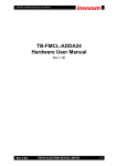
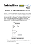
ECEN 5613
Fall 2015
Embedded System Design
Homework #1
Week #1
8/24/2015
NOTE: While a brief submission is acceptable, remember that every submission you make this
semester is an opportunity for you to demonstrate thoroughness and quality.
1. By 5:00pm on Friday, August 28th, e-mail a message to the instructor
(Linden.McCl [email protected]) with the subject line "ESDF15 HW #1". The instructor will
reply with a brief message so that you know your e-mail got to its destination. Answer the following
questions in the body of your e-mail (do not put your answers in an attachment):
(a) What is your Buff OneCard number? (this is not your student ID number)
(b) Do you have any preferred times/days for TA office hours?
(c) Do you have any preferred times/days for instructor office hours?
(d) Do you have access to a computer with webcam so that you can do video chat with the professor?
(e) If you have a job, what kind of work do you do for a living?
(f) Have you ever built an embedded system before? If yes, please list the microprocessor(s) and
programming language(s) you used.
(g) What was your favorite technical course in college and why?
(h) In which technical class in college did you learn the most and why?
(i) In your opinion, what are the characteristics of a good professor?
(j) What made you interested in this course?
(k) What do you want to gain from taking this course?
(l) Do you have the prerequisite hardware and software knowledge for this course? If your answer is
'no', what is your plan for successfully completing the course assignments?
(m) Do you have any concerns about this course? If so, please describe.
(n) Do you understand that this course has a significant workload? (Note: Students are advised not to
attempt ECEN 5613 and a heavy credit hour workload in the same semester, especially in their
first semester at CU.)
(o) In the event that a key lecture needs to be cancelled (e.g. for a blizzard, business travel, sickness,
etc.), what is your availability for a make-up lecture on a different day of the week?
•
•
•
•
Tuesday-Friday evening:
Saturday morning or afternoon:
Sunday afternoon:
Would you prefer to download a recorded make-up lecture and watch it off-line?
The following tasks will not be checked off and your answers to the questions will not be collected.
2. If you do not already have one, obtain a Buff OneCard, needed for access to the laboratory. BBA
students not seeking a degree can obtain a card for ~$25. For more information, see
https://services.jsatech.com/index.php?cid=59 .
3. Read the course syllabus and FAQ, available on the course web site.
4. Verify you can access the ECEN 5613 course page on Desire2Learn (D2L) https://learn.colorado.edu
5. Read the specified pages in the course documentation (also available from the course web site):
- "Siemens C501 Users Manual." Read sections 1–5. Skim the rest.
- "Siemens C500 Architecture and Instruction Set." Read sections 1–3. Skim the rest.
- "Siemens C501 Data Sheet." Skim pages 1–48.
- C501 Errata sheet
Additional documents have been placed on the course web site:
http://ecee.colorado.edu/~mcclurel/index.html
© 2004-2015 Linden H. McClure, Ph.D.
–1–
Embedded System Design
They contain similar information, but provide additional details you may find useful. Some of the
Philips (and Atmel) documents contain more detail and diagrams than the Siemens documents. Use
them in addition to the above documents if you like.
- "Philips 80C51 Family…80C51 Family Architecture." pp. 1-15.
- "Philips 80C51 8-bit Microcontroller Family Data Sheet." pp. 1–18, 22, 25, 26.
- "Philips 80C51 Family…80C51 Family Hardware Description." pp. 1–24.
- "Philips 80C51 Family…80C51 Family Programmer's Guide and Instruction Set." pp. 1–16.
6.
7.
If necessary, review your old course notes on digital logic, microprocessors, and circuits.
What is the address space of the 8051?
8.
9.
What is the purpose of the EA pin on the 8051?
What is the purpose of the ALE signal? How do you use this signal?
10. What is the purpose of
PSEN ?
11. In a system with external memory, for what purpose are ports P0 and P2 used?
12. Does the stack grow toward higher or lower memory in the 8051?
13. At what address is the reset vector located in the 8051? What constraint does this impose on the addition of
external memory for an 8031 which does not have internal ROM?
14. What interrupts are available on the 8051?
15. What memory locations do the interrupt vectors occupy, and why do you think they are spaced at 8-byte
intervals?
16. How many bytes of internal RAM are implemented in the 80C51? How about on the C501? Why is the
inclusion of RAM on a microcontroller important?
17. If the first instruction of my code was PUSH ACC (or PUSH A), what memory address would contain the
pushed copy of the accumulator?
18. For what purpose is DPTR used?
19. If I wanted to combine the external program and external data memory into one addressing space, what would I
have to do to the
PSEN and RD control signals?
20. In order to reset the processor, is it necessary to supply a logic high or a logic low voltage to the reset pin? Why
is a reset signal required? What is the minimum voltage required on the RST pin to hold the processor in reset?
What is the purpose of the diffused resistor inside the processor?
21. Review RC circuits. Now design an appropriate power on reset circuit for the 8051. Be prepared to discuss the
nuances of this circuit in depth. How does the threshold of the RST pin input impact your design? How do the
tolerances of resistors and capacitors impact your design? How does the tolerance of the power supply impact
your design?
22. Refer to videos on http://www.youtube.com and learn about wire wrapping. Note that the wire connecting any
two pins should have a small amount of slack, so that you can move the wire a little to aid in debugging if
necessary; however, there shouldn't be too much slack, since it will make the circuit more electrically noisy and
may be hard to debug. When stripping wire wrap wire, at least 3/4" (about 2 cm) of bare wire should be
showing. 0.75 inches is about this long:
23. Refer to the "Metcal Hand Soldering Basics" document on the course web site and review the basics of
soldering. Numerous soldering videos are also available on http://www.youtube.com. Other interesting web
sites containing soldering details can be found with a simple web search.
24. Obtain a suitable lab notebook. Your notebook will not be graded. Preferably, you should use a notebook with
sewn-in pages. Put your name in the book. You should use this notebook for embedded system notes and
designs during the semester. Document your work in ink and date each page as you use it. Number the pages in
your lab notebook from beginning to end. You may want to consider leaving the first page to use as a Table of
Contents. You can tape photocopies of data sheets (including pinouts, etc.) in your notebook for later reference.
During the course, document your discoveries and do your circuit designs and analysis work in the notebook.
Your notebook does not have to be a work of art, but it does need to be legible. Capture ideas as you think of
them—someday you may use your notebook to recall design details about your circuits. You may want to
capture most of your notes on the right-hand pages, and use the left-hand pages for drawings, photocopies, etc.
Your notebook is a good place to write down URLs for web pages containing good embedded systems info.
© 2004-2015 Linden H. McClure, Ph.D.
–2–
Embedded System Design
ECEN 5613
Fall 2015
Embedded System Design
Homework #2
Week #2
This assignment is due by the start of lecture on Week #2. Note: there is nothing to hand in for this
assignment. In this homework assignment, you will:
• Explore noise problems in microcontroller systems and how to address them
• Explore oscillators for microcontrollers
• Explore reset circuits and the effects of component tolerances on designs
• Explore power supply issues and microprocessor supervisory circuits
• Explore 8051 assembly code, the ASM51 assembler, and the Emily52 simulator
• Complete the software portion of Lab #1
Most of the assigned reading will be available on the course web site in PDF format.
1. If you do not already have an account on the ECES Student Server, visit http://eces.colorado.edu/ and
follow the instructions there to create your account. You will need your login in order to use the
computers in ECEE 1B28.
2. Download Lab #1 from the course web site and read it completely. Also download and review the
ECEN 5613 PCB Layout and Partial Schematics and Tips for Board Construction documents.
3. Read Intel application note AP-125 "Designing Microcontroller Systems for Electrically Noisy
Environments." Pay careful attention to the section on power supply distribution and decoupling.
4. [Optional] Read Intel application note AP-711 "EMI Design Techniques for Microcontrollers in
Automotive Applications". If you want extra detail, read Intel article reprint AR-533 "PC Layout
Techniques for Minimizing Noise". Note that typical values for chip decoupling capacitors are 0.1µF
or 0.01µF. This article is not available electronically, and will be made available in the lab.
5. Obtain a copy of the data sheet for the LM7805 (or LM340T5) linear regulator and read it. Make sure
you understand how to design a circuit for the regulator, and what requirements the regulator has
regarding input voltage level and maximum power dissipation.
6. Obtain a copy of the Intel application note AP-155 "Oscillators for Microcontrollers".
Read the following sections:
•
•
•
•
•
•
•
•
Page 1, Feedback Oscillators-Loop Gain
Page 2, How Feedback Oscillators Work, The Positive Reactance Oscillator (read the first paragraph)
Page 3, Quartz Crystals
Page 5, Frequency Tolerance
Page 6, Oscillator Design Considerations, On-Chip Oscillators
Page 7, Oscillation Frequency, Selection of CX1 and CX2
Page 13, Start-Up Characteristics
Page 15, Steady State Characteristics (read up to the Pin Capacitance paragraph)
7. While you're reading, answer the following questions (not to hand in). What are the definitions for the
terms frequency accuracy and frequency stability? In what kinds of microcontroller applications
would these two parameters be important, and why? How does the start-up of the oscillator impact
your reset circuit design? Additional information on crystals and oscillators is available at:
http://www.txccrystal.com/, http://www.foxonline.com, http://www.ecsxtal.com
8. Given a 10KΩ resistor with a tolerance of 5%, what range of resistance might you measure at 25°C?
9. Given a voltage divider (5% resistors) with R1=2KΩ connected to +5V and R2=3KΩ connected to
GND, what min and max voltages might be seen at the voltage divider output?
10. [Optional] Review the reset circuit design you developed for Homework #1. Taking into
consideration the internal diffused RRST resistor and VIH2, improve your design and specification.
Taking into account typical tolerances on your discrete components (assume +/- 10% for caps and +/5% for resistors), design a power-on reset circuit which will hold the 80C51 in reset for 20ms upon
power-on but is guaranteed to come out of reset within 80ms after power-on. You may assume that
© 2004-2015 Linden H. McClure, Ph.D.
–3–
Embedded System Design
11.
12.
13.
14.
15.
16.
17.
18.
19.
20.
21.
the diffused resistor inside the 80C51 has a worst case minimum value of 40KΩ and a worst case
maximum value of 225KΩ. Include a circuit which discharges your capacitor quickly in the event of a
temporary glitch in your power supply voltage. Assuming you have a momentary pushbutton switch
which has a max contact resistance of 100mΩ and a max current rating of 50mA at 5V DC, modify
your design to include a run-time reset circuit. Your design should include a circuit diagram,
component values, tolerances, a reset signal timing diagram, and mention of any other assumptions
you make. Prove that your circuit stays in reset for the required duration given worst case values of all
components. NOTE: This particular reset design is an exercise and is not required for Lab #1.
Briefly, how would your reset circuit change if you had a processor which was held in reset with a
low voltage on its reset line instead of a high voltage? Sketch your circuit, but don't worry about
supplying values for all your components.
Read Microchip application note AN686 "Understanding and Using Supervisory Circuits".
Skim the Microchip MCP-101 Microcontroller Supervisory Circuit data sheet.
Read the Maxim MAX691 data sheet. Design a resistive circuit to be connected to the PFI input of
the MAX691 which will trigger PFO if the supply voltage drops below 4.75V.
Which Maxim chip would you use to control the RST line of the 80C51? Why?
How does the MCP-101 compare in functionality to the MAX691? Why would you choose one
instead of the other?
Review the instruction set of the 8051. What are the main categories of instructions supported?
What is the difference between an AJMP and a LJMP assembly command? When might you want to
use one instead of the other?
For the next part, you will need to use the ASM51 assembler and the Emily52 simulator. You may
use the licensed tools installed on the computers in the lab, or you can obtain a copy of the Emily52
demo kit from the course web site. This demo kit includes a version of both the ASM51 assembler
and the Emily52 simulator, as well as a few simple example files. Note: You may need to install an
emulator like DOSBox to run these DOS tools under Windows 7/Vista. Note: It is also acceptable to
use an alternate simulator, such as EdSim51; however, the assignment below will assume Emily52.
Review the Emily52 presentation available on the course web site. Read the documentation for
ASM51 and Emily52. You will run these programs from within a DOS window. Understand the
command line options available for each software tool. Learn each of the assembler directives.
Review the test1.asm, test2.asm, and test3.asm files distributed with the demo version of Emily52.
Experiment with ASM51 and create full listing (.LST) files containing symbol information. Become
familiar with using the ORG and EQU directives. Assemble your code with a command line similar
to one of the following:
asm51 test1.asm -F
asm51 test1 -F -S
asm51 test1 -F -I
22. Examine the full listing file and verify the machine code generated by the assembler matches the
assembly code. Compare the output of the .hex file generated with and without the '-I' option.
23. Experiment with Emily52 and load a hex file created by ASM51. We will be using the 8051 with a
combined program and data space all semester; therefore, when you start Emily52, use the /Overlay
option when you load a hex record as shown: emily52 test1.hex /overlay
24. Understand how to control code execution and how to modify registers and memory. Explore the help
menu (F1) under the main screen and the help menu (F1) under the 'edit Data memory screen' (D).
25. Now, complete the software parts of Lab #1 (assembly code and simulator, SPLD). Get these
parts of the lab done early, so that you have more time to focus on hardware once you receive
your parts kit. Note that the course web site contains information in the "Course Archives:
Questions and Answers" links which can help you on Lab #1 and Lab #2.
© 2004-2015 Linden H. McClure, Ph.D.
–4–
Embedded System Design
ECEN 5613
Fall 2015
Embedded System Design
Homework #3
Week #3
This assignment should be completed by the start of lecture on Week #4. Note: there is nothing to hand
in for this assignment. In this homework assignment, you will explore:
• External memory interfacing (e.g. EPROMs and SRAMs)
• Logic families and programmable logic
The majority of the assigned reading will be available on the course web site in PDF format.
NOTE: You should always try to use the data sheet provided by the manufacturer of the exact part
that you are using in your circuits, since there can be differences between manufacturers of similar
chips—even standard chips, such as the 74LSxx TTL logic family members. If you cannot find the
correct data sheet, then you may need to look at the data sheet for a similar part/manufacturer.
1. Review the final project assignment, available from the course web site.
2. Review the current topics presentation assignment, available from the course web site.
3. Read pages 1–18 of Philips application note AN457 "80C51 External Memory Interfacing". While
you're reading it, keep in mind that the processor on the board that you will build will be running at
11.0592MHz, a significantly lower speed than 33MHz. Take time to understand the timing diagrams
and what each of the minimum and maximum timing specifications really means. Take a few minutes
and review the timing diagrams in the C501 or 80C51 product specification. Remember that during a
read cycle, the peripheral chip (EPROM or SRAM) is driving the data bus, while during a write cycle,
the processor is driving the data bus.
4. Obtain and read the following EPROM-related documents:
• Data sheet for an EPROM, including the AMD Am27C256 (32Kx8) or Fairchild FM27C256
EPROM.
• Technical note "Programming AMD's CMOS EPROMs"
Determine how you would hook up an EPROM to the 80C51. Get a basic understanding for how
EPROMs work, and how you would program and erase an EPROM. Think about how would you
design a circuit to program an EPROM.
5. Obtain and skim a data sheet for your SRAM on the course web site. Your SRAM may be one of
several types, including the TI BQ4011 NV-SRAM, Cypress CY62256 (32Kx8), Hitachi 62256,
Samsung K6T0808C1D, or Winbond W24257 SRAM. Determine how to hook it up to the 80C51.
Compare the SRAM and EPROM pinouts. Note that we use the 28-pin DIP package in this class.
6. What could happen if you leave the /WE pin on the NV-SRAM floating (not connected)?
7. Understand how each of the following LS TTL chips works. The data sheets are available on the
course web site, but you may also want to store them on a USB drive key, floppy disk or on your PC.
•
74LS00, 74LS02, 74LS04, 74LS08, 74LS74, 74LS138, 74LS156, 74LS244, 74LS245, 74LS373, 74LS374
The On Semiconductor LS TTL General Data document includes interesting technical information.
8. How is 'noise margin' associated with the following logic gate specifications: VOH, VOL, VIH, VIL?
9. Does a TTL totem pole output sink or source current?
10. When a logic high is applied to a TTL gate input, is the input sinking or sourcing current?
11. When a logic low is applied to a TTL gate input, is the input sinking or sourcing current?
12. What is 'fanout' and how does that relate to VOH and VOL?
13. Read about the Atmel ATF16V8C SPLD (programmable logic). Read about WinCUPL. Documents
and links are available on the course web site.
14. Is a decoupling capacitor required when using an EPROM? How about when using an NV-SRAM?
© 2004-2015 Linden H. McClure, Ph.D.
–5–
Embedded System Design
15. What is the difference between an OTP EPROM and a UV EPROM?
16. Do more standard values exist for resistors or for capacitors? How might this impact your use of these
components in designs?
17. Why should components be derated when used in circuits? Suppose you have a capacitor that has a
working voltage of +10V. What maximum operating voltage should be applied to this capacitor for
extended periods of time?
18. Suppose you have an RC circuit consisting of a 5% 100KΩ resistor and a 10% 5uF capacitor. What is
the maximum and minimum time constant of this circuit at 25°C?
19. How does the temperature characteristic or profile of a resistor or capacitor affect its operation? Take
a look at the temperature characteristic for an electrolytic capacitor (shown below) and determine
how the component's value changes when operating at 100°C.
+10%
000
-10%
-20%
-30%
-50°°C
+25°°C
+100°°C
20. How do the characteristics of an X7R capacitor compare with a Z5U capacitor?
21. [Optional] Review a logic book or visit a web site such as one of the following and explore logic
families. While you're at the chosen web site, explore a little and try to understand some of the
differences between the different logic families (e.g. LS, S, ALS, FAST, HCT, etc.). Note the
differences in supply voltages, and input and output voltages of some of the different devices. Using
the information from the data sheets or from a text book, compare the fanout, propagation delays,
signal transition times, and power consumption of at least three of the families. Think about the
advantages and disadvantages of using each of the particular families you examined.
• Texas Instruments: http://focus.ti.com/general/docs/scproducts.jsp
• Texas Instruments: http://focus.ti.com/lit/ml/sdyu001z/sdyu001z.pdf
• ON Semiconductor: http://www.onsemi.com/PowerSolutions/ (formerly Motorola logic)
• Toshiba: http://www.toshiba.com/taec/ (see Products > Logic ICs)
• NXP: http://www.nxp.com/products/logic/
• Fairchild: https://www.fairchildsemi.com/products/logic/
For a list of logic manufacturers, see: http://www.interfacebus.com/Standard_Logic.html
© 2004-2015 Linden H. McClure, Ph.D.
–6–
Embedded System Design
ECEN 5613
Fall 2015
Embedded System Design
Homework #4
Week #4
This assignment should be completed by the start of lecture on Week #5. Note: there is nothing to hand
in for this assignment; however, you will use a memory map like this (with some modifications) for
Labs 2-4. In this homework assignment, you will explore:
• Memory Maps. Glue Logic, Programmable Logic.
1. Review class notes and information on the web regarding memory maps and chip select (glue) logic.
2. Design glue logic for your 8051 board which supports the following memory map: Your code storage
device (EPROM or NV-SRAM) must be located starting at address 0000h and must occupy 32KB of
address space (addresses 0000h-7FFFh). A 32KB SRAM must be located starting at address 8000h
and must occupy 28KB of address space (addresses 8000h-EFFFh). Note: The upper 4KB of the
32KB SRAM will not be used. The next 4KB of address space (addresses F000H-FFFFh) should be
used for peripherals, which you will add later in the semester. Your decode logic should generate a
chip select signal for the EPROM, a chip select for the SRAM, and a chip select for peripherals. Use a
combined program and data space for the SRAM by ANDing the PSEN and RD lines to create a
READ signal for the SRAM /OE pin. Options for your decode logic include the Atmel ATF16V8C
SPLD (programmable logic), discrete logic, a 74LS138, or a 74LS156. Use a 74LS373 to demultiplex
the 8051 address/data bus. If you choose to use a fast '245 transceiver to buffer Port 0, you can use the
READ signal to control the direction of data flow through the transceiver.
Increasing
Addresses
Address in Binary
1111xxxxxxxxxxxx
1110xxxxxxxxxxxx
1101xxxxxxxxxxxx
1100xxxxxxxxxxxx
1011xxxxxxxxxxxx
1010xxxxxxxxxxxx
1001xxxxxxxxxxxx
1000xxxxxxxxxxxx
0111xxxxxxxxxxxx
0110xxxxxxxxxxxx
0101xxxxxxxxxxxx
0100xxxxxxxxxxxx
0011xxxxxxxxxxxx
0010xxxxxxxxxxxx
0001xxxxxxxxxxxx
0000xxxxxxxxxxxx
Hex
F000-FFFFh
EFFFh
Address Use
Peripherals (4KB)
External SRAM
(XRAM)
(28KB)
64 KB of
Address
Space
8000h
7FFFh
EPROM/Flash
(32KB)
(non-volatile memory)
0000h
3. Read more about the Atmel ATF16V8C SPLD and Atmel WinCUPL. Documents and links are
available on the course web site. Note that the WinCUPL software supports a very easy syntax for
assigning a range of addresses to a chip select signal.
4.
[Optional] Visit the web and learn about GAL/PLD technology (see the GAL20V8 and ispGAL22V10) and
CPLD technology. Visit the Xilinx web site ( http://www.xilinx.com ). Learn the basics of how the Xilinx FPGA
technology works. Visit the web sites for Actel ( http://www.actel.com ) and Altera ( http://www.altera.com ), and
understand how their technologies work.
5. [Optional] Search the Internet for web sites with good application notes or technology articles on at least two of
the programmable logic technologies listed above. If you find any very good sites, send an e-mail message
containing the URLs along with a short clearly-written synopsis of each web site to your instructor at
Li n de n.M cCl ur e@ Co lo ra do . E DU. The URLs should be fully qualified: use http:// in each URL, so
that one can click on the URL in your e-mail to go immediately to that web site.
© 2004-2015 Linden H. McClure, Ph.D.
–7–
Embedded System Design
ECEN 5613
Fall 2015
Embedded System Design
Homework #5
Week #4
This assignment should be completed by the start of lecture on Week #5. Note: there is nothing to hand
in for this assignment. In this homework assignment, you will explore:
• Timing
•
Logic Analyzers
•
I/O ports
•
Course web site
• Memory
The assigned reading will be available on the course web site in PDF format.
1. Read the handout from class "Understanding Timing Diagrams and the C501 Data Sheet".
2. Why are the setup and hold times for chips important?
3. Suppose you're examining the interface between a processor and an EPROM/NVRAM (or
other non-volatile device used for code storage).
a) Why is the access time of the EPROM/NVRAM important?
b) Why is the float time of the EPROM/NVRAM important?
c) What is bus contention or "drive fight"?
d) Why must the bus cycle timing in a design be verified if the processor crystal frequency
is changed?
4. Read Agilent Application Note 1337 "Feeling Comfortable with Logic Analyzers", available
on the course web site (or from http://www.keysight.com).
5. Read the "Agilent/HP 1662A Logic Analyzer Notes" document available on the course web
site.
6. Read the "Intronix LA1034 LogicPort Logic Analyzer Notes" document available on the
course web site.
7. Download the Intronix LogicPort logic analyzer software from the Intronix web site
(http://www.intronix.com), and become familiar with its capabilities.
8. If you haven't completed your wire wrapping for Lab #2, finish that immediately, since
Lab #2 is more time consuming than Lab #1.
9. Read section 6.1 of the C501 User's Manual regarding the I/O port circuitry.
10. If you haven't done so already, go to the course web site and read the various pages in the
Questions and Answers sections.
11. [Optional] Review some of the Memory Technology links available on the course web site.
© 2004-2015 Linden H. McClure, Ph.D.
–8–
Embedded System Design