1
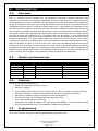
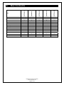
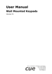
User Manual
ipCUE Controllers
Version 02
CUE, a.s., K Nouzovu 6, 143 00 Praha 4, Czech Republic
Phone: +420 241 091 240, Fax: +420 241 432 446
www.cuesystem.com, [email protected]
User Manual ipCUE Controllers
UM028_02, 22.12.2006
Copyright © CUE, a.s., Praha, Czech Republic 1990 - 2006.
All rights reserved. Specifications are subject to change without prior notice.
1.
Table of Contents
1.
Table of Contents........................................................................................................................... 3
2.
Introduction .................................................................................................................................... 5
2.1.
2.2.
2.3.
2.4.
Overview .................................................................................................................................................5
Models and Accessories .........................................................................................................................5
Features ..................................................................................................................................................5
Programming...........................................................................................................................................5
3.
Box Contents.................................................................................................................................. 6
4.
Specifications................................................................................................................................. 7
5.
Quick Start ...................................................................................................................................... 8
5.1.
5.2.
5.3.
5.4.
Powering Up............................................................................................................................................8
PC Connection ........................................................................................................................................8
Windows XP Local Area Connection Settings ....................................................................................... 10
Access Admin Web Server.................................................................................................................... 11
6.
Front Panels ................................................................................................................................. 12
7.
Indicators ...................................................................................................................................... 13
7.1. PWR Indicator .......................................................................................................................................13
7.2. LINK Indicator........................................................................................................................................13
7.3. ACT Indicator ........................................................................................................................................13
7.4. CPU Indicator ........................................................................................................................................13
7.5. IR SENSOR ..........................................................................................................................................13
7.6. SERIAL Port Indicator ...........................................................................................................................14
7.7. IR/SERIAL Output Indicator ..................................................................................................................14
7.8. GENERAL I/O Indicator.........................................................................................................................14
7.9. AUX Indicator ........................................................................................................................................14
7.10. ANALOG Output Indicator .....................................................................................................................14
8.
Rear Panels................................................................................................................................... 15
9.
Connection ................................................................................................................................... 16
9.1. CUEnet (LAN) .......................................................................................................................................16
9.2. PWR IN .................................................................................................................................................17
9.3. CUEwire ................................................................................................................................................17
9.4. OUT 5 V ................................................................................................................................................17
9.5. SERIAL 1 – 2 ........................................................................................................................................18
9.6. SERIAL 3 – 6 ........................................................................................................................................19
9.7. IR/SERIAL Output .................................................................................................................................21
9.8. GENERAL I/O .......................................................................................................................................22
9.9. AUX (Low Voltage Relay)......................................................................................................................23
9.10. ANALOG Output....................................................................................................................................23
10. System Connection ..................................................................................................................... 24
10.1. CUEwire ................................................................................................................................................24
10.2. CUEring.................................................................................................................................................26
11. Mounting ....................................................................................................................................... 27
11.1. Shelf Placement or Stacking .................................................................................................................27
11.2. Rack Mounting ......................................................................................................................................28
12. FACTORY DEFAULT Button ....................................................................................................... 29
13. Admin Web Server ....................................................................................................................... 30
13.1. Login .....................................................................................................................................................30
13.2. Configuration .........................................................................................................................................31
13.3. Date and Time.......................................................................................................................................32
13.4. Applications ...........................................................................................................................................33
13.5. File Storage ...........................................................................................................................................34
13.6. Web Storage .........................................................................................................................................35
13.7. Diagnostics............................................................................................................................................36
User Manual ipCUE Controllers
www.cuesystem.com
Page 3 of 48
13.8. E-mail ....................................................................................................................................................37
13.9. System ..................................................................................................................................................38
13.10. Password ...........................................................................................................................................39
13.11. Backup ...............................................................................................................................................40
13.12. Reset ..................................................................................................................................................41
13.13. Logout ................................................................................................................................................42
13.14. License ...............................................................................................................................................43
14. Software and Firmware License................................................................................................. 44
15. Warranty Conditions.................................................................................................................... 45
16. CE Declaration of Conformity..................................................................................................... 46
17. FCC................................................................................................................................................ 47
18. Notes ............................................................................................................................................. 48
User Manual ipCUE Controllers
www.cuesystem.com
Page 4 of 48
2.
Introduction
2.1.
Overview
CUE, a.s. unveils the ipCUE controllers as a new generation of Ethernet IP enabled controllers. These
controllers are well suited for single-room applications as well as huge multi-room, multi-floor distributed
control applications. The ipCUE controllers come with multiple control ports well suited for home applications
as well as commercial. The control ports include bi-directional serial ports RS-232, bi-directional serial ports
configurable as RS-232, RS-422, or RS-485, infrared outputs up to 1.2 MHz that can be configured to control
up to three pieces of equipment, general I/O ports that can also be configured as analog inputs and 24 volts
relay outputs. The Ethernet port allows for bi-directional IP control of any manufacturer IP enabled products.
The ipCUE controllers are compatible with CUE‘s existing range of button panels and touch panels through
and come equipped with a CUEwire port. For convenience there has also been a +5 VDC output added to
the design for powering external low-voltage equipment. The units are equipped with internal IR sensor
(except ipCUE-gamma). The sensor allows capture IR codes and links IR wireless control panels.
Convenient for testing and troubleshooting the ipCUE controllers also come with indicator LEDs on the front
panel that indicates the status of all of the control ports. The ipCUE controllers keep perfect time with its
onboard real time clock (RTC) and thus allowing for a wide variety of distributed intelligence scheduling
applications. The ipCUE controllers come complete with a web-server and allow for setup, configuration, and
testing through a standard web browser. This web-based interface allows for the graphical monitoring and
control of all ports, which provides a truly timesaving method for testing and troubleshooting.
2.2.
Models and Accessories
Model
Product code
Description
ipCUE-alpha
CS0251
IP based controller
ipCUE-beta
CS0252
IP based controller
ipCUE-gamma
CS0253
IP based controller, DIN rail mounting
ipCUE-delta
CS0267
IP based controller
ipCUE-epsilon
CS0268
IP based controller
CS0251-MR
Rack 19” mounting kit (sold separately)
2.3.
Note
Features
The main features of the controllers are
• Based on the Motorola ColdFire® processor
• Ethernet IP enabled
• Fully compatible with current CUE communication buses – CUEnet, CUEwire, CUEring and PEbus
• Standard control ports - bi-directional serial, IR/serial, general I/O, analog and relay ports.
• Web server complete with Admin web pages for setup and diagnostics
• XPL Runtime inside, fully compatible with CUE programming tools
• Front panel indicators for each control port
• Unified enclosure design for desktop, rack, DIN rail and wall installation - no special models required
• DIN rail, wall installation and 19" rack installation available with accessories
2.4.
Programming
The ipCUE controllers are programmed using Cue Director programming tools.
User Manual ipCUE Controllers
www.cuesystem.com
Page 5 of 48
ipCUE-beta
ipCUE-gamma
ipCUE-delta
ipCUE-epsilon
Box Contents
ipCUE-alpha
3.
ipCUE-alpha
ipCUE-beta
ipCUE-gamma
ipCUE-delta
ipCUE-epsilon
1 set
1 set
1 set
1 set
1 set
IR Adapter /i
4
4
2
8
4
Ethernet cable
1
1
1
1
1
Ethernet cable cross
1
1
1
1
1
CUEadapter /30W
1
1
1
-
1
CUEadapter /65W
-
-
-
1
-
Power Cable
1
1
1
1
1
CE declaration
1
1
1
1
1
RoHS declaration
1
1
1
1
1
Controller data sheet
1
1
1
1
1
Cue System Connector Wiring
1
1
1
1
1
CD User Manuals
1
1
1
1
1
Item
Controller
Connector Set
User Manual ipCUE Controllers
www.cuesystem.com
Page 6 of 48
4
-
-
4
-
8
8
2
8
8
8
-
8
8
8
2
-
2
16
8
-
-
-
4
4
1
1
-
1
1
1
1
-
1
1
ipCUE-gamma
ipCUE-epsilon
Ethernet connection
10/100 BaseT LAN, RJ-45 connector
System connection
CUEwire (RS-485) for control panels,
dedicated 4-pin connector 5 mm
CUEring (RS-232) for interfaces,
bi-directional serial channel
PEbus (RS-485) for power and lighting
control, bi-directional serial channel
Control ports
Bi-directional serial RS-232,
5-pin connector 3.5 mm
Bi-directional serial RS-232/422/485,
5-pin connector 3.5 mm
IR/serial output, IR output up to 1.2 MHz,
2-pin connector 3.5 mm
General I/O input (analog 0 - 5 V) or
output (open collector max. 80 mA),
2-pin connector 3.5 mm
Relay 24 V / 0.5 A,
3-pin connector 3.5 mm
Analog output 0 – 10 V,
2-pin connector 3.5 mm
Power output 5 VDC (max. 1 A),
2-pin connector 3.5 mm
Internal IR sensor for IR code capture and
for IR wireless control panel link
LED indicators
Button Factory default settings
Real time and date - RTC with battery backup
Memory
Software
Power supply, 2-pin connector 5 mm
Power consumption
Enclosure
Dimensions (WxHxD) in mm
Weight
ipCUE-beta
Feature
ipCUE-delta
Specifications
ipCUE-alpha
4.
1
1
1
1
2
Power, CUEnet, Data, All control ports
1
1
Internal RAM 16 MB, Flash 4 MB (16 MB from 2007)
XPL Runtime, Admin web
24 VDC (+/-20%)
12 W
10 W
10 W
18 W
15 W
Metal
Metal
Plastic
Metal
Metal
210 x 43.5 x 92
210 x 43.5 x 92
106 x 90 x 58
422 x 43.5 x 92
210 x 43.5 x 92
0.6 kg
0.5 kg
0.4 kg
0.8 kg
0.6 kg
User Manual ipCUE Controllers
www.cuesystem.com
Page 7 of 48
5.
5.1.
Quick Start
Powering Up
Every ipCUE controller requires a power from an external power supply. The standard CUEadapter /30W or
CUEadapter /65W is delivered with the unit. Attach the 2-pin connector of the power supply unit to the PWR
IN connector located on the rear panel of ipCUE controller and attach power cable to a power outlet. The
LED labeled PWR will light up when the unit is powered on.
5.2.
PC Connection
Using LAN Directly to PC
Attach one end of an RJ-45 Ethernet cross-over cable to the ipCUE controller CUEnet (LAN) port and
attach the other end to the RJ-45 Ethernet cable to your computer.
Ethernet Cross-Over Cable
This cable can be used to cascade hubs, or for connecting two Ethernet stations back-to-back without a hub.
It works with 10Base-T, 100Base-TX, 100Base-T4 and 1000Base-T. Use a good enough cable, if you are
confused about categories of cables then use Category 5 (enhanced) and you'll be fine even at 1000Base-T.
1
8
Top
1
8
1
8
Top
Front
Front
1
8
To Network Interface Card 2 (NIC 2)
Touch panel
RJ45 Male Connector
To Network Interface Card 1 (NIC 1)
Computer
RJ45 Male Connector
Name
NIC 1
Color
NIC 2
Name
TX+ (BI_DA+)
1
White/Orange
3
RX+ (BI_DB+)
TX- (BI_DA-)
2
Orange
6
RX- (BI_DB-)
RX+ (BI_DB+)
3
White/Green
1
TX+ (BI_DA+)
- (BI_DC+)
4
Blue
7
- (BI_DD+)
- (BI_DC-)
5
White/Blue
8
- (BI_DD-)
RX- (BI_DB-)
6
Green
2
TX- (BI_DA-)
- (BI_DD+)
7
White/Brown
4
- (BI_DC+)
- (BI_DD-)
8
Brown
5
- (BI_DC-)
That means that the White/Orange cable connected to NIC 1 pin 1 should go to NIC 2 pin 3 and NIC 1 pin 2
to NIC 2 pin 6 etc.
User Manual ipCUE Controllers
www.cuesystem.com
Page 8 of 48
Notes
1. 1000Base-T names are in parentheses.
2. It's important that each pair is kept as a pair. TX+ & TX- must be in the pair and RX+ & RX- must
together in another pair. Just as the table above shows.
3. While 10Base-T and 100Base-TX only uses 2 pairs, please connect all four since 100Base-T4 and
1000Base-T needs them and save you some future debugging.
4. The colors originate from the numbering and name on NIC 1.
5. The connection is based on IEEE Standard 802.3, 2000 Edition.
Using LAN Network
Attach one end of an RJ-45 Ethernet straight through cable to the ipCUE controller CUEnet (LAN) port and
attach the other end to the RJ-45 Ethernet cable to your computer.
User Manual ipCUE Controllers
www.cuesystem.com
Page 9 of 48
5.3.
Windows XP Local Area Connection Settings
Steps are
1. Start Windows XP.
2. Click Start, then click Control Panel choose the option to switch to Classic View.
3. Double-click Network Connections, select the Local Area Connection and then right-click and select
Properties.
4. Select Internet Protocol (TCP/IP) and click Properties button.
User Manual ipCUE Controllers
www.cuesystem.com
Page 10 of 48
5. Select Use the following IP address option. Set IP address to 192.168.1.1 (or other address different
from 192.168.1.128) and Subnet mask to 255.255.255.0. Leave other options unchanged and click
OK.
5.4.
Access Admin Web Server
Run the Internet Explorer on your PC and type in the ipCUE factory default IP address 192.168.1.127. The
Admin login web page will be displayed. The password is set to default.
User Manual ipCUE Controllers
www.cuesystem.com
Page 11 of 48
6.
Front Panels
The ipCUE-alpha, ipCUE-beta, ipCUE-delta and ipCUE-epsilon front panels are made of aluminum plate.
The ipCUE-beta front panel is made of plastic. It should be cleaned with a soft/non-abrasive cloth. The
indication LEDs and infrared sensors are behind the front panel.
ipCUE-alpha
ipCUE-gamma
ipCUE-beta
ipCUE-epsilon
ipCUE-delta
User Manual ipCUE Controllers
www.cuesystem.com
Page 12 of 48
7.
7.1.
Indicators
PWR Indicator
Off ............................................. No power presented.
On ............................................. Power 24 V is presented. The unit is ready.
7.2.
LINK Indicator
Off ............................................. Network is not detected.
On ............................................. Network detected.
7.3.
ACT Indicator
Off ............................................. No data transmitted or received through the CUEnet (LAN) port.
On or Flashing .......................... Data is being transmitted or received through the CUEnet (LAN) port.
7.4.
CPU Indicator
This LED indicates the end of the operating system boot up by flashing OK in Morse code. Operating system
is booted after the unit has either been reset or switched on. The booting time is approx. 13 seconds.
7.5.
IR SENSOR
The window marked by IR SENSOR (not applied in ipCUE-gamma), covers two IR sensors and one LED
indication.
1. The first built-in IR sensor carries the same functionality as irCUE Receiver or irCUE Receiver 485.
This means that ipCUE can receive IR signal from CUE wireless IR control panels without the need
to use any external IR receiver.
2. The second built-in IR sensor allows IR codes capture directly by ipCUE unit. The flashing Yellow
LED indicates the received infra-red signal and serves for optimum distance setup between the
receiver and captured IR remoter.
User Manual ipCUE Controllers
www.cuesystem.com
Page 13 of 48
7.6.
SERIAL Port Indicator
Off ............................................. No data transmitted or received through the serial port.
Green On or Flashing............... Data is being transmitted through the serial port.
Red On or Flashing .................. Data is being received through the serial port.
Note: The S1 serial channel is used as CUEring port for interfaces and power and lighting control units.
7.7.
IR/SERIAL Output Indicator
Off ............................................. No data or IR code transmitted through the IR/serial port.
On or Flashing .......................... Data or IR code is being transmitted through the IR/serial port.
7.8.
GENERAL I/O Indicator
Off ............................................. Output is switched OFF.
On ............................................. Output is switched ON.
7.9.
AUX Indicator
Off ............................................. AUX (relay) is switched OFF.
On ............................................. AUX (relay) is switched ON.
7.10.
ANALOG Output Indicator
Off ............................................. Analog output is set to 0 V.
On ............................................. Analog output is set to 10 V.
User Manual ipCUE Controllers
www.cuesystem.com
Page 14 of 48
8.
Rear Panels
Connectors and button are located on the rear panel of the device. All connectors are labeled incl. pin out.
ipCUE-alpha
ipCUE-gamma
ipCUE-beta
ipCUE-epsilon
ipCUE-delta
User Manual ipCUE Controllers
www.cuesystem.com
Page 15 of 48
9.
Connection
9.1.
CUEnet (LAN)
The CUEnet is a standard network connection 10/100 BaseT LAN using RJ-45 connector. There is no auto
sense that means it does not recognize straight through cable to cross-over cable. For the direct PC
connection it is necessary to use cross-over cable; for the connection to Ethernet switch straight through
cable. The length of the Ethernet cable connecting ipCUE controller to the network must not exceed 100
meters.
Connector pin out
RJ-45
8
1
Pin
1
2
3
4
5
6
7
8
CUEnet (LAN)
Signal
Description
TX_D1+
TX_D1RX_D2+
RX-D2G
G
Ground
Ground
User Manual ipCUE Controllers
www.cuesystem.com
Page 16 of 48
Cat5 Cable Color
White / Orange
Orange
White / Green
Blue
White / Blue
Green
White / Brown
Brown
9.2.
PWR IN
Warning: Use any ipCUE controller only with the power adapter supplied in the product package. Using
another power supply may damage the unit.
Connector pin out
2-pin 5 mm
+
9.3.
Pin
G
PWR IN
Description
+
Power +24 VDC
G
Ground
CUEwire
Connector pin out
4-pin 5 mm
+24
9.4.
G
A+
B-
Pin
1
2
3
4
Signal
+24
G
A+
B-
CUEwire
Description
Power +24 VDC
Ground
RS-485 Data +
RS-485 Data -
OUT 5 V
Connector pin out (not applied in ipCUE-gamma)
2-pin 3.5 mm
+ G
Pin
OUT 5 V
Description
+
Output +5 VDC, max. 1 A
G
Ground
User Manual ipCUE Controllers
www.cuesystem.com
Page 17 of 48
9.5.
SERIAL 1 – 2
These two bi-directional serial channels are used for RS-232 communication. Maximum speed is 115 200 Bd
(bps). Transmission levels for RS-232 output are in the -12 V to +12 V.
Connector pin out
5-pin 3.5 mm
1 2 3 4 5
Pin
1
2
3
4
5
Signal
TxD
RTS
GND
RxD
CTS
RS-232
Description
RS-232 Transmitted Data
RS-232 Request to Send
Ground
RS-232 Received Data
RS-232 Clear to Send
Direction
From ipCUE
From ipCUE
To ipCUE
To ipCUE
Note: The S1 serial channel is used as CUEring port for interfaces and power and lighting control units.
User Manual ipCUE Controllers
www.cuesystem.com
Page 18 of 48
9.6.
SERIAL 3 – 6
Overview
These four bi-directional serial channels (ipCUE-alpha, ipCUE-delta only) are used for RS-232, RS-422 and
RS-485 communication. Maximum speed is 115 200 Bd (bps). Default mode for all channels is RS-232,
other modes must be set in programming application or by Admin Web. For more details about Admin Web
see in the chapter Admin Web Server.
Channel Mode Setting
It is important to set channel mode in the programming application. The mode is selected by part of mode
string in the command CommunicationSet.
Command example in XPL language for 9600 bd, non parity and 1 stop bit is as follows
•
ipCUE_alpha.S3.CommunicationSet (“0096008n1m232”)
for RS-232 mode (default)
•
ipCUE_alpha.S3.CommunicationSet (“0096008n1m422”)
for RS-422 mode
•
ipCUE_alpha.S3.CommunicationSet (“0096008n1m485”)
for RS-485 mode
For more details see programming manuals.
RS-232 Mode
Transmission levels for RS-232 output are in the -10 V to +10 V.
This is default mode for all channels. If a channel was set to other mode, it is possible to use XPL command
ipCUE_alpha.S3.CommunicationSet (“0096008n1m232”).
Connector pin out
5-pin 3.5 mm
1 2 3 4 5
Pin
1
2
3
4
5
Signal
TxD
RTS
GND
RxD
CTS
RS-232
Description
RS-232 Transmitted Data
RS-232 Request to Send
Ground
RS-232 Received Data
RS-232 Clear to Send
User Manual ipCUE Controllers
www.cuesystem.com
Page 19 of 48
Direction
From ipCUE
From ipCUE
To ipCUE
To ipCUE
RS-422 Mode
Only channels S3 – S6 can be used in the RS-422 mode.
This mode must be set in the programming application or by Admin Web. The right command in XPL is
ipCUE_alpha.S3.CommunicationSet (“0096008n1m422”).
Connector pin out
5-pin 3.5 mm
1 2 3 4 5
Pin
1
2
3
4
5
Signal
Tx A+
Tx BGND
Rx A+
Rx B-
RS-422
Description
RS-422 Transmit Data (Idles High)
RS-422 Transmit Data (Idles Low)
Ground
RS-422 Receive Data (Idles High)
RS-422 Receive Data (Idles Low)
Direction
From ipCUE
From ipCUE
To ipCUE
To ipCUE
RS-485 Mode
Only channels S3 – S6 can be used in the RS-485 mode.
This mode must be set in the programming application or by Admin Web. The right command in XPL is
ipCUE_alpha.S3.CommunicationSet (“0096008n1m485”).
Connector pin out
5-pin 3.5 mm
1 2 3 4 5
Pin
1
2
3
4
5
Signal
A+
BGND
N.C.
N.C.
RS-485
Description
RS-485 Data +
RS-485 Data Ground
Not Connected
Not Connected
User Manual ipCUE Controllers
www.cuesystem.com
Page 20 of 48
9.7.
IR/SERIAL Output
IR/Serial output labeled IR/SERIAL 1 – 8 (ipCUE-alpha, ipCUE-beta, ipCUE-delta, ipCUE-epsilon) or
IR/SERIAL 1 – 2 (ipCUE-gamma) provides output for infra-red emitters (IR Adapter /i) or eight RS-232 serial
outputs (one way). Maximum IR output rate is 1.2 MHz, maximum serial data rate is 115 200 Bd (bps).
Transmission levels for RS-232 output are in the -12 V to +12 V. The IR outputs and RS-232 outputs can be
combined on independent outputs (for example three outputs can be used as IR, five outputs can be used as
RS-232).
Connector pin out
2-pin 3.5 mm
IR/Serial
Pin
Description
S G
S
IR/Serial Signal (Output)
G
Ground
Note: All pins labeled G are connected together.
Note: Up to three original infra-red emitters IR Adapter /i can be connected to each output in parallel. Finally
it allows to control up to 24 IR controlled devices.
Note: It is not suggested to connect more infra-red emitters of various manufacturers in parallel because the
output can be either overloaded or damaged.
User Manual ipCUE Controllers
www.cuesystem.com
Page 21 of 48
9.8.
GENERAL I/O
General IO labeled GENERAL I/O 1 - 8 (not applied in ipCUE-beta) provide analog input as well as digital
output. Each general I/O port can be used either as input or as output.
Analog input is rated 0 – 5 VDC, digital output offers 80 mA. Pull-up resistor 680 ohms connected to +5 VDC
can be switched on and off for each IO independently. Input voltage with pull-up on is approx. 4.3 VDC,
because protection diode is connected in series (0.7 V drop-down). Output voltage for output switch on is
approx. 0.6 V. Analog to digital (A/D) converter has 10-bits precision (i.e. 1024 levels).
IO schematic diagram
ipCUE Controller
+5 VDC
ON
OFF
PULLUP
value ON / OFF
A
0 - 5 VDC
1k
D
I/O
INPUT
value 0 - 1023
10 bit
Input/output
IO
value ON / OFF
Ground
Connector pin out
2-pin 3.5 mm
General IO
Pin
Description
S G
S
Input/Output Signal
G
Ground
Note: All pins labeled G are connected together.
User Manual ipCUE Controllers
www.cuesystem.com
Page 22 of 48
9.9.
AUX (Low Voltage Relay)
This connector labeled AUX 1 – 2 (ipCUE-alpha, ipCUE-gamma) or AUX 1 – 8 (ipCUE-epsilon) or AUX 1 –
16 (ipCUE-delta) provides one isolated low voltage relay. Normally Close and Normally Open contacts as
well as Common contact of each relay can be used. The Normally Close position is the state of the relay
when it is not turned on (energized). Each relay contact closure is rated 24 V / 0.5 A.
Connector pin out
3-pin 3.5 mm
Aux (Low Voltage Relay)
Pin
Description
NC
C
NC C NO
9.10.
NO
Aux Contact Normally Close
Aux Contact Common
Aux Contact Normally Open
ANALOG Output
Analog output labeled ANALOG 1 - 4 (ipCUE-delta and ipCUE-epsilon only) provides analog output 0 - 10 V.
When connecting with another device (e.g. dimmer) it is essential to see to a perfect interconnection with
earth. The output voltages generated by the analog output is mutually related to the reference level (ground)
on pin labeled G.
Parameters of the analog output
• Range of the output voltage
• Max. output current (both source and sink)
• Stepping regulation (LSB)
• Min. set-up precision
0 - 10 V
10 mA
39 mV
± 0.08 V (± 2 LSB)
Connector pin out
2-pin 3.5 mm
Analog Output
Pin
Description
S G
S
Analog Output Signal 0 - 10V
G
Ground
Note: All pins labeled G are connected together.
User Manual ipCUE Controllers
www.cuesystem.com
Page 23 of 48
10. System Connection
10.1.
CUEwire
CUEwire Installation
On the picture you can see a typical connection of CUEwire.
Controller
CUEwire 4-pin Connector
GND
+ 24 VDC
External power
supply
1
2
3
4
+ 24 VDC
GND
120 ohm
A+
B-
4-pin
4-pin
4-pin
Control Panel n
Control Panel 2
Control Panel 1
The cable consists of 4 wires. The first pair serves as a signal line. The second pair of wires serves for power
distribution. The signal conductors can have minimal 0,25 mm2, capacity maximal 100 pF/m.
The power distribution cable design depends on number of control panels to be connected and on the
required length of the cable. The maximum voltage loss on the whole power distribution conductors should
not exceed 4 V on the ground wire and 4 V on the +24 V wire.
To supply power distribution line the output OUT of the controller can be used. In this case the whole
consumption should not exceed 2 A. In case of using more than 2 touchCUEs units or for longer distances it
is necessary to use external power supply +24 V for remote panels (see example of the Panel n in the
picture above).
Approximate consumption of control panels is
touchCUE ....................... 1.0 A
keyboardCUE ................. 0.3 A
keyboardCUE-S.............. 0.1 A
For the power consumption you can calculate 1 touchCUE = 3 keyboardCUE = 10 keyboardCUE-S.
Table of maximum cable lengths
2
Cable 2 mm
2
Cable 1 mm
1
200 m
400 m
600 m
800 m
2
100 m
200 m
300 m
400 m
3
60 m
130 m
200 m
260 m
4
50 m
100 m
150 m
200 m
5
40 m
80 m
120 m
160 m
User Manual ipCUE Controllers
www.cuesystem.com
Page 24 of 48
Cable 3 mm
2
Number of touchCUE
Cable 4 mm
2
Simple control panel connection
3
CUEnet
(LAN)
1
2
3
SERIAL
4
4 5
1
2 3
PWR IN
4
5
1
2 3
1
6
4
5
1
2
3 4
5
CUEwire
FACTORY
DEFAULT
8
5
OUT 5 V
S G
SERIAL
1
GENERAL I/O
4
5
6
2
3
S G
S G
S G
2
S G
7
S G
S G
S G
2
3
S G
S G
S G
2
NC C NO NC C NO
IR/SERIAL
4
5
1
AUX
1
8
6
7
8
S G
S G
S G
1
G
+24 G
A+
B-
3
4
+
1
G
2
3 4
5
1 2
3
4 5
S G
S G
24 V DC
1
2
1
2
CUEadapter
Power supply
90 - 264 VAC
Control Panel
Multiple control panels connected to a CUEwire Splitter
ipCUE-alpha
3
CUEwire Splitter /2
CUEnet
(LAN)
PWR
CUEwire
PWR
CUEwire
PWR
CUEwire
PWR
CUEwire
PWR
CUEwire
PWR
1
CUEadapter
2
2
1
2
3
4
1
PWR
CUEwire
+24V GND +24V GND A+
B-
2
3
4
1
2
3
4
1
2
3
4
5
6
2
3
4
5
1
4
1
2
3
4
1
Panel 1
User Manual ipCUE Controllers
www.cuesystem.com
Page 25 of 48
3
4
5
1
2
3
1
2
3
4
5
4
5
CUEwire
+24 G
A+
B-
3
4
24 V DC
B-
3
2
OUT 5 V
G
2
1
FACTORY
DEFAULT
CUEwire Cable
Panel 2
5
1
2
3
S G
S G
S G
GENERAL I/O
4
5
6
1
7
8
S G
S G
AUX
SERIAL
1
2
S G
S G
S G
2
1
2
3
S G
S G
S G
IR/SERIAL
4
5
NC C NO NC C NO
6
7
8
S G
S G
S G
1
CUEadapter
1
CUEwire Cable
1
PWR IN
CUEwire
8
PWR
CUEwire
+24V GND +24V GND A+
SERIAL
4
CUEwire Splitter /4
2
1
2
+
G
1
2
3
4
5
S G
S G
10.2.
CUEring
The S1 serial channel is used as CUEring port for interfaces and power and lighting control units.
ipCUE-alpha
3
CUEnet
(LAN)
1
2
3
SERIAL
4
4
5
PWR IN
1
2
3
4
5
5
1
2
8
3 4
5
1
2
3 4
CUEwire
FACTORY
DEFAULT
OUT 5 V
5
2
3
S G
S G
S G
SERIAL
1
GENERAL I/O
4
5
6
1
6
S G
2
S G
7
S G
1
8
S G
S G
2
3
S G
S G
S G
2
NC C NO NC C NO
IR/SERIAL
4
5
1
AUX
6
7
8
S G
S G
S G
1
G
+24 G
A+
+
B-
G
1
2
3
4
5
1
2
3
4
5
S G
S G
24 V DC
CUEring Cable /i
Interface 1
GND
DC IN
24V
FUSE
1A
CHANNEL D
CHANNEL C
CHANNEL B
CHANNEL A
DATA OUT
DATA IN
Control Cable 9-pin
or
O-ring Cable
Interface 2
MIC
OUTPUTS
INPUTS
GND
DC IN
24V
4
3
2
1
D
C
B
A
DATA OUT
To other interfaces
User Manual ipCUE Controllers
www.cuesystem.com
Page 26 of 48
DATA IN
11. Mounting
11.1.
Shelf Placement or Stacking
Rubber feet are provided for shelf placement or stacking. Stick the feet near the corner edges on the bottom
side of the ipCUE Controller.
ipCUE-alpha Bottom Side
Four Rubber Feet
User Manual ipCUE Controllers
www.cuesystem.com
Page 27 of 48
11.2.
Rack Mounting
User Manual ipCUE Controllers
www.cuesystem.com
Page 28 of 48
12. FACTORY DEFAULT Button
This button carries two functions
1. When pressed shortly (< 2 seconds) the reset of the unit is performed followed by operating system
boot taking approx. 13 seconds.
2. When pressed longer for approx. 5 seconds the factory default function is performed. The CPU
LED indicator will three times shortly flash to confirm the factory default function. The factory default
is setup as follows
Identification
Name................ Empty
Internet Clock ................ Empty
Date and Time
Time zone ........ GMT + 0
Date and time... Unchanged
IP Connection
Host name........ Empty
IP address ........ 192.168.1.127
Subnet mask .... 255.255.255.0
Default gateway Empty
DNS.................. Empty
Applications................... Unchanged, stopped
Diagnostics
Serial ................ Mode RS-232
IR/Serial ........... Unchanged
IO...................... All off, pull-up off
AUX .................. All off
Firmware ....................... Unchanged
Password ...................... Set to empty
Other settings are cleared (see Admin web).
Saved applications and files are not deleted.
User Manual ipCUE Controllers
www.cuesystem.com
Page 29 of 48
13. Admin Web Server
13.1.
Login
You have to login at first for operating with your ipCUE via these web pages.
Enter your password into the Password box and click the Login button to enter the ipCUE web pages.
Remember that the password is case sensitive.
Note: For changing your password use the Password menu after you are logged in.
User Manual ipCUE Controllers
www.cuesystem.com
Page 30 of 48
13.2.
Configuration
Identification
Each ipCUE controller can be identified by a unique identification name. Unique names are most
useful in applications requiring more than one ipCUE. This enables programmers and installers to
reference controllers with a logical, user friendly name, like “boardroom,” “lobby,” etc. To set the
ipCUE controller identity, enter the unique name you wish to use in the Name box.
Be sure to click the Apply button for changes to the identification to become effective!
IP Settings
This page is used for establishing the communication parameters for your ipCUE. The ipCUE uses
standard internet protocol (IP) communication parameters. Certain parameters can be reset by the
user. On start up, this page will display the ipCUE’s given Physical address (MAC), Current IP
address. Carefully note this addressing information (and any changes you elect to make to the IP
address, subnet mask, or default gateway). This information must be entered into the CUE System
Director® program written for your specific application. For control systems with more than one
ipCUE controllers, a unique IP address must be given to each ipCUE.
Some control systems are “stand alone” and not part of a larger network. For such “stand alone”
systems, the Host name is optional. However, for control systems that are connected to a larger
network, please obtain the Host name from the network administrator, and enter it into the
corresponding box. DHCP is not supported in this release. Be sure to click the Apply button for any
changes to the IP settings to become effective!
DNS
This page is used for setting parameters of your ipCUE’s DNS server. On start up, this page will
display the ipCUE’s given Current primary DNS server, Current secondary DNS server. You can
reset the primary DNS server and secondary DNS server manually by entering your changes into the
appropriate boxes. DHCP is not supported in this release. Be sure to click the Apply button for any
changes to the DNS to become effective!
SMTP
This page is used for setting parameters of SMTP server. Set a name or an address and the port of
your SMTP server. The SMTP server and port are used by the XPL commands EmailSend and
PresetEmailSend.
User Manual ipCUE Controllers
www.cuesystem.com
Page 31 of 48
13.3.
Date and Time
Current date and time
This page is used for setting the time clock on your ipCUE. The current date, time, and time zone are
shown on the Current time line. The applicable boxes can be selected to enter changes to the: date:
day/month/year, time: hour/minute/second. Be sure to click the Apply button for any changes to the
date and time to become effective!
Time zone
This page is used for setting the time zone on your ipCUE. The current date, time, and time zone,
are shown on the Current time line. The time zone box can be selected to enter changes to the Time
zone. Be sure to click the Apply button for any changes to the time zone to become effective!
Internet clock
This page is used for synchronization of the ipCUE’s date and time to an internet clock. Begin by
selecting the check box for Use Internet clock. Next, enter the IP addresses (or complete address
name) of the primary and secondary NTP servers. Use the Primary NTP server and Secondary NTP
server boxes for this purpose. Be sure to click the Apply button for any changes to the internet clock
to become effective!
User Manual ipCUE Controllers
www.cuesystem.com
Page 32 of 48
13.4.
Applications
This page is used for uploading compiled CUE System Director® programs to your controller. All uploaded
applications are listed on this page, along with their file properties: file name/file size/date. The controller has
a generous memory; unused free space is shown at the bottom of this page.
Controller also permits other service functions like deleting files, downloading programs back to a personal
computer, and starting/stopping specific applications.
A “running flag” denotes the active application. The running application can be stopped via the Start/Stop
button. Likewise, a stopped application can be restarted with the Start/Stop button.
Files are uploaded from a personal computer to the controller by selecting the desired application program,
and clicking the Upload button.
Files are downloaded from the controller to a personal computer by clicking the File name.
Files are easily deleted with the Delete button.
The button Total stop stops a running application. This application will not be automatically started after
reset.
User Manual ipCUE Controllers
www.cuesystem.com
Page 33 of 48
13.5.
File Storage
The ipCUE’s generous memory can be used as an auxiliary file storage device. This is helpful in archiving
electronic manuals, pdf files, and other support documentation. File storage is managed via the file storage
page.
A list of existing files, folders, and their properties are shown. To delete a file or a folder, click the Delete
button on the corresponding line. To delete all files and folders from the current folder, click the Delete All
button.
To create a new folder, enter a name for the new folder, and click the Create button. To upload a file, select
the desired file, and click the Upload button.
Note: Files are automatically compressed for the ipCUE’s internal file system. Accordingly, the size of your
uncompressed file before storing may not match the decrease of free space shown on the ipCUE.
User Manual ipCUE Controllers
www.cuesystem.com
Page 34 of 48
13.6.
Web Storage
The ipCUE’s generous memory can be used as an user web pages file storage device. Web storage is
managed via the web storage page.
The maximum size of single file with the *.html or *.htm extension is 81 920 bytes. The maximum size of file
with another extension s is unlimited.
Click the button Test if you want to show web page in an explorer.
A list of existing files, folders, and their properties are shown. To delete a file or a folder, click the Delete
button on the corresponding line. To delete all files and folders from the current folder, click the Delete All
button.
To create a new folder, enter a name for the new folder, and click the Create button. To upload a file, select
the desired file, and click the Upload button.
Note: Files are automatically compressed for the ipCUEs internal file system. Accordingly, the size of your
uncompressed file before storing may not match the decrease of free space shown on the ipCUE.
User Manual ipCUE Controllers
www.cuesystem.com
Page 35 of 48
13.7.
Diagnostics
Serial
The page is used for sending strings to the ipCUE outputs and showing its answers. Select the
desired Channel and other communication parameters: a Baud rate, a number of Data bits, a Parity,
a number of Stop bits and a Flow control. Select a serial communication port Mode. Enter a string to
the Macro box and click the Send button. The Received data box will show the answer in the ASCII
format on the first line and in the hexadecimal format on the second line.
Important notes
• Remember all channel parameters keep their values which you set via these web pages
even if you exit them.
• The channel S1 is by default used as the CUEring.
• The channels S1 and S2 can be operated only in RS-232 mode.
• RS-422 and RS-485 can be operated only with the None or Delay flow control modes.
• The answer shown in the Received data box is captured only during the first 2 seconds after
pressing the Send button.
IR/Serial
The page is used for sending strings to the ipCUE’s outputs. Select the desired Channel and other
communication parameters: a Baud rate, a number of Data bits, a Parity and a number of Stop bits.
Enter a string to the Macro box and click the Send button. Important note: Remember all channel
parameters keep their values which you set via these web pages even if you exit them.
IO
The page shows a status of ipCUE’s IO channels and enables to set up them. An input voltage of the
channels is shown in volts and in a number value. Pull-up resistors and outputs can be set via this
page. To do it click the On/Off button. Important note: Remember all channel parameters keep their
values which you set via these web pages even if you exit them.
AUX
The page shows a status of ipCUE’s AUX channels and enables to set up them. A status of the
channels is shown. To change it click the Close/Open button. Important note: Remember all channel
parameters keep their values which you set via these web pages even if you exit them.
User Manual ipCUE Controllers
www.cuesystem.com
Page 36 of 48
13.8.
E-mail
This page is used for setting parameters of email parameters and recipients addresses.
The SMTP server must be set. See the Configuration/SMTP setting.
The sender Name and E-mail are addresses of your ipCUE. The sender Name and E-mail are used by the
XPL commands EmailSend and PresetEmailSend.
The recipient Names and E-mails are addresses of recipients, where emails will be sent using the XPL
command PresetEmailSend.
User Manual ipCUE Controllers
www.cuesystem.com
Page 37 of 48
13.9.
System
Firmware
This page is used for updating the ipCUE firmware. The Current version of firmware is shown. To
upload new firmware, select the desired version, and click the Upload button.
Information
The page shows basic information about your ipCUE’s hardware. The CPU type, CPU frequency,
and the flash and RAM memory sizes, are shown.
User Manual ipCUE Controllers
www.cuesystem.com
Page 38 of 48
13.10. Password
A case sensitive password is necessary to login to the web pages. Set a new password via the New
password box. You must reenter the password in the Confirm new password box (an error message will
generate if the confirmation does not match, in which case you should reenter your password again in both
boxes). Finally, the new password is implemented by clicking the Apply button.
User Manual ipCUE Controllers
www.cuesystem.com
Page 39 of 48
13.11. Backup
Backup
The page is used for the backup applications, files and folders. The Backup copies all Applications,
Application data, File storage and Web storage to the one archive. This archive is saved to the PC.
To start the backup process, click the Backup button.
Note: To see the backed-up/restored applications, click the Applications menu. To see backedup/restored files and folders, click the File Storage menu. The page is used for the backup all
applications, files and folders.
Note: To see the backed-up/restored applications, click the Applications menu. To see backedup/restored files and folders, click the File Storage menu.
Restore
READ ALL IMPORTANT NOTES THAT FOLLOW BEFORE USING THIS OPERATION!
The page is used for the restoring all applications, files and folders. Restore copies all applications,
files, and folders from a backup archive on the PC to their corresponding locations on the ipCUE. To
start the restore process, select the desired backup archive, then click the Restore button. The
restore process can take up to 10 minutes, depending on the size of the files being restored.
If you want ipCUE’s settings will be restored too, check the “Restore configuration” box. The ipCUE’s
settings are accessible via the Configuration, Date and time and Password menus. Important note:
actual password and IP settings will be restored too.
The restore process takes from 1 to 10 minutes. It depends on sizes of restored files.
Important note: When restoring files, the running application will be stopped and all applications,
files, and folders currently stored in the ipCUE will be deleted! If you want to retain them, use the
Backup command before the Restore command.
Note: To see the backed-up/restored applications, click the Applications menu. To see backedup/restored files and folders, click the File Storage menu.
User Manual ipCUE Controllers
www.cuesystem.com
Page 40 of 48
13.12. Reset
To restart your ipCUE click the Reset button.
User Manual ipCUE Controllers
www.cuesystem.com
Page 41 of 48
13.13. Logout
When you are finished working with the ipCUE, click Logout to exit.
User Manual ipCUE Controllers
www.cuesystem.com
Page 42 of 48
13.14. License
User Manual ipCUE Controllers
www.cuesystem.com
Page 43 of 48
14. Software and Firmware License
END-USER NOTICE AND LICENSE AGREEMENT FROM CUE, a.s.
NOTICE TO END-USER: CAREFULLY READ THE FOLLOWING LEGAL AGREEMENT (THIS "LICENSE").
INSTALLATION OR USE OF THE ENCLOSED CUE, a.s. SOFTWARE PROGRAMS (COLLECTIVELY, "SOFTWARE")
ON YOUR COMPUTER SYSTEMS OR HARDWARE DEVICES CONSTITUTES YOUR ACCEPTANCE OF THESE
TERMS. IF YOU DO NOT AGREE TO THE TERMS OF THIS LICENSE, PROMPTLY DELETE THE SOFTWARE FROM
YOUR COMPUTER SYSTEMS AND HARDWARE DEVICES, DESTROY ANY COPIES YOU MADE OF THE
SOFTWARE OR ANY INSTALLATION MEDIA OF THE SOFTWARE INCLUDED WITH YOUR SYSTEM, AND
DISPOSE OF ALL WRITTEN MATERIALS IN YOUR POSSESSION REGARDING THE SOFTWARE.
License Grant: CUE grants to You, as an individual, a license to install and use one (1) copy of the Software on a single
computer at a time; provided, however, that You may make copies of the Software solely for Your development of
applications for CUE hardware and demonstration versions of such applications. Any applications created with the
Software may only be used with Cue hardware. Your license to use the Software is conditioned upon Your compliance
with the terms of this License. A License is required for each end-user of the Software. A license is required for each
installation of the Software. You may make one (1) copy of the Software for archival purposes only. You may use this
Software only in connection with CUE hardware. You must have acquired the Software directly in connection with the
purchase of CUE hardware from CUE or from a CUE approved reseller for this license to be effective. If You have
purchased a Site License, You may complete only the number of installations specified in the License Agreement
accompanying the Software.
Copyright: The Software and software built into CUE hardware ("Firmware") are protected by copyright law and
international treaty provisions. You acknowledge that no title to the intellectual property in the Software and Firmware is
transferred to You. You further acknowledge that title and full ownership rights to the Software and Firmware will remain
the exclusive property of CUE, and You will not acquire any rights to the Software and Firmware except as expressly set
forth in this License. You agree that any copies of the Software will contain the same proprietary notices which appear on
and in the Software.
Prohibited Uses: Without obtaining prior written permission from CUE, You may not (a.) use, copy, modify, alter, or
transfer the Software or documentation except as expressly provided in this License; (b.) translate, disassemble,
decompile, reverse program or otherwise reverse engineer the Software and Firmware; (c.) sublicense or lease the
Software or its documentation (d.) use this Software with any hardware other than products produced by CUE or in
connection with applications being developed for CUE hardware; or (e.) use the Software in a multi-user, network, or
multiple computer environment or in a rental, time sharing or computer service business. Without prejudice to any other
rights, CUE may terminate this License if You fail to comply with its terms and conditions. In such event, You must
immediately destroy all copies of the Software.
No Other Warranties: CUE DOES NOT WARRANT THAT THE SOFTWARE AND FIRMWARE IS ERROR FREE. CUE
DISCLAIMS ALL WARRANTIES WITH RESPECT TO THE SOFTWARE AND FIRMWARE, EITHER EXPRESS OR
IMPLIED, INCLUDING BUT NOT LIMITED TO IMPLIED WARRANTIES OF MERCHANTABILITY, FITNESS FOR A
PARTICULAR PURPOSE AND NONINFRINGEMENT OF THIRD PARTY RIGHTS. SOME JURISDICTIONS DO NOT
ALLOW THE EXCLUSION OF IMPLIED WARRANTIES OR LIMITATIONS OF HOW LONG AN IMPLIED WARRANTY
MAY LAST, OR THE EXCLUSION OF LIMITATION OF INCIDENTAL DAMAGES, SO THE ABOVE LIMITATIONS OR
EXCLUSIONS MAY NOT APPLY TO YOU. THIS WARRANTY GIVES YOU SPECIFIC LEGAL RIGHTS AND YOU MAY
ALSO HAVE OTHER RIGHTS WHICH VARY FROM JURISDICTION TO JURISDICTION.
No Liability for Consequential Damages: IN NO EVENT SHALL CUE BE LIABLE TO YOU FOR ANY
CONSEQUENTIAL, SPECIAL, INCIDENTAL, OR INDIRECT DAMAGES OF ANY KIND ARISING OUT OF THE
PERFORMANCE OR USE OF THE SOFTWARE, EVEN IF CUE HAS BEEN ADVISED OF THE POSSIBILITY OF
SUCH DAMAGES.
Label on Hardware: Use of this hardware and the software programs controlling this hardware is subject to the terms of
the Software and Hardware License Agreements (the “License Agreements”). You should not use the software and
hardware until you have read the License Agreements. By using the software and hardware, you signify that you have
read the Licenses Agreements and accept their terms. The “License Agreement” is available at www.cuesystem.com.
Trademark Notice: CUE and the CUE logo are trademarks of CUE, a.s. in the United States and in other countries.
User Manual ipCUE Controllers
www.cuesystem.com
Page 44 of 48
15. Warranty Conditions
Warranty Duration
CUE, a.s. provides warranty for all CUE products for a period of 3 years from the day of purchase. The provided warranty for touch
screens is 2 years from the day of purchase. CUE accepts reclamation of 5 not properly working dots and more (2 dots join – 1 counts).
The warranty provided for rechargeable accumulators is 6 months from the day of purchase
Liability
CUE is not liable for any consequential damage caused by CUE products including any loss of profits, incidental or consequential
damages or any claims made by a third parties.
General Warranty Terms
a)
b)
c)
d)
CUE warrants that its products are without defects in material and are fully functional for the duration of the warranty.
Warranty repairs are free of charge. The customer will send the damaged device to CUE at his cost.
All warranty repairs and after warranty services are made at CUE premises. It is strictly prohibited to repair CUE products or
to change any accessory parts, except those parts with limited service life. CUE is not liable for consumables or parts with
limited service life (lamps, batteries etc.)
The warranty further does not apply to the following cases
•
Damages caused by operating the system not according to the conditions defined in user manual or instruction
(wrong power supply voltage, operation outside deferred temperature range, operation in humid environment and
mechanical damages).
•
Damages caused by faulty service, maintenance, connection, and use of other than original connection cable.
•
Damage caused by agencies i.e. incidental or unpredictable impacts (fire, earthquake, flood, thunder, strong electric
induction, water, strong wind, theft, vandalism etc.)
After Warranty Services
a)
b)
c)
All warranty repairs are normally on a ‘back to base’ basis, as defined in 3 c)
All out warranty repair costs will be fully charged to the customer.
In cases where our staff are called out to assist, cost of transport and time will be at customer cost
User Manual ipCUE Controllers
www.cuesystem.com
Page 45 of 48
16. CE Declaration of Conformity
CE Declaration of Conformity
We, the producer CUE, a.s., K Nouzovu 6, Praha 4, Czech Republic
acknowledge our sole responsibility, that the product including accessories
Kind of equipment: Remote Control System
Type designation
(in alphabetical order)
airCUE-XM8
airCUE-XM8 Docking Station
analogCUE
auxCUE
Back box L
Back box M
Back box S
CUEadapter /10W
CUEadapter /20W
CUEadapter /50W
CUEadapter /80W
CUEwire Converter 232/422/485
eCUE
Elite-A-M
Elite-A-XM8
Elite-B-S
Elite-B-SRF
Elite-D-LV
Elite-D-M
Elite-G-S /b
Elite-G-SX /b
inputCUE
ipCUE-alpha
ipCUE-beta
ipCUE-delta
ipCUE-epsilon
ipCUE-gamma
irCUE 99
irCUE Receiver 485
keyboardCUE 99
keyboardCUE-S
keypadCUE-1G
keypadCUE-2G
keypadCUE-3G
monitorCUE
PEA208
PEC25
PED108
CS0254-W, CS0254-O, CS0254-M
CS0260-W, CS0260-O, CS0260-M
CS0004
CS0005
CS0238-MB
CS0239-MB
CS0241-MB
CS0184-E, CS0184-U
CS0226-E, CS0226-U
CS0185-E, CS0185-U
CS0186-E, CS0186-U
CS0233
CS0173
ST0019
ST0018-W, ST0018-O, ST0018-M
ST0020
ST0021-4, ST0021-8, ST0021-9
ST0025
ST0024
ST0022
ST0023
CS0191
CS0251
CS0252
CS0267
CS0268
CS0253
CS0149-WA, CS0149-OA, CS0149-MA
CS0169-C
CS0145-W, CS0145-O, CS0145-M
CS0174-W, CS0174-O, CS0174-M
CS0221
CS0222
CS0223
CS0203-W, CS0203-O, CS0203-M
CS0225-1, CS0225-2
CS0163
CS0164-1, CS0164-2
PED202
PEF150
PEF200
PER610
PES03
PET102
PET105
powerAUX
PowerPacket
Rack mount panel L
Rack mount panel M
Rack mount panel S
rfbaseCUE
rfCUE 99
sbiCUE-DMX
sensorCUE
smartCUE
soundCUE
touchCUE-L
touchCUE-L /b
touchCUE-L 99
touchCUE-LV
touchCUE-LV /b
touchCUE-LV 99
touchCUE-M
touchCUE-M /b
touchCUE-M 99
touchCUE-MV
touchCUE-MV /b
touchCUE-MV 99
touchCUE-S
touchCUE-S /b
touchCUE-S 99
touchCUE-SRF
touchCUE-SX /b
touchCUE-V /i
touchCUE-XL 99
touchCUE-XLV 99
CS0165-1, CS0165-2
CS0249-1, CS0249-2
CS0166-1, CS0166-2
CS0167-1, CS0167-2
CS0168
CS0244-1, CS0244-2
CS0245-1, CS0245-2
CS0016
ST0026-1, ST0026-2
CS0238-MR
CS0239-MR
CS0241-MR
CS0171-4, CS0171-8, CS0171-9
CS0170-*4A, CS0170-*8A, CS0170-*9A
CS0201
CS0265
CS0008-R, CS0008-M
CS0009
CS0236
CS0238
CS0234-W, CS0234-O, CS0234-M
CS0236-V
CS0238-V
CS0234-W-V, , S0234-O-V, CS0234-M-V
CS0237
CS0239
CS0235-W, CS0235-O, CS0235-M
CS0237-V
CS0239-V
CS0235-W-V, CS0235-O-V, CS0235-M-V
CS0247
CS0241
CS0248-W, CS0248-O, CS0248-M
CS0188-4, CS0188-8, CS0188-9
CS0266
CS0190
CS0261-W, CS0261-O, CS0261-M
CS0261-W-V, CS0261-O-V, CS0261-M-V
in accordance with EMC Directive 89/336/EEC,
is in compliance with the following norms or documents:
EN50082-1 (IEC801-2), IEC65(CO)39, DIN VDE 0839 part 82-1, DIN VDE 0843 part 4, IEC801-4, EN50081-1, EN55022 class B, DIN VDE 0839
part 81-1, EN55014, EN55011.
1.1.2007
Jaroslav Dibitanzl
Member of Board of Directors
User Manual ipCUE Controllers
www.cuesystem.com
Page 46 of 48
17. FCC
Caution
Changes or modifications to this unit not expressly approved by the party responsible for compliance could void the user's authority to
operate the equipment.
Note
This equipment has been tested and found to comply with the limits for a Class B digital device, pursuant to Part 15 of the FCC Rules.
These limits are designed to provide reasonable protection against harmful interference in a residential installation. This equipment
generates, uses and can radiate radio frequency energy and, if not installed and used in accordance with the instructions, may cause
harmful interference to radio communications. However, there is no guarantee that interference will not occur in a particular installation.
If this equipment does cause harmful interference to radio or television reception, which can be determined by turning the equipment off
and on, the user is encouraged to try to correct the interference by one or more of the following measures:
•
Reorient or relocate the receiving antenna.
•
Increase the separation between the equipment and receiver.
•
Connect the equipment into an outlet on a circuit different from that to which the receiver is connected.
•
Consult the dealer or an experienced radio / TV technician for help.
User Manual ipCUE Controllers
www.cuesystem.com
Page 47 of 48
18. Notes
User Manual ipCUE Controllers
www.cuesystem.com
Page 48 of 48