1
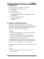
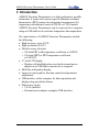
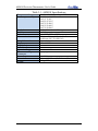
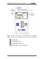
AM8010 Precision Thermometer User’s Guide AM8010 Precision Thermometer User’s Guide Table of Contents 1 Package List .......................................................................................... 2 2 Important Safety Information ................................................................. 2 3 Introduction ........................................................................................... 4 4 General Operations ............................................................................... 8 4.1 Mode switch setting.......................................................................... 8 4.2 Battery installation ........................................................................... 8 4.3 Power with external adapter and USB .............................................. 9 4.4 Sensor connection............................................................................. 9 4.5 Power on/off control ....................................................................... 10 4.6 Display of measurement results ...................................................... 10 4.7 TOUCHPAD operating .................................................................. 11 5 Connecting to a Computer Using USB Interface .................................. 12 5.1 Installation of USB driver to a computer ........................................ 12 5.2 Cool Edge USB Viewer Software ................................................... 16 6 Sensor Parameters Input/Adjustment ................................................... 18 7 Calibrations ......................................................................................... 24 7.1 Instrument Calibration .................................................................... 24 7.2 System Calibration ......................................................................... 26 8 Sensor Connector Assembly and Pin Configuration ............................. 30 9 Limited Warranty & Limitation of Liability ......................................... 32 1/33 AM8010 Precision Thermometer User’s Guide 1 Package List The following items are included in this package: One AM8010 Precision Thermometer One USB cable Two AAA Batteries One 5-pin sensor connector o Installed to the probe when purchasing together with an AccuMac PRT One CD with following software: o Cool Edge USB Viewer o USB driver 2 Important Safety Information AM8010 is designed to be a high accuracy temperature measurement and calibration instrument that can be used in labs and fields. Users should read and understand the following Warning to avoid electrical shoot and injuries. Warnings: Do NOT use the instrument in an environment with high moisture or damp conditions Do NOT use the instrument in applications other than specified as temperature measurement and calibrations Do NOT clean the instrument with solvents Do NOT apply voltage more than specified in this manual Do NOT place the instrument in a hot or cold environment Do NOT place any weight on top of the instrument Following Cautions should be followed to avoid damages of the instrument. Cautions: Only use this instrument in the manufacture specified temperature range. 2/33 AM8010 Precision Thermometer User’s Guide Do Not operate this instrument in a wet, dusty or dirty environment This instrument together with the probe it connects is sensitive to mechanical shocks. Do not drop or slam the instrument in anyway Only trained personnel can perform calibrations of this instrument 3/33 AM8010 Precision Thermometer User’s Guide 3 Introduction AM8010 Precision Thermometer is a high performance portable instrument. It works with various types of platinum resistance thermometer (PRT) sensors for temperature measurement. Its temperature calculation is based on ITS-90 or CVD formula. AM8010 Precision Thermometer can be connected to a computer using an USB cable to do real time temperature data acquisition. The main features of AM8010 Precision Thermometer include the following: High accuracy, up to 0.03ºC. High resolution (0.01ºC). Flexible sensor selection: o 100 ohm PRT with temperature coefficient α=0.00385. o 100 ohm SPRT or PRT temperature coefficient α=0.003925. 2.7 inch LCD display o Display with backlight when used with external power adapter or an USB cable connected to a computer. Multi line information display. Large size touch pad for function controls and parameter adjustments. USB interface with a computer for data acquisition and display using provided software. Dual power supply o 2 AAA batteries. o External power adaptor /computer USB interface. 4/33 AM8010 Precision Thermometer User’s Guide Table 3-1: AM8010 Specifications Temperature Range Accuracy (meter only) Resolution Stability Probe Characterizations Sample Interval Display Display Units Excitation Current Operation Range Thermometer Input Connectors Power Requirements Dimension Weight -200°C to 850°C, depending on PRT used ±0.04°C @ -200°C ±0.03°C @ 0°C ±0.04°C @ 232°C ±0.05°C @ 420°C ±0.06°C @ 660°C ±0.07°C @ 850°C 0.01°C (0.001 Ω) over full range ±0.01°C 100 Ω RTD, PRT or SPRT ITS-90 coefficients, Callender Van Dusen coefficients, IEC-751 (DIN 385) 1 second 2.7 inch OLED °C, °F, Ω 1 mA, reversing 15 °C to 35 °C 5-pin plug 100-240 V 141mm (L) X 25 mm (H) X 89 mm (W) 0.2 kg (0.5 lbs) 5/33 AM8010 Precision Thermometer User’s Guide Figure 3-1: AM8010 front panel. Figure 3-1 shows the front panel of AM8010 and its parameter display. There are four function keys that are defined as followings: MENU : MENU KEY, : INCREMENT KEY, : DECREMENT KEY, and : RIGHT SHIFT and RETURN KEY. 6/33 AM8010 Precision Thermometer User’s Guide The top panel of AM8010 is shown in Figure 3-2. There are three interfaces: “SENSOR”,“USB or EXT POWER” and power switch “OFF/ON”. Figure 3-2: AM8010 Top Panel. A foldable tilt foot support is mounted on the back of AM8010. It helps user to put the meter in a stable position with a display angle. There is a battery cover on the back side of AM8010 Precision Thermometer. Two AAA size batteries are used to power the meter. A sliding switch besides the battery holder can be seen when the battery cover is opened. This switch is used for calibration only. Warnings: Inappropriate setting change to this switch can cause loss of calibration data. Instructions of using this switch are shown in 4.1. 7/33 AM8010 Precision Thermometer User’s Guide 4 General Operations 4.1 Mode switch setting There are two operating modes of AM8010: Measurement Mode and Calibration Mode. Users can switch the mode by using a Mode Switch. The Mode Switch is located near the battery holder. The default mode is set to Measurement Mode. Note: Only trained calibration personnel can set the switch to “Calibration Mode”. See detailed instructions of calibration procedure in Chapter 7. The procedures to set this switch are as followings。 1. Turn off AM8010. 2. Open the battery cover at the back side of AM8010. Mode Switch, which is a sliding switch, is located besides the battery holder. 3. Text “MEA” and “ADJ” indicate whether AM8010 is set to “Measurement Mode” or “Calibration Mode”. 4.2 Battery installation AM8010 works with dual power supplies: battery and USB. When AM8010 is powered by USB, batteries are not used even there are batteries installed in the battery holder. To install the batteries, just open the battery cover at the back side of AM8010, follow the polarity signs on the battery holders. AM8010 works with any type of AAA size batteries, like alkaline or rechargeable batteries. Caution: Do NOT combine different kind of batteries together. Make sure the power switch is at “OFF” position when doing battery installation. 8/33 AM8010 Precision Thermometer User’s Guide 4.3 Power with external adapter and USB An AC/DC adapter (AC 100V ~ 240V input, DC5V output) can be used to power AM8010. The advantage of using the adapter is that the backlight of the LCD display will be turned on and it is suitable for dim light condition. The connection procedures of the AC/DC adapter are as follows: 1. Connect USB A side to the adapter USB socket. 2. Connect USB mini-B side to “USB” connector of AM8010. 3. Plug the adapter to AC 100V ~ 240V power point. Switch on the AC power 4. If AM8010 is not powered on, switch it on. If AM8010 is already powered by batteries and the power switch is on, the backlight of LCD should be on. 5. The USB cable can be unplugged at anytime. If AM8010 is powered by batteries, it should still work properly. AM8010 can be connected to a computer with USB interface. In this case the computer is the power source for AM8010. 4.4 Sensor connection PRT Sensors can be connected to the AM8010 “SENSOR” socket with a 5-pin connector that is provided in this package. Connecting steps are as followings: 1. Align the notch of sensor plug to the notch of “SENSOR” socket. 2. Push in the sensor plug. At this moment, do not turn the knob. A wrong turning of the sensor connector can cause damage of the socket and plug. 3. After the plug is fully pushed in, turn the knob of the plug clock-wise until it is fully tightened. 9/33 AM8010 Precision Thermometer User’s Guide 4. To remove the sensor, just do the reverse way of the above procedure: turn the plug knob counter clock-wise, until it is fully untouched, then pull out the plug. 4.5 Power on/off control The power switch is on the top penal of AM8010. It is marked with “OFF/ON” text. Users can follow the sign to turn on/off the meter. 4.6 Display of measurement results The temperature measurement results are displayed on the LCD screen. There are four lines of information as shown in Figure 3-1. The main information is temperature in Celsius (C), Fahrenheit (F) and sensor resistance (OHM). The other information includes sensor type, USB connection status, battery low status and no sensor indications. The first line is status information line. The second, third and fourth line shows the measured data, which are temperature or sensor resistance. As shown Figure 3-1, the top line is status information line. The information includes: 1. Status sign. It is a blinking dot at upper left corner. It should blink under normal conditions. 2. Main measurement parameter. It is located just at right side of the status sign. It should be either “t =” or “Rt =” which means the second line information is temperature (“t=”) or sensor resistance (“Rt=”). The information of the second line can be changed by users. The details are shown in “4.7 TOUCHPAD Operation”. 3. USB status. When AM8010 is connected to a computer’s USB interface,“USB” will show up near center of the first line. 10/33 AM8010 Precision Thermometer User’s Guide 4. Sensor type. Two types of sensor, “IPRT” or “PRT”, are supported by AM8010. There are displayed as “IPRT” or “PRT” on the LCD near the end of the first line. Users can configure the sensor type by following the procedures that are detailed in Chapter 6 “Sensor Parameter Input/Adjustment”. “IPRT” is defined as a 100 Ω sensor with temperature coefficient α=0.00385. “PRT” is defined as a 100 Ω SPRT/PRT with temperature coefficient α=0.003925 (WGa≥1.11807). 5. “NO SENSOR” status. “NO SENSOR” will be displayed when no sensor is connected to AM8010. 6. “LOW BAT” status. “LOW BAT” is displayed when the batteries are low in power. The second line shows the measured results with larger fonts to help users to focus on the key readings. The information of second, third and fourth line can be scrolled up or down based on user’s preference. 4.7 TOUCHPAD operating There are four touch keys on AM8010 front panel. These touch keys are used for scrolling up/down measurement data, or for sensor parameter adjustment and calibrations. Note: These keys are not mechanical push button. They are only sensitive to finger touch. When the meter is set to Measurement Mode and are for user to choose scroll up/down the measured readings in Celsius (C), Fahrenheit (F) and sensor resistance (OHM). MENU and keys can be used for sensor type selection and sensor parameter adjustment. These two keys are also used in Calibration Mode (see Chapter 6). 11/33 AM8010 Precision Thermometer User’s Guide 5 Connecting to a Computer Using USB Interface AM8010 is designed with an USB v2.0 compatible interface (Mini B type) and it can be connected to a PC. The USB interface serves two important functions as a power source (see Chapter 4.3) and a link of data acquisition. A free software Cool Edge Viewer is provide with AM8010 for real time data acquisition. 5.1 Installation of USB driver to a computer Important Update: if your PC is running Windows7 (or later versions) operating system, you can skip USB driver installation process. These versions of windows OS provide plug-and-play support for USB drivers. Otherwise, please follow the instructions below. a) Power off AM8010. b) Connect a USB cable (one side USB A type, another side mini-B type) to a USB socket on a computer. c) Power on computer and put the attached CD into a CD drive. Here assume the CD drive is E. d) Connect USB mini-B side to AM8010. Switch on AM8010, AM8010 LCD display should show “USB” on the first line. The computer also should show “Found New Hardware”. 12/33 AM8010 Precision Thermometer User’s Guide e) Select “No, not this time” , then mouse right click on “Next”, f) Select “Install from a list or specific location (Advanced)” and then mouse right click on “Next”, 13/33 AM8010 Precision Thermometer User’s Guide g) Use “Browse” to find the driver in E. refer to the above figure,then mouse right click to select “Next”, h) Select “Continue Anyway”, the computer may request for another file “FTD2XX.sys”. 14/33 AM8010 Precision Thermometer User’s Guide i) Use “Browse” to search E drive to find and select FTD2XX.sys , mouse right click on “OK”. After the installation, the computer should show: j) Select “Finish” to end the installation. k) The computer should show “Your new hardware is ready to use” to indicate that the installation is finished. 15/33 AM8010 Precision Thermometer User’s Guide 5.2 Cool Edge USB Viewer Software “Cool Edge USB Viewer” enables AM8010 to communicate with a computer USB interface and display the measurement results on computer monitor. It also enables users to save the captured data to a file on computer. Details of setting up the data acquisition system using the software are as followings: a) Turn on computer and copy the software “Cool Edge USB Viewer” from the CD provided to computer desktop. b) Connect a USB cable between computer and AM8010. c) Turn on AM8010, after a few seconds, the first line of AM8010 LCD display will show “USB”. d) Double click the icon of “Cool Edge USB Viewer” on computer desktop to start the software. e) Cool Edge USB Viewer should start and show followings: 16/33 AM8010 Precision Thermometer User’s Guide f) Click on the “Start” button, the software should show the measurement data as followings: g) Users can use the “Data Saving” function at the right side to save the data if needed. The first step is to set the sampling rate. The above Figure shows the “Data Saving” and the default sampling rate is 1 sec. if other sampling rate is needed, users can key in other integer number between 1 to 65535 seconds. Users can start to record data by click on “REC” button. To end the data recording, just click on “END” button to stop. The captured data are saved to a file with name of“cool_data.txt”. h) To stop data measurement, click on “Stop”。 i) To quit the software, click on “Exit”。 17/33 AM8010 Precision Thermometer User’s Guide 6 Sensor Parameters Input/Adjustment AM8010 supports two types of sensors: IPRT and PRT。 IPPT:high precision 100 ohm Platinum Resistance Thermometer or Industrial 100 ohm Platinum Resistance Thermometer with temperature coefficient of α=0.00385. The temperature is calculated based on CVD formula. User can input/adjust following parameters of an IPRT: R0, A, B and C. PRT:high precision 100 ohm Platinum Resistance Thermometer or 100 ohm standard Platinum Resistance Thermometer (SPRT) with temperature coefficient of α=0.003925 (WGa≥1.11807). The temperature is calculated based ITS-90 formula. User can input/adjust the following parameters: Rtp:the sensor’s triple points of water. a4, b4:low temperature range parameters. a, b, c:high temperature range parameters ( for some type of sensors, b and c may equal to 0. Refer to ITS-90 for details). After users input/adjust the correct parameters the sensor type is displayed on the LCD of AM8010 and the parameters are used in the calculation. Note: Users need to set the parameters corresponding to the sensor to get the optimal measurement. These parameters can be obtained from qualified calibration institutes. The detailed procedure to set the sensor type and parameters are as followings: 1. Power off AM8010. Install batteries to AM8010, or connect AM8010 to a power adapter or a running computer USB interface. Make sure each battery is with enough power. It is suggested to use new batteries for parameter setting or calibration. 18/33 AM8010 Precision Thermometer User’s Guide 2. Set the Mode Switch to Measurement Mode. Refer to 4.1Mode switch setting. 3. Power on AM8010. If a sensor is connected to AM8010,the LCD should display the measurement reading. See the flowing figure as an example. If no sensor is connected users can still set parameters of a sensor. 4. Press and hold key for more than 3 seconds,the right down corner of LCD should show “MENU”. MENU IPRT t= C 27.0956 Rt = 110.6500 t = 80.772 OHM F MENU MENU Then hold the key and press the key with another finger. AM8010 should enter into adjustment program. 5. Followings will be displayed on LCD after step 4. If no adjustment or setting is needed, press or the highlight line to “ EXIT” and then press AM8010 will go back to measurement mode. key to move key , * MAIN MENU SENSOR SETTING EXIT Enter = Yes 6. Move the highlight line to “SENSOR SETTING” and press key to adjust sensor’s settings. displayed: Followings will be 19/33 AM8010 Precision Thermometer User’s Guide SENSOR = IPRT IPRT PRT Menu = Exit Enter = Yes 7. As illustrated in the above Figure, the first line shows the current sensor type. If the connected sensor type is different from the current setting (IPRT for example), the sensor type needs to be changed. Moving the highlight line to the correct line by press or , and then press key to select. The program will move into parameter adjustment section as illustrated in step 8. 8. For example,if IPRT is selected,the LCD displays the followings : IPRT SETTING SET R0 SET A SET B User can adjust R0, A, B and C in this section. Press key to select and press key to go back to previous screen when adjustments are done. MENU 9. If PRT is selected ,the LCD display the followings: PRT SETTING SET Rtp SET a SET b 20/33 AM8010 Precision Thermometer User’s Guide User can adjust Rtp, A4, B4, A, B and C in this section. Press MENU key to select and press key to go back to previous screen when adjustments are done. 10. Followings are examples of setting R0 and A4 values. The adjustment of the other parameters can be done in similar way. I. R0 adjustment: i. Continue from 6.1.8,press will show: R0 key and the LCD OHM 100.0100 Menu = Save Enter = Shift ii. The value of second line shows the current R0 value. The cursor shows the adjust position. To modify the value, press or to tune the value up or down. Pressing will shift the cursor to next position. After the last digit is finished, pressing again will move the cursor go the most left position. There is no left shift key. iii. After R0 is adjusted,press key and the LCD should show: MENU SAVE R0 100.0000 Menu = No Enter = Yes iv. The second line should blink to remind user to save the new value. If users do not want to save 21/33 AM8010 Precision Thermometer User’s Guide this value, press MENU to quit the adjustment; if users want to save this new value, press . The new R0 value will be saved into the meter. The program will go back to 6.1.8. II. To adjust a4 value, continue from 6.1.9. i. Move the highlight line by pressing key multiple times until “SET a4” is highlightened. Press to select, the LCD should show: a4= - 4.129934e-05 SET a4 =0 ADJUST a4 Menu = Exit Enter = Yes ii. The first line is the current a4 value. The second line should be selected if a4=0. The third line allows the user to adjust the a4 value. Press or to move the highlight line. If a4 needs to be adjusted, move the high light line to “ADJUST a4” then press . The LCD should show: SET a4 - 4.129934 e - 05 Menu = Save Enter = Shift iii. The blinking cursor shows the adjustable digit. Pressing or change the value up or down. Pressing pad will move the cursor to the right position. If the cursor is at the most right position, 22/33 AM8010 Precision Thermometer User’s Guide press key again will move the cursor to the most left position. After the a4 adjustment is done, press MENU and the LCD should show: SAVE a4 - 4.129934 e - 05 Menu = Exit Enter = Yes iv. The first line display “SAVE” to remind user that the meter is preparing to save the new a4 value, the blinking second line is to remind user to make a decision. MENU v. Press to exit without saving. Press the new a4 value to AM8010. to save The other parameters can be adjusted in the similar ways as the above. 23/33 AM8010 Precision Thermometer User’s Guide 7 Calibrations AM8010 is designed for temperature measurement by measuring the probe resistance and converting it into a temperature. Consequently, the resistance measurement is very critical, and the instrument must be calibrated correctly. Every AM8010 is calibrated before shipment. AM8010 needs regular calibration performed by qualified professionals. One year calibration interval is recommended. Users can calibrate AM8010 using standard resistors with calibrated values. Users can choose to do one of the two calibrations:Instrument Calibration and System Calibration. 7.1 Instrument Calibration Instrument Calibration is to calibrate measurement accuracy of AM8010. the resistance Note: a standard resistor with resistance of 100 ohm is required for the Instrument Calibration. Set AM8010 to Calibration Mode before start the calibration (See Chapter 4.1). Calibration steps are as followings: 1. Connect a 100 ohm standard resistor with four-wire configuration to AM8010. In the illustrations below a standard resistor with 100.0038 ohm resistance is used as an example. It is suggested to use external power adapter or to connect the AM8010 to a USB interface on a running computer during calibration. If battery power is used make sure the batteries are not running low. Power on AM8010, and the LCD should display: 24/33 AM8010 Precision Thermometer User’s Guide * CALIB MENU CALIBRATION Enter = Yes 2. Press key,the display will show : Rs = OHM 99.9999 Rt = 99.9888 OHM 3. The second line shows the internal reference Rs value (value may be different from meter to meter). The third line shows the current external standard resistor resistance reading Rt = 99.9888 ohm, which is not equal to the real external standard resistor value 100.0038 ohm. The following Instrument Calibration procedures are to adjust the Rs value to make Rs value equal to 100.0038 ohm and save the new Rs to the instrument: 4. Press or key to adjust the Rs value at the cursor position. Press key to right shift the cursor for a new position during the adjustments. 5. After the adjustment, the second line value should be 100.0038 ohm. Rs = OHM 100.0038 Rt = 100.0038 OHM 6. Wait for Rt and Rs to be stable ( the status sign should blink around 10times),then press pad,the LCD should MENU 25/33 AM8010 Precision Thermometer User’s Guide display: SAVE Rs 100.0038 Menu = No Enter = Yes And the second line should be blinking. Press key to save the new Rs. Press the key to exit without saving. MENU After the calibration, turn off power of AM8010 and change back the Mode Switch to Measurement Mode. 7.2 System Calibration System Calibration is based on the Instrument Calibration. It is to integrate a particular PRT sensor with AM8010 after Instrument Calibration to form a temperature measurement system. This system is to be calibrated at certain temperature points to calculate sensor’s coefficients based on AM8010’s readings. These coefficients are then saved in AM8010 after calibration to achieve better measurement performance as a system. The advantage of System Calibration is that it can achieve higher accuracy with lower cost because the sensor doesn’t need additional calibrations before System Calibration. The following sections illustrate System Calibration procedure with two types of sensors “IPRT” and “PRT”. 7.2.1 Calibration with IPRT (high precision 100 ohm or industrial 100 ohm Platinum Resistance Thermometer with α=0.00385) 26/33 AM8010 Precision Thermometer User’s Guide 1. Turn off power of AM8010, make sure it is at Measurement Mode (see Chapter 4.1 for details). 2. Connect the sensor to AM8010. Power on AM8010, and put the sensor into temperature bath or fix point cells. 3. High temperature range calibration: three temperature points are needed which are ice point (triple points of water), temperature close to upper limit, and a point in between. Note down the measurement results at all these three points. For example , the following three temperature points from 0ºC to 300ºC are selected and after the calibration, the following group of data are acquired. Standard temperature t 0ºC 150ºC 300ºC AM8010 measured R(t) resistance value R(0ºC) R(150ºC) R(300ºC) Apply the above data to :R(t)=R(0ºC)*(1+At+Bt2) then parameters A and B can be calculated. 4. Low temperature range calibration : Measure another temperature point that is close to the probe’s lower temperature limit using AM8010. For example, the following data is acquired: Standard AM8010 measured R(t) temperature t resistance value -60ºC R(-60ºC) Apply the calculated A and B,together with the new low temperature data to: 27/33 AM8010 Precision Thermometer User’s Guide R(t)=R(0ºC)*[1+At+Bt2+C(t-100)t3] Then C value can be calculated. 5. Key in the A,B,C and R0 to AM8010. The system calibration is done. Turn off the power after calibration. 7.2.2 Calibration of PRT (high precision 100 ohm or standard 100 ohm Platinum Resistance Thermometer with temperature coefficient α=0.003925(WGa>1.11807) 1. Turn off power of AM8010, set it to Measurement Mode. (See Chapter 4.1 2. Connect the sensor to AM8010. Power on AM8010, and put the sensor into temperature bath or fixed point cell. 3. Choose more than three temperature points to measure based on the sensor’s temperature range and ITS-90 standard. 4. These measurement data can be applied to the calculation of sensor’s temperature coefficients based on ITS-90 formula. For example, the following data are acquired between 0ºC to 300ºC. Standard temperature t 0.01ºC 150ºC 300ºC AM8010 measured R(t) resistance value R(0.01ºC) R(150ºC) R(300ºC) 28/33 AM8010 Precision Thermometer User’s Guide Apply the above data to ITS-90 formula: W-Wr=a(W-1)+b(W-1) 2 - c(W-1) 3 where,W=R(t)/R(0.01), and C0, Ci are constant values,T90 = t +273.15,R(0.01) is the sensor’s triple points of water, and R(0.01) is named as Rtp in AM8010. The details can be found in ITS-90 standard. The sensor’s parameters a, b and c can be calculated based on the above data and formula. 5. Key in the a, b, c and Rtp into AM8010. After the parameters are saved, the system calibration is done. More details about the coefficients and temperature calculations can be found in ITS-90 standard. Turn off the power after calibration. 29/33 AM8010 Precision Thermometer User’s Guide 8 Sensor Connector Assembly and Pin Configuration The sensor connector is a 5-pin round connector with retention relief. The assembly drawing is shown in the following figure. Figure 8-1: sensor connector assembly drawing. The pin configuration of the connector is shown as in Figure 8-2. 3 4 2 1 5 Figure 8-2: Rear view of the 5-pin connector. There are 5 pins on the connector. For a 4-wire platinum sensor, pin1 and pin2 should be one end of the sensor, and pin4 and pin5 should be another end of the sensor. Pin3 cab be optionally connected to cable shield or left open. One example of pin configuration is shown in the following Error! Reference source not found.. Table 8-1: pin configuration of 4-wire platinum sensor. Pin Number Wire color 1 Red 2 Black 3 Shield, or open 4 White 5 Green After assembly with PRT sensors, the resistance between red and black, or white and green, should be < 2 ohm. The 30/33 AM8010 Precision Thermometer User’s Guide resistance between black/red and white/green should be around 110 ohm (for 100 ohm PRT). 31/33 AM8010 Precision Thermometer User’s Guide 9 Limited Warranty & Limitation of Liability The material contained in this document is provided “as is,” and is subject to being changed, without notice, in future editions. AccuMac shall not be liable for errors or for incidental or consequential damages in connection with the furnishing, use, or performance of this document or of any information contained herein. Should AccuMac and the user have a separate written agreement with warranty terms covering the material in this document that conflict with these terms, the warranty terms in the separate agreement shall control. Each product from AccuMac Corporation is warranted to be free from defects in material and workmanship under normal use and service. The warranty period is 1 year AM8010 Precision Thermometer. The warranty period begins on the date of the shipment. Parts, product repairs, and services are warranted for 90 days. The warranty extends only to the original buyer or end-user customer of an AccuMac authorized reseller. The warranty will not extended to products that have been misused, altered, neglected, or damaged by accident or abnormal conditions of operation or handling. To obtain warranty service, contact AccuMac Corporation at: 3150 N Arizona Ave STE 103 Chandler, AZ 85225 USA Tel: (480)634-0603 Email: [email protected] 32/33