1
INSTALLATION
4.2
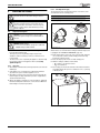
Wall mounting plate and flue opening
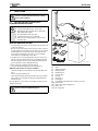
CAUTION: Ensure there are no pipes, electric cables,
damp proof courses or other hazards before drilling.
SAFETY:
All relevant safety precautions must be undertaken. Protective clothing,
foot wear, gloves and safety goggles must be worn as appropriate.
FIXING THE POSITION OF THE WALL MOUNTING PLATE:
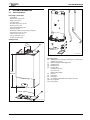
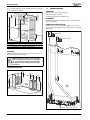
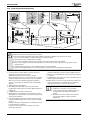
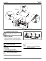
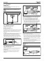
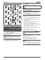
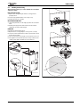
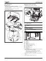
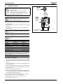
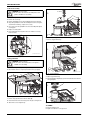
• Fig. 25 shows the relative positions of the flue and the fixing of the
wall mounting plate including hanging bracket and pre-plumbing
manifold.
min. 22
4.
FLUE OUTLET
▶ Follow the Fig. 25 to mark the centre of the flue for rear outlet (3) or
for side outlet (4).
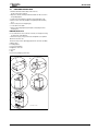
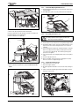
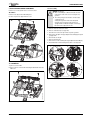
▶ For the 60/100mm Ø flue make a 125 mm diameter hole through
the wall using a core drill or similar.
For flues using an optional weather collar, fitted from inside the
building make a 150 mm Ø hole.
▶ Clear away any debris.
▶ Drill the hole, preferably using a core drill.
▶ Remove the mounting template.
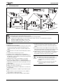
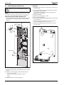
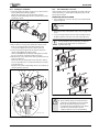
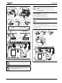
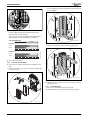
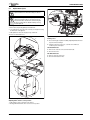
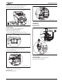
▶ Place the wall mounting plate with hanging bracket against the wall in
the desired position.
▶ Secure wall mounting plate with four screws (supplied with the
boiler). Do not fully fasten the lower two screws.
▶ Mount the pre-plumbing manifold on the two lower screws and
secure the screws.
5 mm
3.
1.
holes B
85 mm
2.
hole B
Hanging
bracket
2.
holes A
hole A
min. 5 mm
2.
hole C
hole C
hole D
2.
hole D
6 720 812 174-21.1O
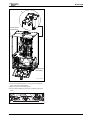
Fig. 26 Wall mounting plate and pre-plumbing manifold
6 720 812 175-27.1O
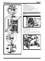
Fig. 25 Mounting template
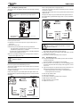
▶ Fix the wall mounting template, supplied with the literature pack, to
the wall.
▶ Drill holes for wall mounting plate and pre-plumbing manifold:
– at least one of the holes A,
– at least one of the holes B (preferably use left hole),
– hole C,
– hole D.
▶ If required: make a hole in wall for the flue pipe.
20
6 720 815 723 (2015/05)