1
SERVICING AND SPARES
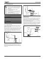
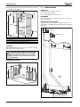
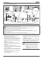
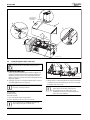
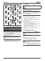
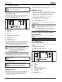
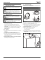
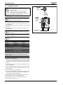
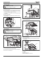
13. Electrode assembly
WARNING: Electrode gasket
▶ Do not remove the electrode assembly unless a new
gasket is available for re-assembly.
F
2.
C
▶
▶
▶
▶
Disconnect spark electrodes and flame sensor connection.
Remove two screws (F).
Remove spark/flame electrode assembly (G) from heat exchanger.
Inspect the spark/flame electrode assembly and ceramics for signs of
contamination or damage, replace as necessary.
▶ If necessary, clean the spark/flame electrode assembly with a plastic
scouring pad.
▶ Replace electrode gasket.
▶ Re-assemble with the new gasket and secure with the screws (F)
removed earlier.
D
6 720 812 175-16.1O
13
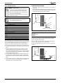
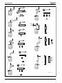
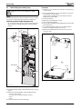
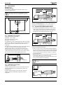
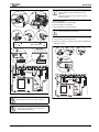
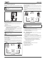
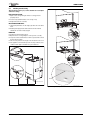
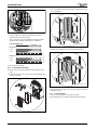
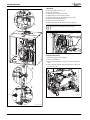
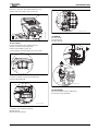
Fig. 79 Release air/gas manifold
3. Remove air/gas manifold (I)
G
E
G
3.
F
6 720 812 175-20.1O
Fig. 77 Electrode assembly
H
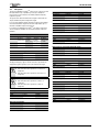
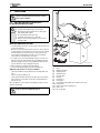
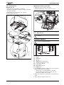
14. Air/gas manifold
WARNING: Air/Gas manifold
▶ Do not remove the manifold unless a new gasket is
available for re-assembly.
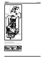
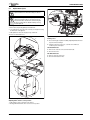
1. Remove cover panel (A) by removing screws (B).
▶ Check that the boiler is completely isolated from the gas supply.
6 720 812 175-17.1O
1.
B
A
B
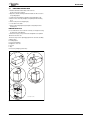
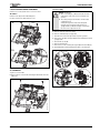
Fig. 80 Air/gas manifold
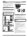
4. Open air/gas manifold (I).
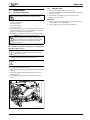
▶ Carefully withdraw diaphragm (J) from fan intake tube and check for
soiling and splits.
4.
J
K
Fig. 78 Top panel
I
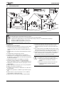
2. Remove clips (C) and unscrew the two bolts (D).
▶ Unscrew and remove the two hexagon screws (E) securing the fan.
▶ Slacken the rear securing bolt (F).
6720647361-66.1Wo
6 720 812 175-15.1O
Fig. 81 Diaphragm
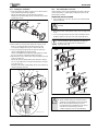
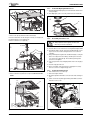
15. BURNER
▶ Remove the burner (H).
▶ Replace new burner in correct position.
42
6 720 815 723 (2015/05)