1
Contents
STANDARD OPERATING PROCEDURES FOR SCREENING, RECRUITMENT OF
PREGNANT MOTHERS AND COLLECTION OF MATERNAL HEALTH, BIRTH
OUTCOME AND CHILD HEALTH (ARI) DATA ..................................................................... 6
1. Purpose and scope ................................................................................................................. 7
2. Summary of the method ....................................................................................................... 7
3. Tool Box Meetings .................................................................................................................. 8
4. Screening for eligibility at primary health care centres (PHC) /urban
health posts(UHP) ( Data Form MC 1) ................................................................................. 8
5. Obtaining informed consent from eligible mothers at the household ( Data
Form MC 2)................................................................................................................................. 11
6. Collection of maternal (antenatal) health data ( Data Form MC 3) ................... 12
7. Collection of Birth Outcome Data (Data form MC 4) ............................................... 17
8. Collection of ARI Data ( Data Form MC 5) ................................................................... 19
9. Data quality and data management .............................................................................. 32
10. References........................................................................................................................... 34
STANDARD OPERATING PROCEDURES FOR ASSESSING CHRONIC
RESPIRATORY SYMPTOMS AND ASSESSMENT OF LUNG FUNCTION IN ADULT
MEN AND WOMEN.................................................................................................................... 35
1. Purpose and scope .............................................................................................................. 36
2. Summary of the method .................................................................................................... 36
3. Tool Box Meetings ............................................................................................................... 37
4. Screening for eligibility at the household (Data Form AC 1) ............................... 37
5. Obtaining informed consent from eligible participants at the household
(Data Form AC 2). .................................................................................................................... 40
6. Collection of data on chronic respiratory symptoms (Data Form ACINSEARCH 3) .............................................................................................................................. 41
7. Assessing pulmonary function by spirometry (Data Form AC 4) ...................... 48
8. Data quality and data management.............................................................................. 61
1
STANDARD OPERATING PROCEDURE FOR SAMPLING AND ANALYSIS OF
PARTICULATE MATTER IN HOUSEHOLD MICRO-ENVIRONMENTS ........................ 63
1. Purpose ................................................................................................................................... 64
2. Scope and Applicability..................................................................................................... 64
3. Summary of procedures ................................................................................................... 64
4. Tool-box meeting ................................................................................................................ 65
5. Laboratory activities.......................................................................................................... 65
6. Field activities ...................................................................................................................... 77
6.4 Administration of the General Household and Post Monitoring
Questionnaire (Data Form EXP 7) ..................................................................................... 81
6.5 Post Monitoring Questionnaire .................................................................................. 90
7. Calculation of PM Concentrations/Exposures .......................................................... 95
8. References ............................................................................................................................. 97
STANDARD OPERATING PROCEDURE (SOP) FOR SAMPLING AND
DETERMINATION OF PM10 AND PM2.5IN AMBIENT AIR USING HIGH VOLUME
SAMPLER..................................................................................................................................... 98
1. Purpose ................................................................................................................................... 99
2. Scope and Applicability..................................................................................................... 99
3. Apparatus description....................................................................................................... 99
4. Apparatus set-up ...............................................................................................................100
5. Calibration ........................................................................................................................... 103
6. Sampling procedure .........................................................................................................104
7. Field QC procedure ...........................................................................................................105
8. Calculations ......................................................................................................................... 106
STANDARD OPERATING PROCEDURE FOR SAMPLING AND ANALYSIS OF
VOLATILE ORGANIC COMPOUNDS (VOCs) IN HOUSEHOLD MICROENVIRONMENTS .....................................................................................................................108
1. Purpose .................................................................................................................................109
2
2. Scope and Applicability...................................................................................................109
3. Summary of Method .........................................................................................................109
4.Tool-box meeting ...............................................................................................................110
5. Laboratory activities........................................................................................................110
6. Sorbent tube conditioning and preparation ........................................................... 111
7. Air sampler calibration ...................................................................................................112
8. Field Activities....................................................................................................................112
9. Analysis of VOCs ...............................................................................................................114
10. Reference....................................................................................................................... 1143
STANDARD OPERATING PROCEDURE FOR SAMPLING AND ANALYSIS OF
GASEOUS CONTAMINANTS (NOx-NO2, SO2 and O3) IN HOUSEHOLD AND
AMBIENT ENVIRONMENTS .................................................................................................116
1.Purpose..................................................................................................................................117
2. Scope and Applicability...................................................................................................117
3. Summary of Methods .......................................................................................................117
4. Equipment and supplies .................................................................................................118
6. Sampling ............................................................................................................................... 122
7. Disassembly of the sampler .......................................................................................... 123
8. Cleaning ................................................................................Error! Bookmark not defined.
9. Reference............................................................................ Error! Bookmark not defined.4
STANDARD OPERATING PROCEDURE FOR SAMPLING AND ANALYSIS OF
TRACE METALS IN HOUSEHOLD MICRO-ENVIRONMENTS ......................................127
1. Purpose .................................................................................................................................128
2. Scope and Applicability...................................................................................................128
3. Summary of Method .........................................................................................................128
4. Materials required............................................................................................................129
3
4.4 Calculation ........................................................................................................................ 136
4.5 Quality Control ................................................................................................................136
STANDARD OPERATING PROCEDURE FOR SAMPLING AND ANALYSIS OF
POLYCYCLIC AROMATIC HYDROCARBONS (PAHs) IN HOUSEHOLD MICROENVIRONMENTS .....................................................................................................................138
1. Purpose .................................................................................................................................139
2. Scope and Applicability...................................................................................................139
3. Summary of method .........................................................................................................139
4. Tool-box meeting ..............................................................................................................140
5. Laboratory activities........................................................................................................140
6. Sampling procedure and storage..……………………………………………………………142
7. Sample extraction..………………………………………………………………………………….143
8. Analysis of PAHs.……………………………………………………………………………………..144
9. Calculation and reporting.……………………………………………………………….………149
10. Safety……………………………………………………………………………………………….……151
11. Quality assurance and quality control…………………………………………………..152
12. References………………………………………………………………..…………………………..153
STANDARD OPERATING PROCEDURE FOR LAND USE REGRESSION
ALGORITHMS........................................................................................................................... 157
STANDARD OPERATING PROCEDURE FOR BIOREPOSITORY: SAMPLE
ARCHIVAL AND ANALYTICAL PROTOCOL .....................................................................160
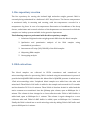
1. Bio-repository creation ..................................................................................................161
2. DNA extraction: ..................................................................................................................161
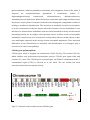
3. Single Nucleotide Polymorphism analysis: .............................................................. 162
4. Analysis of PCR amplicons ............................................................................................. 164
4
5
STANDARD OPERATING PROCEDURES FOR SCREENING,
RECRUITMENT OF PREGNANT MOTHERS AND COLLECTION
OF MATERNAL HEALTH, BIRTH OUTCOME AND CHILD
HEALTH (ARI) DATA
TAPHE-BW-ARI STUDY
ICMR-CAR PROJECT
DEPARTMENT OF ENVIRONMENTAL HEALTH ENGINEERING
ICMR CENTER FOR ADVANCED RESEARCH ON
ENVIRONMENTAL HEALTH: AIR POLLUTION
SRI RAMACHANDRA UNIVERSITY
CHENNAI, TAMIL NADU
SOP ID: 2.1- TAPHE-BW-ARI
Date of issue: 15 April 2010
Date of last review: 19 November 2014
Prepared by:
Reviewed by:
Mrs. Rajarajeswari
Kuppuswamy
Dr. Gurusamy Thangavel
Mrs. Uma Maheswari
Dr. Padmavathi Ramaswamy
Approved by:
Dr. Kalpana Balakrishnan
6
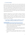
1. Purpose and scope
This document provides instructions to research personnel involved in the ICMR-CAR
project for collecting health data pertinent to the Tamil Nadu Air Pollution and Health
Effects-Birth weight-Acute respiratory infections (TAPHE-BW-ARI) Study. It includes
details for (i) screening pregnant women at primary health care centers (PHC) or urban
health posts (UHP) to assess eligibility for enrollment in the mother –child cohort (ii)
seeking informed consent to enroll both the mother and the child (iii) collecting
maternal (antenatal) health data (iv) collecting birth outcome data and (v) collecting
data on acute respiratory infections (ARI) in children less than 2 years old.
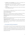
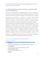
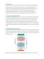
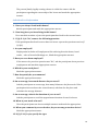
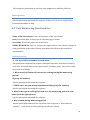
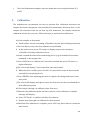
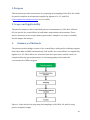
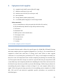
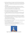
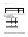
2. Summary of the method
The SOP covers five sequential steps (Figure 1) that includes (i) assigning field tasks for
health teams at tool-box meetings (using the Tool Box Information Sheet) (ii) screening
pregnant women presenting themselves at the respective PHCs/UHPs (using data form
MC-1) (iii) assessment of eligibility (iv) securing written informed consent (using data
form MC-2) (v) collection of maternal health data through household visits to cover
every trimester (using data form MC-3) (vi) collection of birth outcome data after
delivery of the child (using Data form MC-4) and (vii) collecting data on ARI in children,
through monthly household visits until 24 months of age (using Data form MC-5).
Figure 1: Steps involved in collection of health data in the TAPHE-BW-ARI Study
7
3. Tool Box Meetings
A 10-15min tool-box meeting is conducted every week to plan field activities and
logistics by the scientist in charge. Tasks are spread across the data collection elements
based on weekly, monthly or yearly targets for data collection and availability of field
teams/ vehicles. Check against the Tool Box Meeting Information Sheet (use Data Form
TB) for your assigned task before assembling relevant field materials. Take only
required number of copies of questionnaires or data forms. Document the date, location
of field visit, type and quantity of field equipment in the tool-box meeting data sheet,
every day (see Data Form TB). Do not assume a default schedule as the field schedules
change frequently and at short notice.
PHC/UHP have designated days of the week assigned for antenatal screening. The
schedule for recruitment teams should be based on the schedules of relevant
PHCs/UHPs. Prepare a call list based on intended area of visit to inquire about
availability of participant via phone. Include additional households in each list to
accommodate schedule changes. Organize data collection steps based on participant
availability as well as vehicle logistics.
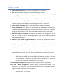
4. Screening for eligibility at primary health care centres
(PHC) /urban health posts(UHP) ( Data Form MC 1)
4.1 Steps at PHC/UHP
a. Introduce yourself to the PHC / UHP / staff and request them to direct
pregnant women presenting themselves at the antenatal clinic (preferably
less than 14 weeks of gestation) to the SRU recruiting team.
b. Introduce yourself (in Tamil) to the woman.
c. Brief her about the project (provide her with the CAR Information Sheet for
Participants) and ask if she would be interested in enrolling herself as a
study participant, if found eligible
d. Once she provides the initial (oral) informed consent to be screened,
administer the screening questionnaire (Data Form MC 1) as described
below
8
4.2 General instructions for administering screening questionnaire (Data
Form MC 1) at PHC
1. Name of the interviewer: Enter the full name of the interviewer.
2. Date: Record the date of interview in <dd/mm/yyyy> format.
3. Recruiting Location: Fill details regarding the location of the PHC/UHP
including village/zone name.
4. OP (outpatient) Number: Write down the PICME number as OP number for the
respondent at the PHC/UHP (Note for the few participants screened at other
hospital facilities, use available record locators such as scan # or id #)
5. Name of the participant: Write down the full name of the respondent
6. Name of husband: Write down the full name of the respondent’s husband (this
is additional identifying information would be useful for locating the household
during the first field visit, if the household address information is inaccurate)
7. Where do you live currently? Write down the name of the village/area. Do not
label it as urban or rural. This assignment is done at the laboratory while
assigning the unique ID.
8. Where do you intend to go for delivery? – Provide the respondent with the
enlisted options and encircle her response
9. Specify the locality of the place of delivery mentioned above: Write down
the name of village or area that the respondent intends to go for the delivery of
the child
10. Is that place within the study zone: Check against the villages and zones
included within our study area (MC Data Form 1a). Encircle either ‘Yes’ or ‘No’.
a. If the response is NO, she is not eligible for inclusion. Explain to her that
she is ineligible as the team will find it difficult to follow her during the
course of the pregnancy and thank her for her time.
11. Participant’s occupation: Write down the occupation of the respondent
12. Is that a dusty occupation? Common dusty occupations are listed in the
Annexure / MC Data Form 1a. If in doubt confirm from the respondent if she is
exposed to dust frequently in her workplace.
a. Encircle either ‘Yes’ or ‘No’.
9
b. If the response is Yes, she is not eligible for inclusion. Explain to her that
she is ineligible as the team will find it difficult to follow her at her
workplace to profile dust exposures (this being an air pollution related
health study) and thank her for her time.
13. Is this pregnancy conceived naturally? Ask the respondent, if the current
pregnancy was conceived naturally. In case she is not sure prompt her with
examples of common assisted reproduction methods, such as intrauterine
insemination (IUI), in-vitro fertilization (IVF).
a. If the response is Yes, she is not eligible for inclusion. Explain to her that
she is ineligible as the team will find it difficult to follow her during the
course of her pregnancy and thank her for her time.
14. Write down her last menstrual period from the hospital records in
<dd/mm/yyyy> format.
15. Write down her expected delivery date from the hospital records in
<dd/mm/yyyy> format.
16. Write down her current residence and her parent’s residence addresses
completely with pin code and contact mobile numbers.
If she is eligible based on responses to question 10, 12 and 13, ask her if she is
interested in being a study participant and sign an informed consent. If she is eligible
and willing to participate, encircle the option ‘INCLUDE’; if not eligible encircle
‘EXCLUDE’ and if eligible but not willing encircle ‘NOT WILLING’. If she is not willing,
request her to provide a reason and encircle the appropriate answer from the list
provided in the questionnaire.
Once a willing and eligible woman is identified, let her know that the research team
will come to her household with relevant forms for informed consent.
10
5. Obtaining informed consent from eligible mothers at the
household ( Data Form MC 2).
5.1 Steps for securing informed consent
1. Provide a consent form (MC Data Form 2) to the participant and request her to
get her doubts clarified (if any), once she reads it.
2. If she cannot read, read it for her and make her understand the content of the
consent form in the presence of another household member, who can read Tamil.
3. Get the signature of the participant with full name and date, after the participant
has understood her role in the study and voluntarily consents to be a participant
in the study.
4. Obtain a witness signature from the participant’s relative or another data
enumerator with full name and date.
5. Complete the interviewer’s statement and sign it with name and date.
6. Give the participant a copy of the signed consent form.
5.2 Assigning a participant ID
All enrolled participants are assigned with a TAPHE unique identifying number to link
all data fields pertaining to the participant and /or household. The assignment of unique
ID is done in the laboratory after securing the informed consent.
Unique ID: This is assigned at the lab. This is a 10 character alpha numeric code which is
assigned by combining three different entities. They are; 1) the type of cohort, 2)
location of cohort and 3) serial number of the cohort participant enrolled in a particular
village/city.
The first character is a text which is either M or A denote the type of cohort – ‘M’ for
mother –child and ‘A’ for adult cohorts. The next 8 digits represent the location of the
cohort; of which the first two characters are texts, which denote either ‘R’ for rural and
‘U’ for urban and ‘K’ for Kancheepuram district or ‘T’ for Thiruvellore district or ‘C’ for
Chennai district. The next six digits of the location component are written in Arabic
numeral which identify the village / zone and the household. The last digit of the unique
11
ID represents the serial number of the participant of that particular location. For e.g.
M/R/K/001/001/1 means it is a mother- child cohort from the rural area of
Kancheepuram district with a village ID 001 and household ID 001 and she is the first
person recruited from the household.
6. Collection of maternal (antenatal) health data (Data Form
MC 3)
This is performed by administering the ANC questionnaire (Data Form MC 3) to the
participant at the household. This questionnaire has two sections for collection of (1)
basic data pertaining to personal, marital, medical and obstetric history of the
participant and (2) available antenatal care data from the ANC card available either with
the participant or the PHC/UHP. While the first section is administered once, the second
section is repeated every trimester to retrieve data from routine antenatal visits. Follow
general instructions provided below for administering the ANC questionnaire.
Note: Ensure proper privacy to the participant by asking her if she is comfortable
responding to the questions at this time. The cover page information should be
stored securely and separated from the rest of the questionnaire after the first
administration, as this contains sensitive participant identifying information.
Remove the cover page before tagging the rest of the questionnaire pages for data
entry.
6.1 Data Form MC 2 (Cover Page)
Interview Details
1. Name of the interviewer: Enter the full name of the interviewer.
2. Date of interview: Record the date of interview in <dd/mm/yyyy> format.
6.2 General Information
1. ICMR CAR Member ID No: This is a 10 character alpha numeric code which is
unique to each participant of the cohort. Please write down this ID as explained
above.
2. ICMR CAR HHID:
12
3. OP / Scan no: Write down the PICME number as OP no, if the participant is
recruited from PHC/UHP. If recruitment is done at private facility, write their
record no.
4. Pregnancy ID
5. Name of the participant: Write down the full name of the respondent
6. Name of the Husband: Write down the full name of the respondent’s husband
7. Date of birth of the participant: Record in <dd/mm/yyyy> format. If DOB is not
known ask for approximate age and write down the date and month as 15 and 6
respectively. Year can be deduced from the current year.
8. Age in years: Write down age in completed years.
9. Address of current residence: Write down the complete address as provided
6.3 Data Form MC 2 (Main Questionnaire)
General Information
Copy responses from Cover page for questions 1 to 5
1. Name of the interviewer: Enter the full name of the interviewer.
2. Date of interview: Record the date of interview in <dd/mm/yyyy> format.
3. ICMR CAR Member ID No: This is a 10 character alpha numeric code which is
unique to each participant of the cohort. Please write down this ID as explained
above.
4. OP / Scan no: Write down the PICME number as OP no, if the participant is
recruited from PHC/UHP. If recruitment is done at private facility, write their
record no.
5. Pregnancy ID:
Section A: Marital history
1. Age at marriage: Ask the participant what was her age when she got married
and write down the completed years.
2. History of consanguinity: Ask the participant whether she is married to her
blood relative and mark the appropriate response.
3. If there is consanguinity, ask how she is related, such as maternal uncle,
cousin, distant relative. If relationship is not unknown mark ‘-99’
13
4. History of taking oral contraceptive pills: Ask the participant regarding oral
contraceptive pill usage prior to the current pregnancy and encircle the
appropriate response.
5. If the response to the previous question is ‘Yes’ then write down the duration
of use in months / years
Section B: Personal history
1. Do you smoke?: Ask the participant whether she smokes and encircle the
appropriate response.
2. Do you consume alcohol?: Ask the participant whether she drinks alcohol in any
form and encircle the appropriate response.
Section C: Obstetric history
1. Are you pregnant for the first time?
Ask the participant if she is pregnant for the first time. If the response is yes (Primi),
then proceed on to the next section
Note: Primi means a woman who is pregnant for the first time. A woman who has
had abortion in the previous pregnancy is considered as multi and not primi.
If the response is no (Multi), write the number in the space provided after each
question from Q No 2 – Q no 6.
Multigravida means pregnant woman who has had more than one pregnancy.
2. Total number of conceptions including present pregnancy (Gravida)
Note: Gravida means pregnancy. Gravida one means first pregnancy, Gravida two
means second pregnancy and so on.
3. Total pregnancies that attained > 24 weeks (Para)
Note: Para means the number of live born children a woman has delivered. Viable
pregnancy is from 24 weeks of gestation.
4. Number of living children
Write down the number of children who are currently living at the time of interview
5. Total number of abortions
14
Note: Abortion – defined as expulsion of product of conception either spontaneous
or induced which is less than 24 weeks of gestation (MTP - Medical termination of
pregnancy, Non medical).
6. No of still births & Infant deaths
Note: Still birth is delivery of a dead baby, which was alive till the time of delivery.
This information will be present in the records. Infant death is death of a baby who
is less than one year of age.
7. Fill up the Following details about previous conception(s) in the table
given.
Note: Record details on duration of previous pregnancies (to include Term- Delivery
on or after 37 weeks of gestation; pre term- Delivery before 37 weeks of gestation;
or an abortion- Expulsion of the fetus which is less than 24weeks of gestation. Mark
down the gender, birth weight and the status of the child at birth of the baby. If there
is an infant death reported in Q no 6, ask for age (in months) at which the baby died.
Section D: Details on Current Pregnancy
1. Last menstrual period( LMP)
Write down the LMP (Last menstrual period) in <dd/mm/yyyy> format from the
ANC records and counter check by asking the participant.
2. Expected Date of Delivery (EDD)
Write down the EDD (Expected Date of Delivery) in <dd/mm/yyyy> format from
the ANC records and counter check. EDD can be calculated by adding 7 days and
9 months to the LMP. For example, a woman’s LMP is 02. 01.11, her EDD would
be 2 + 7 days = 9, 1 + 9 months = 10. So, 09.10.11 would be the EDD
3. Corrected EDD
If a first trimester ultrasound scan is available, write down the corrected EDD
from the records) in <dd/mm/yyyy> format.(see section E)
4. Blood Group and RH factor
Encircle the blood group of the participant noting it from the ANC record.
Section E: Ultrasound Scan Results (Current Pregnancy)
15
Collect this information from the government ANC records and /or reports of the
private scan centers. Record the Date of the scan against each trimester, and note down
the measurements in millimeters under each column.
Note: GA- Gestational age, CRL- Crown Rump Length, BPD- Bi parietal Diameter, HCHead circumference, AC- Abdominal circumference, FL- Femur length, EFW- Estimated
fetal Weight.
If the scan report is recorded from a private scan facility, the impression statement is
usually provided at the end of the report. This should be noted down in the ultra sound
impression statement.
Section F: Pregnancy complications (Current Pregnancy)
In this section, the systemic illnesses and other health conditions which are mentioned
in the ANC records should be marked in the appropriate column against each trimester.
Use the ‘Others (specify)’ field, if the condition which is not listed down in the section is
mentioned in the ANC record.
Section G: Periodic Clinical examination and Investigations (Current
Pregnancy)
In this section, the results of periodic clinical examination and the investigations done at
the PHC/ UHP/ Private facility which are mentioned in the ANC records should be
marked in the appropriate column against each trimester with the date of the test.
Section H: Treatment History (Current Pregnancy)
Note down all the treatment undertaken during the current pregnancy period excluding
the vitamin and mineral supplementation. If the interviewer is not sure of the category,
note down all the treatment from the ANC records (From both Government and private
facility).
Remarks (If any): If the interviewer feels that there is additional pertinent information
to be recorded, he/she can use the remarks field.
16
7. Collection of Birth Outcome Data (Data form MC 4)
This questionnaire (MC Data Form 4) is administered to the mother ~6-8 weeks after
delivery to collect data on outcomes of the pregnancy including live births, still birth,
intrauterine death and abortion. This questionnaire uses information available with the
participant / hospital maintained health records.
7.1 Birth Outcome Questionnaire (MC Data Form 4)
Interview Details:
1. Name of the interviewer: Enter the full name of the interviewer.
2. Date of interview: Record the date of interview in <dd/mm/yyyy> format.
3. ICMR CAR Member ID No: This is a 10 character alpha numeric code which is
unique to each participant of the cohort. Please write down this ID from the
screening / health questionnaire.
Section A: Delivery details
Note: Before filling up this section request the participant to get ready with the hospital
records of child’s birth. (Please make sure you are recording the delivery details of the
child who was born out of the current pregnancy)
1. Date of delivery: Record the date of delivery in <dd/mm/yyyy> format.
2. Place of delivery: Encircle the appropriate place of delivery from the list
provided. All non-profit hospitals should be categorized as ‘private hospital’. If
hospital cannot be categorized, encircle the option ‘Others’ and write down the
name of the hospital in the space provided. Home delivery can also be entered
here.
3. Mode of delivery: This can be obtained from the hospital record. If forceps or
vacuum delivery was mentioned, it should be encircled as ‘Assisted’
Section B: Details on baby
1. Status of the child at birth: This information is always recorded in the
discharge summary of the participant. Encircle the appropriate answer from the
discharge summary. Ascertain the abortion details of the recruited pregnancy
from the participant herself, if the discharge summary is not available with her.
17
2. Maturity: Term or preterm delivery is always recorded in the discharge
summary of the participant. Encircle the appropriate answer from the discharge
summary.
3. Sex: Write down the gender of the baby also from the discharge summary.
4. Birth weight: Write down from the discharge summary as exactly as it is written
there without truncating and with the correct unit of measurements. Usually
birth weights are recorded in kilograms with two or three decimal points. If it is
written in grams, please write down as such, don’t convert it to kilograms. The
scientist at the lab would do the conversion.
5. Birth length & APGAR Score (5 mints) [Item nos 5 & 6]: Note down from the
discharge summary. If the information is not available, please write down as ‘99’. Don’t leave the field blank.
6. Birth defect: If it is mentioned in the discharge summary, mark that as “Yes” in
the questionnaire and write down the name of the birth defect as mentioned
there.
7. Was cord blood sample taken for genetic analysis?: This is being collected in
a small subset of our study participants. Hence, if it is collected encircle option
‘Yes’. This information has to be elicited from the participant and has to be
verified with our records.
8. Was the baby kept in NICU?: If the baby was kept in Neonatal Intensive Care
Unit immediately after delivery, it has to be recorded. Usually it is recorded in
the baby’s discharge summary sheet. Please note: keeping the baby in
phototherapy unit is not considered as NICU admission.
9. If yes, How long the baby was kept in NICU?: Please note down the number of
days of admission into the NICU.
10. What was the first feed given to the baby?: This information is also usually
found in the discharge summary. If not, please ask the mother and encircle the
correct option.
18
8. Collection of ARI Data ( Data Form MC 5)
ARI data is collected on children born to mothers, who were already enrolled in the M-C
Cohort based on consents provided for collection of ARI data on their children until 2
years. Field personnel need undergo a two day training on the use of child health
calendars following protocols recommended by the WHO Integrated Management of
Childhood Illness guidelines. Each child is visited once a month to inquire from the
child’s mother or the care-taker about the presence and duration of symptoms for the
child, during the preceding 15 days including the day of the interview with emphasis on
symptoms for ARI. Anthropometric measurements are also made during each visit.
Instructions for administration of the ARI questionnaire (Data Form MC 5) including
anthropometric measurements are provided below.
Record general information on the child in Section A
8.1 ARI Questionnaire (Data Form MC 5)
Section A: GENERAL INFORMATION
1. Name of the interviewer: Enter the full name of the interviewer.
2. Date of interview: Record the date of interview in <dd/mm/yyyy> format.
3. ICMR CAR Mother ID: Write down the 10 character alpha numeric code of the
mother who was recruited during her pregnancy
4. ICMR CAR Child ID: Write down as 1
5. Address of residence (If it is different from the address provided at the
time of recruitment of the mother): Write down the complete address of the
participant with contact number(s), if the participant has changed residence
after her delivery.
6. GPS Coordinates (If the address is different from the address provided at
the time of recruitment of the mother): Mark down the GPS coordinates, if the
participant has changed residence after her delivery. (Refer exposure
questionnaire SOP for the detail)
7. Reason for loss to follow up: In case the household is inaccessible/ unwilling,
encircle the correct option which is listed for the question
19
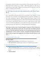
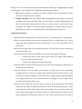
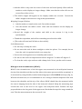
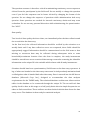
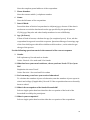
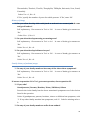
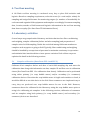
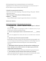
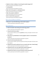
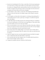
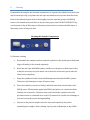
Section B: Performing Anthropometric measurements
The following equipment is needed to perform anthropometric measurements
Digital weighing scale
1. SECA mat for length measurement of very infants
2. Stadiometers for measuring height of the children older than 1 year
3. Gullick inch tape for measuring mid upper arm circumference of the children
Fig 1: Digital weighing scales
Fig 2: SECA Mat (length measurement)
Fig 3: Stadiometer (“height board”)
Fig 4: Gullick inch tape
20
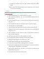
During each visit to the participant’s household the child’s age, length/height, weight
and mid upper arm circumference (MUAC) are measured as follows.
1. Age: Ask the mother or primary care taker about the age of the child and write
down the completed age in months.
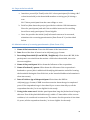
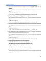
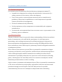
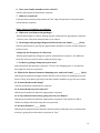
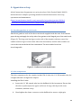
2. Length / Height: If the child cannot stand independently the length is measured
(centimeters) using SECA MAT (Fig 2). If the child can stand independently (as
the case with older children who are close to 2 years of age or more than 85 cms
in length), the height is measured using stadiometers (“height boards”) (Fig 3).
Both the procedures are explained below with illustrations (Fig 5 & 6).
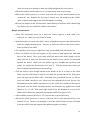
Length measurement:
Place the measuring board on a hard flat surface, i.e. ground, floor, or steady table.
Place the questionnaire and pen on the ground, floor, or table (Arrow 1). Kneel
with both knees behind the base of the board if it is on the ground or floor
(Arrow 2).
Kneel on the right side of the child so that you can hold the foot piece with your
right hand (Arrow 3).
With the mother’s help, lay the child on the board by doing the following:
o
Support the back of the child’s head with your hands and gradually
lower the child onto the board.
o
Support the child at the trunk of the body.
Ask the mother to kneel on the opposite side of the board facing the enumerator to
help keep the child calm.
Cup your hands over the child’s ears (Arrow 4). With your arms comfortably
straight (Arrow 5), place the child’s head against the base of the board so that
the child is looking straight up. The child’s line of sight should be perpendicular
to the ground (Arrow 6). Your head should be straight over the child’s head.
Look directly into the child’s eyes.
Tell the other enumerator that the child is ready to be measured. He /she should
make sure the child is lying flat and in the center of the board (Arrow 7). Place
your left hand on the child’s shins (above the ankles) or on the knees (Arrow 8).
Press them firmly against the board. With your right hand, place the foot piece
firmly against the child’s heels (Arrow 9). For infants, quickly touch the soles of
21
their feet with your thumb to make the child straighten his or her knees.
Check the child’s position (Arrows 1-9). Repeat any steps as necessary.
When the child’s position is correct, read and call out the measurement to the
nearest 0.1 cm. Remove the foot piece, release your left hand from the child’s
shins or knees and support the child during the recording.
Record the length on the questionnaire. Immediately release the child’s head. Help
the child to get up or hand the child to the mother.
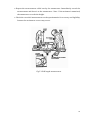
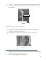
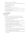
Height measurement:
Place the measuring board on a hard flat surface against a wall, table, tree,
staircase, etc. Make sure the board is stable.
Ask the mother to remove the child’s shoes and upbraid any hair that will interfere
with the height measurement. Ask her to walk the child to the board and to
kneel in front of the child
For mobility, kneel on your right knee only, on the child’s left side (Arrow 3).
Place the child’s feet flat and together in the center of and against the back and
base of the board. Place your right hand just above the child’s ankles on the
shins (Arrow 4) and your left hand on the child’s knees (Arrow 5) and push
against the board. Make sure the child’s legs are straight and the heels and
calves are against the board (Arrows 6 and 7). Tell the enumerator when you
have completed positioning the feet and legs.
Tell the child to look straight ahead at the mother if she is in front of the child.
Make sure the child’s line of sight is level with the ground (Arrow 8). Place your
open left hand on the child’s chin. Gradually close your hand (Arrow 9). Do not
cover the child’s mouth or ears. Make sure the shoulders are level (Arrow 10);
the hands are at the child’s side (Arrow 11); the child’s feet are flat on the base of
the board; and the head, shoulder blades, and buttocks are against the board
(Arrows 12, 13, 14). With your right hand, lower the headpiece on top of the
child’s head. Make sure you push through the child’s hair (Arrow 15).
Check child’s position (Arrows 1-15). Repeat any steps as necessary.
When the child’s position is correct, read and call out the measurement to the
nearest 0.1 cm. Remove the headpiece from the child’s head and your left hand
from the child’s chin and support the child during the recording.
22
Repeat the measurement called out by the enumerator. Immediately record the
measurement and show it to the enumerator. Note: If the assistant is untrained,
the enumerator records the height.
Check the recorded measurement on the questionnaire for accuracy and legibility.
Instruct the assistant to correct any errors.
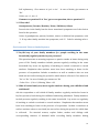
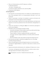
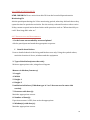
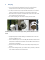
Fig 5: Child length measurement
23
Fig 6: Child height measurement using stadiometer
Weight measurement:
Explaining the Weighing Procedure to the Mother
Show the scale to the mother and explain to her that you are going to weigh her
child on the scale. Older children may be weighed by standing by themselves on
the scale.
Tell her that infants and young children who will not stand on the scale alone will
be weighed while being held by the mother
Ask the mother to dress the child in just light indoor clothing. The children should
not wear thick clothing or anything heavy.
Preparing the Scale
Make sure that the scale is on a smooth surface and make sure that it is flat
(horizontal) and stable.
Weighing Older Children Who Can Stand on the Scale by Themselves
Turn the scale ON by stepping on the scale. The display should show ‘188.8’ first,
and then ‘0.0.’ The ‘0.0’ reading indicates that the scale is ready.
24
Ask the child to step onto the center of the scale and stand quietly. Wait until the
numbers on the display no longer change. Make sure that the solar cells are not
covered by a skirt or feet.
The child’s weight will appear in the display within two seconds. Record the
child’s weight to the nearest 0.1 kg in the questionnaire.
Weighing Younger Children
Ask the mother to stand on the scale. Record her weight.
Give the mother the child to hold. Wait until the numbers on the display no
longer change.
Record the weight of the mother and child to the nearest 0.1 kg in the
questionnaire
Thank the respondent, and tell her something nice about her child.
(The scale will turn itself off after a short while).
Scale Maintenance
Do not drop or bump the scale.
Do not store the scale in direct sunlight or other hot places. For example, do not
leave the scale in a parked vehicle on a sunny day.
Protect the scale against excess humidity and wetness.
Do not use the scales at temperatures below 0 degrees C or above 45 degrees C.
To clean the scale, wipe surfaces with a damp cloth. Never put the scale in water.
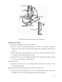
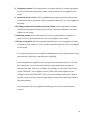
Mid upper arm circumference (MUAC):
MUAC is the circumference of the left upper arm, measured at the mid-point between
the tip of the shoulder and the tip of the elbow (olecranon process and the acromium). It
is measured by using flexible, medical measuring tapes called Gullick inch tape (Fig. 4).
With the left arm bent, it is recommended to use a string to find the midpoint of the arm
between the shoulder and the tip of the elbow. MUAC should then be measured while
the arm is hanging down the side of the body and relaxed. Wrap the measuring tape
around the arm at the level of the upper arm mid-point mark. Position the tape
perpendicular to the long axis of the upper arm. Check that the tape fits snug around the
arm. Take the measurement to the nearest 0.1 cm
25
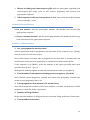
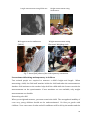
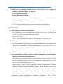
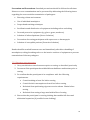
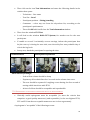
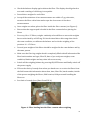
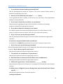
Length measurement using SECA mat
Height measurement using
Stadiometer
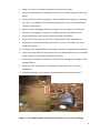
Mid upper arm circumference
Weight measurement using
(MUAC)
Electronic Weighing scale
Fig. 7: Actual field photos of the anthropometry assessment
Precautions while doing anthropometry in children
Two trained people are required to measure a child’s height and length.
When
measuring a child, the field staff member holds the child and takes the measurements.
Another field assistant or the mother helps hold the child while the former records the
measurements on the questionnaire. If two members are not available, only weight
measurements are feasible.
Restraining the child
When you weigh and measure, you must restrain the child. The strength and mobility of
even very young children should not be underestimated. Be firm yet gentle with
children. Your own sense of calm and self-confidence will be felt by the mother and the
26
child.
When a child has contact with any measuring equipment, i.e., on a measuring board you
must hold and restrain the child so the child will not trip or fall. Never leave a child
alone with a piece of equipment.
Maintaining patience while making measurements on the children
Since weighing and measuring requires touching and handling children, normal stress
levels for this type of survey work are higher than for surveys where only verbal
information is collected.
Explain the weighing and measuring procedures to the mother and, to a limited extent,
the child to help minimize possible resistance, fears, or discomfort they may feel.
You must determine whether the child or mother is under so much stress that the
weighing and measuring must stop.
Remember, young children are often uncooperative; they tend to cry, scream, kick, and
sometimes bite. If a child is under severe stress and is crying excessively, try to calm the
child or return the child to the mother before proceeding with the measuring.
Do not weigh or measure a child if:
a. The mother refuses.
b. The child is too sick or distressed.
c. If the child has a physical deformity that will give an incorrect measurement: measure
the child and make a note of the deformity on the survey.
Safety rules
Keep objects out of your hands and pens out of your mouth, hair, or breast pocket when
you weigh and measure so that neither the child nor you will get hurt due to
carelessness. When you are not using a pen, place it in your equipment pack or on the
questionnaire. Make sure you do not have long fingernails. Remove jewelry such as
rings or watches before you weigh and measure.
Section C: Using Child health calendars
Emphasize that you would like the child’s caregiver to focus on the previous 14 days (2
wks)
27
Section 1: Ask Q1. If the caregiver answers NO or Don’t Know, proceed to the next
symptom (Q2).
1. If the caregiver answers YES, proceed to ask about when the symptoms began:
2. Record when the symptoms began. For example, if the caregiver responds “2 days
ago”, you record a “0” and “2” in the first line.
3. Mark an “X” on the day that corresponds to the first day of the symptom. If the first
day was more than 2 weeks in the past, then mark an “X” on day 14.
4. Ask if the child still has the symptom. If YES, then mark an “X” on “Today” and
connect the two Xs with a line. If the child does not still have the symptom, ask how
many days the symptom lasted and count from your original “X” to the end of the
symptoms. Mark and “X” for each day with the symptoms, or connect two Xs with a
line.
Probe to complete the symptom calendar for the past two weeks. If you can, use actual
days of the week (Monday, Tuesday, Wednesday, etc...) to help orient the respondent.
In rare circumstances, a child may have multiple episodes of a symptom over the 14 day
period (see example D on the following page). If you mistakenly record a day with a
symptom where the child did not have the symptom, cross out the incorrect day using a
diagonal line across the box (see example E on the following page).
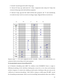
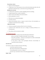
Examples of how to record different symptom responses:
A. Started 2 days ago and child still has symptom.
B. Started 7 days ago and lasted for 5 days.
28
C. Started 3 weeks ago and ended 2 days ago
D. Started 12 days ago and lasted for 3 days. Symptom went away for 5 days, but
returned 4 days ago and child still has symptom.
E. Started 4 days ago and the child still has the symptom. An “X” was mistakenly
recorded on day 5, and is crossed out using a single, diagonal line across the box.
A
B
C
D
E
Repeat steps 1 – 4 for each symptom on the calendar. Collect all the information on a
symptom before proceeding to the next symptom.
IF CHILD HAS HAD CONSTANT COUGH (YES IN Q 2)
Q -8: Measure breathing rates ONLY for children who CURRENTLY have a cough or
difficulty breathing. If the child has clothing that covers his or her chest and stomach,
ask the caregiver to remove the clothing or pull up the clothing so that you can see the
child torso to measure breathing. If the child is crying or visibly upset DO NOT record
the breathing measurement. Only record a breathing measurement when the child is
29
calm and in a resting state. If the child does not calm down for the measurement mark “99” in the answer space. If the child calms down later in the interview, then return to
the question and measure the breathing rate and cross out the “-99”.
To measure the breathing rate, first reset your stopwatch timer. Make sure you have a
clear view of the child’s chest. Start the timer and count the rises of the chest for 30
seconds.
If you observe FEWER than 30 breaths over 30 seconds, record the
measurement in the answer space.
If you observe MORE THAN 30 breaths in 30 seconds, note the first count in the
comments section of the page and repeat the count for another 30 seconds. Record the
repeat count of chest rises you observe in the answer space. If for some reason you
cannot complete the second measurement, record the first measurement in the answer
space.
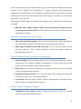
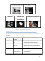
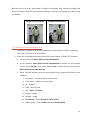
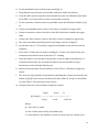
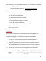
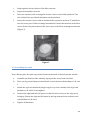
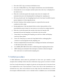
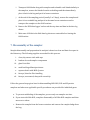
Q -9: During your observation for question Q-8 look for lower chest wall indrawing.
Lower chest wall indrawing (Fig. 9)occurs when the lower chest wall moves in when the
child breathes in; if only the soft tissue between the ribs or above the clavicle goes in
when the child breathes, this is not lower chest wall indrawing
Q – 10: Hear for any whistling sound comes from the child when she inhale or exhale.
Fig 9: In drawing of lower chest wall
Sick Child Protocol
Children with symptoms of ARI (cough or difficult breathing), high breathing rate (= 60
/ min for 0-2 months, =50 / min for 2-12 months, = 40 / min for >12 months), lower
chest wall indrawing, or those who simply look ill or have one or more danger signs
(convulsions, lethargy or unconsciousness, inability to feed, vomiting) will be referred
30
to the nearest primary health centre (PHC) or district health post or SRMC based on the
severity of the condition and feasibility for
further diagnosis and management.
Enumerators should NOT give out medicine or medical advice to the families. Instead
enumerators should advice the family and child’s primary caretaker to seek medical
attention for the sick child.
Enumerators should suggest the family seek medical advice whenever encountering a
sick child.
11. Did any other family member suffer from respiratory infection prior to
current episode of the child?: Ask the question to the mother and encircle the
appropriate response.
Section D: Treatment history for sick child
1. Did you seek medical advice?: This should be asked if any of the symptoms in
the child health calendar is present. Encircle the appropriate response.
2. What type of medical advice did you seek?: If ‘Yes’ was the answer for the
previous question , this question should be asked and answer should be
appropriately encircled.
Section E: Breast feeding, Vaccination, Weaning details
1. Breast feeding: Ask the mother whether she is still breast feeding the child. If
the answer is ‘Yes’ skip Q-1a and go to question no. 2. If ‘No’ was the answer, ask
her how many months she did so and fill response.
2. Bottle fed: Ask the mother whether she is giving any bottle feed to the child and
encircle the appropriate response.
3. Weaning food introduced?: If ‘Yes’ was the answer then further ask when was
it introduce. If ‘No’, go to vaccination question.
4. Vaccinated? Ask the mother whether child is appropriately vaccinated for the
age and encircle the appropriate response.
Section F: Water / Sanitation / Hygiene
1. Cleanliness of the house: Observe whether the house is clean or not and
encircle the appropriate observation
31
2. Cleanliness of the surroundings: Observe whether the surroundings of the
house is clean or not and encircle the appropriate observation
3. Treating water: Ask the mother whether is treating water before drinking
purposes. Here treating means boiling, filtering or any other method of
treatment.
4. Toilet facility: Ask the mother whether the house has a private toilet facility and
encircle the appropriate response.
Once the interview is over, thank the mother / primary care taker for her co-operation
and time spending with you and leave the house.
Notes for analysis of ARI data
ARI: Runny nose or congestion either with or without fever lasting at least 72hours;
being considered a new episode if there was a 48-hour symptom-free interval
Undifferentiated fever: Fever Not associated with other symptoms and lasting for at
least 48 hours
Diarrhea: At least three watery stools in a 24-hour period, being considered a new episode
if there was a 48-hour symptom-free interval
Longitudinal prevalence: The proportion of days on which a given child suffers
symptoms of illness. For e.g. if the child had fever for 2 days in one visit, then the LP is
13.33% (based on a recall period is 15 days (i.e. the total observed days per visit per
child) i.e. 2/15 * 100).
9. Data quality and data management
All study instruments used in TAPHE study are developed by CAR research team based
on the experience in previous air quality and health related projects, through
consultation with various independent and project review committee experts and
through relevant modifications in standardized instruments used in other national and
international studies. These instruments have been piloted and validated before routine
administration in the field.
32
The question structure is therefore critical in maintaining consistency across responses
elicited from the participants by the field staff. Do not modify or change the question
even if you feel the responses can be better elicited by changing the format of the
question. Do not change the sequence of questions while administration. Ask every
question. Some questions are needed for internal consistency checks and may seem
redundant. Do not use any personal discretion while administering the questionnaire.
Use “AS IS”.
Data quality
Two levels of data quality check are done, one immediately after the data collection and
the second after the data entry.
At the first level, the collected information should be verified by the scientists on a
weekly basis and if any data collection errors are suspected, these fields should be
appropriately tagged. Information should be communicated to the field team so that
missing or erroneous data may be collected during subsequent visits to same
household/recruitment location. Once the form is complete, the study instruments
should be stored in an access restricted data storage room after removing the identifier
information as the unique ID is the variable which relates with all study instruments.
Scientists should hand over questionnaires/ field forms to the data entry operators. A
log of what was handed to the data entry team must be independently maintained and
verified gainst what is handed back after data entry. Data is entered into the MS Access
database (Microsoft Corp. Inc.), designed to accommodate the data analyses
requirements for the TAPHE study. The relational database architecture allows various
tables in the database to be connected through the unique ID. The second level data
quality check is done at this stage on a half yearly basis wherein simple frequencies are
taken to find out artifacts. These artifacts are then checked with the data forms for data
entry errors. The database is then ready for statistical analysis.
33
10. References
Management of the child with a serious infection or severe malnutrition : guidelines for
care at the first-referral level in developing countries. World Health Organization.
Integrated Management of Childhood Illness. WHO/FCH/CAH/00.1. Available online:
http://www.who.int/child-adolescenthealth/publications/referral_care/chap3/chap31.htm
34
STANDARD OPERATING PROCEDURES FOR ASSESSING
CHRONIC RESPIRATORY SYMPTOMS AND ASSESSMENT OF
LUNG FUNCTION IN ADULT MEN AND WOMEN
TAPHE-Adult Respiratory Health Study
ICMR-CAR PROJECT
DEPARTMENT OF ENVIRONMENTAL HEALTH ENGINEERING
ICMR CENTER FOR ADVANCED RESEARCH ON
ENVIRONMENTAL HEALTH: AIR POLLUTION
SRI RAMACHANDRA UNIVERSITY
CHENNAI, TN
SOP ID: 2.2- TAPHE-Adult Respiratory Health
Date of issue: 15 April 2010
Date of last review: 19 November 2014
Prepared by
Reviewed by
Approved by
Mrs. Saraswathy
Manivannan
Mr. Rajkumar Paramasivan
Dr. Ashutosh Aggarwal
Dr. Gurusamy Thangavel
Dr. Kalpana Balakrishnan,
Mr. Durairaj Natesan
Dr. Priscilla Johnson
35
1. Purpose and scope
This document provides instructions to research personnel involved in the ICMR-CAR
project for collecting health data pertinent to the Tamil Nadu Air Pollution and Health
Effects-Adult Respiratory Health Study (TAPHE- Adult Respiratory Health Study). It
includes details for (i) screening women and men at the household to assess eligibility
for enrollment in the adult cohort (ii) seeking informed consent (iii) collecting data on
chronic respiratory symptoms and (iv) assessing lung function in eligible women and
men
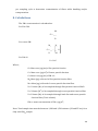
2. Summary of the method
The SOP covers 5 sequential steps (Figure 1) that includes (i) assigning field tasks for
health teams at tool-box meetings (using the Tool Box Information Sheet) (ii) screening
women and men at the household (using Data Form AC 1) (iii) assessment of eligibility
(iv) securing written informed consent (using Data Form AC 2) (v) assessment of
chronic respiratory symptoms through administration of the “INSEARCH” questionnaire
(Data Form AC 3) and (vii) assessment of lung function at the household (Data Form AC
4).
Figure 1: Steps involved in collection of health data in the TAPHE-Adult
Respiratory Health Study
36
3.
Tool Box Meetings
A 10-15min tool-box meeting is conducted every week to plan field activities and
logistics by the scientist in charge. Tasks are spread across the data collection elements
based on weekly, monthly or yearly targets for data collection and availability of field
teams/ vehicles. Check against the Tool Box Meeting Information Sheet for your
assigned task before assembling relevant field materials. Take only required number of
copies of questionnaires or data forms. Document the date, location of field visit, type
and quantity of field equipment in the tool-box meeting data sheet, every day (see Data
Form TB –Information Sheet)
Do not assume a default schedule as the field schedules change frequently and at
short notice.
Prepare a call list based on intended area of visit to inquire about availability of
participant via phone. Include additional households in each list to accommodate
schedule changes. Organize data collection steps based on participant availability as
well as vehicle logistics. Allow sufficient field time to administer lung function tests.
4.
Screening for eligibility at the household ( Data Form
AC 1)
The women and men for the TAPHE –Adult respiratory health study are recruited from
households or communities (i.e. villages/zones) providing participants for the TAPHEBW-ARI Study. While making up the call list for visits to households with M-C cohort
participants (i.e. pregnant mothers/children enrolled in the TAPHE-BW-ARI study),
inquire if the team may approach other men or women from the same household with a
screening questionnaire for participation in the TAPHE-Adult respiratory study. Once,
in the field, if no household members from the M-C are available/ eligible, approach the
nearest available neighbor for recruitment of potential participants with the screening
questionnaire.
37
4.1 Steps at the household
a. Introduce yourself (in Tamil) to the M-C cohort participant (if visiting a M-C
cohort household) or the household member receiving you (if visiting a
nonM-C Cohort participant from the same village or zone.
b. Brief her/him about the project (provide her with the CAR Information
Sheet for participants) and ask if she would be interested in enrolling
herself as a study participant, if found eligible
c. Once she provides the initial (oral) informed consent to be screened,
administer the screening questionnaire (Data Form AC 1) as described
below
4.2 Administration of screening questionnaire (Data Form AC 1)
1. Name of the interviewer: Enter the full name of the interviewer.
2. Date: Record the date of interview in <dd/mm/yyyy> format.
3. Recruiting Household (From MC HH / Neighbour): Write down MC HH, if the
participant is recruited from the mother- child cohort household, else write
down as neighbor.
4. Name of the participant: Write down the full name of the respondent
5. Name of husband / spouse: Write down the full name of the respondent’s
husband or spouse (this is additional identifying information useful for locating
the household during the first field visit, as the household address information is
often inaccurate)
6. Date of birth or Age of the participant: Write down the DOB in
<dd/mm/yyyy> format; if DOB is not known write down the age in completed
years. If the respondent’s age is less than 18 yrs or more than 60 yrs, tell the
respondent that she / he is not eligible for the study.
7. Living in the same area? Ask the participant how long she/he has been living in
this area. Even if they had shifted house(s) within < 5 kms radius of the current
residence, it is considered as same area. The answer for this question is less than
10 years, tell the respondent that she / he is not eligible for the study.
38
8. Pregnancy status: If the respondent is a woman and she is currently pregnant
or not sure about her pregnancy status, tell her that she is not eligible for the
study.
9. Questions from 9 to 11: If the respondent had experienced any of the events
mentioned in these questions, tell the respondent that she / he is not eligible for
the study.
10. Taking treatment for pulmonary tuberculosis: If the respondent is taking
treatment for pulmonary tuberculosis, tell the respondent that she / he is not
eligible for the study.
11. Smoking status: If the respondent is current or past smoker of cigarette or
beedi, tell the respondent that she / he is not eligible for the study.
12. Dusty occupation: Ask the respondent whether she / he is engaged in a dusty
occupation. If the answer is “yes”, tell the respondent that she / he is not eligible
for the study.
For respondents who are not eligible, thank them for their time and answer any
questions they may have regarding their eligibility.
If the respondent is eligible based on responses to questions from 6 to 15, ask
her / him if she / he is interested in being a study participant and sign an
informed consent. If she / he is eligible and willing to participate, encircle the
option ‘INCLUDE’; if not eligible, encircle ‘EXCLUDE’ and if eligible but not
willing, encircle ‘NOT WILLING’. If she / he is not willing, request her / him to
provide a reason and encircle the appropriate answer from the list provided in
the questionnaire.
For participants who are eligible and willing, proceed to secrure informed
consent.
39
5.
Obtaining informed consent from eligible participants at
the household (Data Form AC 2).
5.1 Steps for securing informed consent
1. Provide a consent form (Data Form AC 2) to the participant and request her/him
to get their doubts clarified (if any), once they read it.
2. If he/she cannot read, read it for her/him and make her/him understand the
content of the consent form in the presence of another household member, who
can read Tamil.
3. Get the signature of the participant with full name and date, after the participant
has understood her/his role in the study and voluntarily consents to be a
participant in the study.
4. Obtain a witness signature from the participant’s relative or another field staff
member with full name and date.
5. Complete the interviewer’s statement and sign it with name and date.
6. Give the participant a copy of the signed consent form.
5.2 Assigning a participant ID
All enrolled participants are assigned with a TAPHE unique identifying number to link
all data fields pertaining to the participant and /or household. The assignment of unique
ID is done in the laboratory after securing the informed consent.
Unique ID: This is assigned at the lab. This is a 10 character alpha numeric code which is
assigned by combining three different entities. They are; 1) the type of cohort, 2)
location of cohort and 3) serial number of the cohort participant enrolled in a particular
village/city.
The first character is a text which is either M or A denote the type of cohort – ‘M’ for
mother –child and ‘A’ for adult cohorts. The next 8 digits represent the location of the
cohort; of which the first two characters are texts, which denote either ‘R’ for rural and
‘U’ for urban and ‘K’ for Kancheepuram district or ‘T’ for Thiruvellore district or ‘C’ for
Chennai district. The next six digits of the location component is written in Arabic
numeral which identify the village / zone and the household. The last digit of the unique
ID represents the serial number of the participant of that particular location. For e.g.
M/R/K/001/001/1 means it is a mother- child cohort from the rural area of
40
Kancheepuram district with a village ID 001 and household ID 001 and she is the first
person recruited from the household.
6. Collection of data on chronic respiratory symptoms (Data
Form AC-INSEARCH 3)
This exercise is performed using the INSEARCH (Indian study of the epidemiology of
respiratory symptoms, asthma and chronic bronchitis) questionnaire. The original
questionnaire is directed at diagnosis of asthma, chronic bronchitis (CB), respiratory
symptoms and atopy, based on a validated set of questions without physical
examination. However, the TAPHE adult respiratory study uses the questions to only
estimate the prevalence of chronic respiratory symptoms in relation air pollution
exposures. The study does aim to estimate the prevalence of the disease conditions.
The questionnaire has been validated on individuals of both gender aged above 15 years
irrespective of whether they are from rural or urban locations through direct
administration to the participant. Occasionally, other members of the household
provide information on the age/ date of birth of the participant. It is available in Tamil.
Since the eligibility criteria for TAPHE-Adult Respiratory Health Study excludes
smokers, the detailed section on smoking has been excluded from the original
INSEARCH questionnaire. Therefore the modified questionnaire consists of four
components; 1) demographic and identification details 2) respiratory symptoms, 3)
atopy and family history, and 4) Environmental tobacco smoke exposure.
6.1 Instructions for filling up the Data Form AC INSEARCH 3
General Information
1. Unique ID:
The unique ten digits ID given to each participant should be entered.
2. Date Of Survey
Record the date of interview in <dd/mm/yyyy> format.
3. Name Of The Interviewer:
Enter the full name of the interviewer.
4. Address:
41
Note the complete postal address of the respondent.
5. Phone Number:
Note the contact mobile / telephone number.
6. Name:
Note the full name of the respondent.
7. Date Of Birth:
Record the date of birth of respondent in <dd/mm/yyyy> format. If the date is
not known record the date based on the age specified by the participant as
15/06/yyyy. May also ask other family members in case of difficulty.
8. Age (In Years)
If date of birth is known, calculate the age (in completed years). If not, ask the
respondent his age and record the response. Questions like age of marriage, age
of the first child, age at which first child was delivered etc., can be asked to get
the age of the person.
For the following questions encircle the numeral of the correct response
9. Gender
Self explanatory. Record male or female.
Codes: Encircle 1 for male and 2 for female.
10. What has been your usual residence, where you have lived >75% of your
life?
Emphasize the term ‘Usual’.
Codes: Encircle 1 for rural and 2 for urban.
11. For how many years have you received education?
To calculate the number of years of education, sum the number of years spent in
school and college (if applicable). Record ‘0’ if the respondent has never formally
been to school.
12. What is the occupation of the head of household?
Select a single option that best describes the occupation of the head of the
household as told by the participant.
13. What is your occupation?
Select a single option that best describes the occupation of the respondent.
42
Breathlessness and Tightness of Chest
14. Have you ever had wheezing or whistling sound from your chest during the
last 12 months?
Self explanatory. Give answer in ‘Yes’ or ‘No’. In case of doubt, give answer as
‘No’.
Codes: Yes = 1, No = 0.
If ‘Yes’, specify the number of years for which present. If ‘No’, enter ‘99’.
15. Have you ever woken up in the morning with a feeling of tightness in the
chest or of breathlessness?
Self explanatory. Give answer in ‘Yes’ or ‘No’. In case of doubt, give answer as
‘No’.
Codes: Yes = 1, No = 0.
If ‘Yes’, specify the number of years for which present. If ‘No’, enter ‘99’.
Shortness of breath
16. Have you ever felt shortness of breath after finishing exercises, sports or
other heavy exertion during the last 12 months?
Self explanatory. Give answer in ‘Yes’ or ‘No’. In case of doubt, give answer as
‘No’.
Codes: Yes = 1, No = 0.
If ‘Yes’, specify the number of years for which present. If ‘No’, enter ‘99’.
17. Have you ever felt shortness of breath when you were not doing some
strenuous work during the last 12 months?
Self explanatory. Give answer in ‘Yes’ or ‘No’. In case of doubt, give answer as
‘No’.
Codes: Yes = 1, No = 0.
If ‘Yes’, specify the number of years for which present. If ‘No’, enter ‘99’.
18. Have you ever had to get up at night because of breathlessness during the
last 12 months?
Self explanatory. Give answer in ‘Yes’ or ‘No’. In case of doubt, give answer as
‘No’.
Codes: Yes = 1, No = 0.
If ‘Yes’, specify the number of years for which present. If ‘No’, enter ‘99’.
43
Cough and Phlegm
19. Have you ever had to get up at night because of cough during the last 12
months?
Self explanatory. Give answer in ‘Yes’ or ‘No’. In case of doubt, give answer as
‘No’.
Codes: Yes = 1, No = 0.
If ‘Yes’, specify the number of years for which present. If ‘No’, enter ‘99’.
20. Do you usually cough first thing in the morning?
Self explanatory. Give answer in ‘Yes’ or ‘No’. In case of doubt, give answer as
‘No’.
Codes: Yes = 1, No = 0.
If ‘Yes’, specify the number of years for which present. If ‘No’, enter ‘99’.
21. Do you usually bring out phlegm from your chest first thing in the morning?
Self explanatory. Give answer in ‘Yes’ or ‘No’. In case of doubt, give answer as
‘No’.
Codes: Yes = 1, No = 0.
If ‘Yes’, specify the number of years for which present. If ‘No’, enter ‘99’.
22. Do you usually bring out phlegm from your chest most of the morning for
at least 3 consecutive months during the year?
Self explanatory. Give answer in ‘Yes’ or ‘No’. In case of doubt, give answer as
‘No’.
Codes: Yes = 1, No = 0.
If ‘Yes’, specify the number of years for which present. If ‘No’, enter ‘99’.
23. Select the most appropriate out of the following
(a) I hardly experience shortness of breath.
(b) I usually get shortness of breath but always get well
(c) My breathing is never completely satisfactory
Self explanatory. Give Select the most appropriate choice.
Codes: (a) = 0, (b) = 1, (c) = 2.
If the answer is (b) or (c), specify the number of years for which present; else
enter ‘99’.
44
Reaction to exposure to dust/ animals
24. When you are exposed to dusty areas, or pets like dog, cat or horse, or
feathers or quilts or pillows, etc., do you
(a) Feel tightness in chest?
(b) Feel shortness of breath?
Self explanatory. Give answer in ‘Yes’ or ‘No’, separately for each of (a) and (b) in
case of doubt, give answer as ‘No’
Codes: Yes = 1, No = 0.
If ‘Yes’, specify the number of years for which present. If ‘No’, enter ‘99’.
History of Asthma
25. Have you ever suffered from asthma?
Self expalanatroy. Ask if the diagnosis was made by a doctor. Give answer in
‘Yes’ or ‘No’. In case of doubt, give answer as ‘No’.
Codes: Yes = 1, No = 0.
If ‘Yes’, specify the number of years for which present. If ‘No’, enter ‘99’.
26. Have you ever had an attack of asthma during the last 12 months?
An attack of asthma means rapid worsening in breathlessness requiring increase
in the dose of medicines or requiring hospitalization. Give answer in ‘Yes’ or
‘No’. In case of doubt, give answer as ‘No’.
Codes: Yes = 1, No = 0.
If “Yes”, specify the number of years for which present. If ‘No’, enter ‘99’.
27. Are you taking any inhaler, pump, rotahaler, nebulizer, or bronchodilator
tablets for treatment of breathlessness?
Self explanatory. The bronchodilator tablets should be one from the list given
below or identified with the help of local practitioner. Give answer in ‘Yes’ or
‘No’. In case of doubt, give answer as ‘No’.
(Bronchodilator tablets include: Albutamol, Ambro, Aminophyllin, Asmanil,
Asmatide, Asthalin, Bambudil, Betaday, Betasma, Biryth, Bricanyl, Broncophyl,
Broncure, Bronkomed, Bronkoplus, Bronkotab, Brosmin, Carbasma, Curamol,
Deriphyllin, Duralyn, Durasal, Eloxin, Etophylate, Etosal, Lungful, ODPhylin,
Phylobid, Relasmin, Remetuss, Salbetol, Salbouxine, Salbutamol, Salmaplon,
Salphylate, Salvent, Slowthyline, Somavent, Terbutaline, Tergil, Terfex,
45
Theoasthalin, Theobric, TheoPA, Theophyllin, TRPhylin, Unicontin, Vent, Ventil,
Ventorlin).
Codes: Yes = 1, No = 0.
If ‘Yes’, specify the number of years for which present. If ‘No’, enter ‘99’.
History of Atopy
28. Do you often develop skin rash (such as urticaria or eczema) which come
and go off and on?
Self explanatory. Give answer in ‘Yes’ or ‘No’. In case of doubt, give answer as
‘No’.
Codes: Yes = 1, No = 0.
29. Do you often develop sneezing or running nose?
Self explanatory. Give answer in ‘Yes’ or ‘no’. In case of doubt, give answer as
‘No’.
Codes: Yes = 1, No = 0.
30. Do you often develop itchiness in eyes?
Self explanatory. Give answer in ‘Yes’ or ‘No’. In case of doubt, give answer as
‘No’.
Codes: Yes = 1, No = 0.
Family history of asthma/atopy
31. Do any of your family members have any of the above three symptoms?
Self explanatory. Give answer in ‘Yes’ or ‘No’. In case of doubt, give answer as
‘No’.
Codes: Yes = 1, No = 0.
If answer to question 31 is ‘Yes’, go to next question, else to question 33.
32. If yes, who?
Grandparents/ Parents/ Brother/ Sister/ Children/ Others
Record who in the family has the above-mentioned symptoms out of the choices
listed in the question.
Codes: If grandparents, parents, brothers, sisters or children has symptoms, code
‘1’. If any other family member has symptoms, code ‘0’. Code for missing value =
0.
33. Do any of your family members suffer from asthma?
46
Self explanatory. Give answer in ‘yes’ or ‘no’. In case of doubt, give answer as
‘No’.
Codes: yes = 1, no = 0.
If answer to question 33 is ‘Yes’, go to next question, else to question 35.
34. If Yes, who?
Grandparents/ Parents/ Brother/ Sister/ Children/ Others
Record who in the family has the above-mentioned symptoms out of the choices
listed in the question.
Codes: If grandparents, parents, brothers, sisters or children has symptoms, code
‘1’. If any other family member has symptoms, code ‘0’. Code for missing value =
0.
Environmental Tobacco Smoke Exposure
35. Do/did any of your family members (i.e. people residing in the same
household) regularly smoke in your presence?
This question aims at assessing exposure to passive smoke at home during early
years of life. Family members include persons regularly residing in the same
household. Lay stress on regularity of smoking to exclude occasional or casual
smokers. Emphasize that smokers must have been smoking at home in the
presence of respondent. Include ex-smokers as well as smokers who are now
dead, but were alive during the period for which data is collected. Give answer in
‘Yes’ or ‘No’. In case of doubt, give answer as ‘No’.
Codes: Yes = 1, No = 0, Missing Value = 99.
36. Who all in the family are/were regular smokers during your childhood and
adulthood?
Ask the respondent to tell which all family member regularly smoked at home in
his/her presence, both during his childhood and during adulthood. Family members
include persons regularly residing in the same household. Lay stress on regularity
of smoking to exclude occasional or casual smokers. Emphasize that smokers must
have been smoking at home in the presence of respondent. Include ex-smokers as
well as smokers who are now dead, but were alive during the period for which data
is collected.
For married women, replace father, mother and siblings with
corresponding relatives of husband while recording family members during
47
adulthood. Tick each relative appropriately as ‘Yes’ or ‘No’. In case of doubt, record
‘No’. After the respondent has enumerated his response, specifically ask for the
relatives whose data is still missing. For relatives not listed among choices, select
‘Others’ and mention the relationship.
Codes: Yes = 1, No = 0, Missing value = 99.
For each answer recorded as ‘Yes’ , ask the respondent about the main smoked
tobacco product he/she was exposed to, as well as the number of hours of daily
exposure and the approximate number of years for which this exposure occurred.
Use codes for tobacco product: Cigarette = 1, Bidi = 2, Hookah =3, Cigar = 4, Pipe = 5,
Others = 6.
For each answer recorded as ‘No’ fill up ‘99’ in each of ‘Products’, ‘Hours per day’
and ‘Years’.
Finish the interview by thanking her/him for their valuable time to complete the
questionnaire
7. Assessing pulmonary function by spirometry (Data Form
AC 4)
Field staff involved in administration of lung function tests in the TAPHE Adult
Respiratory Health study must undergo the spirometry certification program conducted
by the Department of Chest Medicine of Sri Ramachandra Hospital.
7.1 Requirements for equipment
Note: The instructions provided in the SOP are specifically directed at using the KOKO
spirometer although it is applicable across other comparable instruments
1. Laptop (with KoKo software installed), power cord and mouse
2. Spirometer with connecting USB cable .
3. Connecting piece (between pneumotach and mouthpiece)
4. Disposable Mouthpiece
5. 3 Liter calibration syringe .
6. Connecting piece (between syringe and pneumotach) with filter
7. Stadiometer / tape for measuring height, scales for weight.
8. Bronchodilator administration: Inhaler, Spacer, Mouthpiece
48
KoKo
Spirometer connected to
Spirometer/Pneumotach
laptop
Mouthpiece
Connecting piece
Pneumotach with Mouthpiece
(between pneumotach
and mouthpiece)
Figure 1: Spirometer and accessories
7.2 Definitions
The following standard definitions/criteria are used for parameters recorded using the
spirometer
Abbreviation
Parameter ,
Definition / Explanation / Details
( units)
VC
Vital capacity, litres
(L)
FVC
Forced vital capacity,
litres (L)
The volume change between the position of full
inspiration and complete expiration
The maximal volume of air exhaled with
maximally forced effort from a position of
maximal inspiration
FEV1
FEV1/
Forced expiratory
The maximal volume of air exhaled in the first
volume in one
second of a forced expiration from a position
second, litres (L)
of full inspiration.
Forced expiratory
The ratio of FEV1 to FVC expressed as a
49
FVC
volume in one second
percentage
to forced vital
capacity ratio
FEF25-75%
PEF
TLC
Forced mid-
The average flow measured over the middle
expiratory flow litres
50% of an FVC maneuver. Also known as mid
per second (L.s-1)
expiratory flow
Peak expiratory flow
The maximum expiratory flow achieved from a
litres per second (L.s-
maximum forced expiration, starting without
1) or litres per
hesitation from a point of maximal lung
minute (L.min-1)
inflation
Total lung capacity,
litres (L)
The volume of gas in the lungs after maximal
inspiration, or the sum of all volume
compartments
Definition/Explanation
Acceptability Criteria
Satisfactory start, middle and end of test
conditions
Closeness of agreement between the
results of successive measurements of
the same maneuver carried out, subject
Repeatability Criteria
to all of the following conditions: same
method, same observer, same
instrument, same location, same
conditions of use, and repeated over a
short space of time
7.3 Screening Checklist for PFT (Use Data Form AC 4)
Contraindications for performing spirometry
Some conditions may pose a relative danger to a participant or affect the validity of
spirometry performance and results. These include, but are not limited to, the following:
50
Unstable cardiovascular status, unstable angina, recent myocardial infarction
(within one month), or pulmonary embolism
Haemoptysis of unknown origin
Recent pneumothorax
Thoracic, abdominal, or cerebral aneurysms
Recent thoracic, abdominal or eye surgery
Acute disorders such as nausea or vomiting
Severe respiratory distress
Physical limitations
Cognitive impairment or dementia.
The above mentioned contraindications should be ruled out with the help of a validated
check list before performing the test (Data Form AC 4). PFT assessments should not be
performed on participants reporting one or more of the conditions listed.
7.4 Spirometer Calibration
Calibration
To ensure that the spirometer is in good working condition and the data generated
during testing is accurate, the spirometer is calibrated once a day prior to performing
the tests
Calibration syringe (General instructions):
The calibration syringe should be stored at the same temperature and humidity
as the testing site, away from direct sunlight and heat sources. This is best
achieved by storing the syringe close to the spirometer.
A calibration syringe should be used to check the volume calibration of
spirometers and must have an accuracy of ±15mL or 0.5% of the full scale,
whichever is greater. For most spirometers the syringe volume required is 3L.
A calibration syringe should be validated yearly to ensure accuracy. For specific
details refer to the manufacturer‟s recommendations.
A calibration syringe should be checked monthly for leaks by attempting to
empty it with the outlet occluded. This should be performed at more than one
volume.
51
Perform inspection of adjustable or variable stops, if they exist, especially if the
syringe has been dropped or damaged.
Use of the syringe on a large number of machines distinguishes between
instrument problems and problems with the syringe.
To perform calibration:
Pneumotach is connected to the laptop, and the Calibration syringe to the inlet
port of the pneumotach as shown below
Figure 2: Calibration assembly
Click on the icon “Calibrate” in the Spirometry Software
Verify and change if necessary, the environmental conditions (room
temperature, Atmospheric pressure and relative humidity).
Enter the name of the person performing calibration.
Select the syringe volume (3L). Click on Setup/MultiFlow syringe.
Calibration can be started by clicking Test/Start calibration. (This procedure will
begin null‟ing the Pneumotach. During nulling, it must be ensured that there is
no air flow through the Pneumotach.) Perform at least 3 trials with varying flow
rates for each effort by pushing the syringe handle. NSPIRE HEALTH
recommends using Low flow, Medium flow and High flow.
When calibration has been successfully completed, a message will come on the
screen informing that “Pneumotach calibration is adjusted and now within
tolerance”. Click on OK.
A print of the report of calibration graphic results prior to exiting the calibration
screen can also be done if required by Clicking on the Print icon.
52
7.5 Spirometry (Main )Procedure
7.5.1 PREPARING THE SPIROMETER
(as outlined in the ATS pulmonary function laboratory management manual 7)
Assemble the components according to the manufacturer’s instructions (i.e.
tubing, connectors, flow-sensors, valves and adapters).
Turn on the system to ensure adequate warm up (refer to manufacturer’s
guidelines). Allow time for equilibration to room temperature for portable
systems (for field level investigations).
Perform a validation check (calibration)
Perform spirometry only at temperatures recommended by the equipment
manufacturers.
Document the environmental data from an accurate source representative of the
laboratory prior to calibration.
7.5.2 INFECTION CONTROL
The aim of infection control is to provide a better understanding of infections and their
modes of transmission to the staff and the participants. It is also important in
maintaining a safe working environment for staff and participants to help prevent
disease transmission during pulmonary function testing. ATS/ERS guidelines define
direct and indirect contact with respect to pulmonary function testing and transmission
of pathogens as follows:
Direct contact: (From person to person) There is potential for transmission of upper
respiratory tract disease, enteric infections, and blood-borne infections through direct
contact. Although hepatitis and HIV transmission are unlikely via saliva, disease
transmission is a possibility when there are open sores on the oral mucosa, bleeding
gums, or haemoptysis. The most likely surfaces for contact are mouthpieces and the
immediate proximal surfaces of valves or tubing.
Indirect contact: (via animate and inanimate objects) There is potential for transmission
of TB, various viral infections, and possibly, opportunistic infections and nosocomial
pneumonia through aerosol droplets. The most likely surfaces for possible
contamination by this route are mouthpieces and proximal valves and tubing.
53
Prevention and Precautions: Standard precautions should be followed at all times.
Disease or cross contamination can be prevented by addressing the following issues
regarding the source and the transmission of pathogens:
Ensuring a clean environment
Use of individual mouthpiece
Proper hand-washing techniques
Sterilisation and disinfection of equipment including valves and tubing
Personal protective equipment (e.g. gloves, gown, masks etc)
Isolation of infected patients (Source Isolation)
Precautions for testing participants with open sores or haemoptysis
Isolation of susceptible patients (Protective Isolation).
Hands should be washed between tests and immediately after direct handling of
mouthpieces, tubing, breathing valves or the interior surfaces of equipment to prevent
transmission of disease pathogens.
7.5.3 PREPARING THE PARTICIPANT
1. Carry out infection control measures prior to testing as described previously.
2. Document if the participant has withheld bronchodilator medications prior to
testing.
3. Re-confirm that the participant is in compliance with the following
requirements:
Ceased smoking at least 1hr before testing
Ceased alcohol consumption at least 4 hrs before testing
Refrained from performing vigorous exercise atleast 30min before
testing
Refrained from eating a large meal within 2hrs of testing
4. Ensure that the participant is wearing clothing that enables full chest and
abdominal expansion (if possible loosen clothing).
54
5. Record relevant medical history that may assist in the interpretation/reporting
of spirometry. This may include the following symptoms assessed previously
using the Data Form AC INSEARCH 3.
Breathlessness
Cough
Sputum
Wheeze
Symptoms of asthma
Smoking history (years, packs/day, current status)
Known lung disease/chest injuries/operations
Work history
Occupational exposure to dust and respiratory irritant
6. Clearly instruct the participant about the procedure prior to the commencement
of each test and ensure that the participant understands all requirements of the
test. Give ample opportunity for the participant to ask questions or receive
clarification on the test and its requirements.
If the participant is found to be eligible for the Spirometry Test, proceed further.
7.5.4 BRONCHODILATOR ADMINISTRATION
Recommended dose of 4 puffs of Asthalin is given to all participants 15 minutes prior to
the test maneuver. It can be safely used in the field. Spacer is recommended for proper
delivery of the medicine. The mouth piece of the spacer should be cleaned using a
disinfectant at the field before it is used for the next participant.
7.5.5 MEASURING HEIGHT AND WEIGHT
Measure and record the participant’s height (barefoot) in centimetres (cm), with feet
together, heels against the wall, standing as tall and straight as possible and with the
head in the horizontal plane (eyes level and looking ahead). Measure the participant’s
height by placing a hard board or scale firmly above the head, mark the point on the
wall and read the lower end of it using a measuring tape.
55
Measure and record the participant’s weight in kilograms (kg) standing straight and
without footwear. Restrict participant touching or leaning on anything and obstructing
the display.
Height measurement
Weight measurement
7.5.6 ENTERING PARTICIPANT INFORMATION:
1. Establish a rapport with the participant by self-introduction and by explaining
how easy is the test to be performed.
2. Enter the following information on to the home window of KoKo PFT software.
Click on the icon Enter/Edit Patient Information
In the window Enter/Edit Patient Information, towards the left bottom
corner under Patient, click on the button New… which will open the window
Enter Participant Information.
Enter relevant details about the participant in the appropriate fields of the
window:
i. Last name – the participant’s actual name
ii. First name – initials or second name
iii. ID – ICMR ID
iv. DOB – Date of birth
v. Sex – Male or Female
vi. Height – in cm
vii. Weight – in kg
viii. Predicteds – Select Knudson 1976/1983
ix. Ethnic group – Select Other and then South Indian
56
3. Then click on the button More… which will open the window for Additional
Patient Information and add the following details:
a. Address – Locality, District, State
Note: Now, if a dialogue box Patient Information pops up with the message “The
patient’s age, height, or weight is outside of the published range for the selected
predicted equation set. Predicted values can still be calculated through
extrapolation. Do you want predicted values calculated this way for the patient,”
click the button Yes.
4. It will lead to the window Enter/Edit Patient Information showing only the
current participant’s details; now click on the button Close; it will lead to the
specific record for that participant in the home window.
7.5.7 STARTING THE TEST
1. Click on the icon Perform FVC Test on the home window, which will open a
window FVC Test with the predicted plot (pink squares).
2. Now get back to the participant
a. Position the participant appropriately (as mentioned below).
b. Demonstrate the procedure once.
c. Perform the test
Positioning the Participant
1. Ask the participant to loosen tight clothing and waist belt, if any.
2. Ask the participant to stand comfortably.
3. Explain and demonstrate the test maneuver to the participant, including:
Correct use of mouthpiece
Correct posture with head slightly elevated
Position of the mouthpiece, including tight mouth seal over the
mouthpiece.
Complete inhalation prior to FVC and FEV1
Rapid and complete exhalation with maximal force for FVC and FEV1.
4. Ask the participant to sit in front of you looking away from the recording.
Note: The technician’s Position should be in such a way that the air blown out by
the participant through the pneumotach does not hit his/her face or body
directly.
Demonstration of test
57
There are 3 distinct phases to the FVC maneuver, as follows:
1) Maximal inspiration;
2) A ‘‘blast’’ of exhalation; and
3) Continued complete exhalation to the end of test (EOT).
Demonstrate all the 3 phases.
Performing the test
Tear open the cover from the side with a ‘cut’ and take out a fresh mouth piece in
front of the participant and fit it to the pneumotach and hand it over to the
participant.
Guide the participant in placing the mouthpiece properly and instruct the
participant to close the lips tightly around the mouthpiece
Instruct the participant to perform the test only upon indication; tell that he/she
should not even take the pneumotach near the mouth before asking him/her ‘to
start’.
Activate the spirometer by clicking the Start icon and Instruct participant to
position the mouthpiece.
Immediately after positioning the mouthpiece firmly,
-
instruct the participant to inhale deeply (as much as possible) until the lungs
get filled completely; at the end of inhalation,
-
instruct him/her to exhale as rapidly and forcibly as possible, and
-
encourage continued complete exhalation (≥6 seconds) until the end of the
test (EOT),
After EOT ask him to take a deep breath once again and complete the test.
Encourage the participant to maintain an upright posture (i.e. no bending
forwards) during the maneuver.
Observe the participant at all times during the maneuver in case they become
unsteady due to light-headedness or experience other adverse reactions, such as
chest pain.
Repeat the instructions and maneuvers for a minimum of 3 maneuvers, or more
if necessary, coaching vigorously until the end of test criteria are met; no more
than eight maneuvers should be usually performed.
Note: Give him/her a rest of 3 to 5 minutes in between the trials.
58
Then click on the icon Test Information and enter the following details in the
window that opens:
-
Technician – Your name
-
Test Site – Local
-
Participant position – Sitting/standing
-
Comments – select any one from the drop-down list, according to the
participant’s performance
-
Then click OK which will close the Test Information window
Then close the window FVC Test.
It will lead to the window KoKo PFT System, for another test for the next
participant.
If unable to record 3 technically correct tracings, inform the participant that
he/she can try it during the next visit; note down his/her next probable day of
visit in the log book.
In any case, thank the participant for sparing the time.
Demonstration
Participant Performance
Observation of tracings:
-
Peak of flow volume should be sharp
-
Expiratory effort should last for 6 seconds in the volume-time curve
-
The test should be repeated if coughing occurs during the first second of
tracing which interferes with FEV1
-
At least 3 efforts should be acceptable and reproducible
7.5.8 DETERMINING ACCEPTABILITY AND REPEATABILITY OF MEASUREMENTS
Clinically useful spirograms must be acceptable (i.e meet the criteria that
comprises a good quality maneuver) and repeatable (i.e the two highest FEV1,
FVC and VC from three acceptable maneuvers are in close agreement).
A spirogram is “acceptable” if the following are met:
59
Start of test criteria
Begins from full inspiration
A rapid start of test. If the maneuver has an obviously hesitant start then the trial
should be terminated early to avoid unnecessary prolonged effort.
Middle of test criteria
No obstruction, hesitation or artifact impeding the blow including:
Cough during the first second of exhalation
Glottic closure that influences the measurement
Early termination or cut-off
Effort that is not maximal throughout
Air leaks at mouth
Obstructed mouthpiece (due to tongue or teeth in front of the mouthpiece, or
mouthpiece deformation due to biting)
End of test criteria
Continuous maximal expiratory blow for ≥6 sec in duration
A plateau in the volume-time curve (i.e. no change in volume (<0.025L) for a 1
second period)
The patient need not continue to exhale.
7.5.9 TERMINATION OF TEST
Conclude the session after arriving at any of the following circumstances
-
After successfully recording 3 technically correct tracings
-
Even after repeated (6 – 8) trials, the participant is not able to understand
and/or perform the test properly
-
At any point of time, if the participant becomes inconvincibly uncooperative and/or hesitant
Interferences
If erroneous results are obtained, check the following:
—
Is the filter attached correctly?
—
Has the pneumotach been calibrated lately?
—
Is the pneumotach screen free of debris?
—
Are there any restrictions to the air flow through pneumotach?
Read / Print
60
Select Read/Interpret. The screen will show the format which ever report
design is currently selected.
Select Patient and Test Series
To show the report of a particular test group, select Read / Interpret /File /
Select Patient and Test Series.
Select the desired group and click on OK.
To print a report, make sure to indicate the settings desired in File/Print setup
from the “Read/Interpret/Print results” screen.
8. Data quality and data management
All study instruments used in TAPHE study are developed by CAR research team based
on the experience in previous air quality and health related projects, through
consultation with various independent and project review committee experts and
through relevant modifications in standardized instruments used in other national and
international studies. These instruments have been piloted and validated before routine
administration in the field.
The question structure is therefore critical in maintaining consistency across responses
elicited from the participants by the field staff. Do not modify or change the question
even if you feel the responses can be better elicited by changing the format of the
question. Do not change the sequence of questions while administration. Ask every
question. Some questions are needed for internal consistency checks and may seem
redundant. Do not use any personal discretion while administering the questionnaire.
Use “AS IS”. The printed hard copies PFT reports should be sent to chest physician for
interpretation and approval. The hard copies are then filed in a secured storage area.
Two levels of data quality check are done, one immediately after the data collection and
the second after the data entry. At the first level, the collected information should be
verified by the scientists on a weekly basis and if any data collection errors are
suspected, these fields should be appropriately tagged. Information should be
communicated to the field team so that missing or erroneous data may be collected
during subsequent visits to same household/recruitment location. Once the form is
complete, the study instruments should be stored in an access restricted data storage
room after removing the identifier information as the unique ID is the variable which
relates with all study instruments.
61
Scientists should hand over questionnaires / field forms to the data entry operators. A
log of what was handed to the data entry team must be independently maintained and
verified against what is handed back after data entry. Data is entered into the MS Access
database (Microsoft Corp. Inc.), designed to accommodate the data analyses
requirements for the TAPHE study. The relational database architecture allows various
tables in the database to be connected through the unique ID. The second level data
quality check is done at this stage on a half yearly basis wherein simple frequencies are
taken to find out artifacts. These artifacts are then checked with the data forms for data
entry errors. The database is then ready for statistical analysis.
For PFT data attention to equipment quality control and calibration is an important part
of good laboratory practice. At a minimum, the requirements are as follows:
1) A log of calibration results should be maintained;
2) Documentation of repairs and/or other alterations which return the equipment to
acceptable operation should be done; and
3) The dates of computer software and hardware updates or changes, calibration checks
and quality-control procedures must be repeated before further testing begins
References
1. American Thoracic Society. Pulmonary Function Laboratory Management and
Procedures Manual. 1st ed: American Thoracic Society; 1994.
2. Jindal, S. K, Aggarwal, A. N, Gupta, D., Agarwal, R., Kumar, R., Kaur, T., Chaudhry,
K. Shah, B., Indian Study on Epidemiology of Asthma, Respiratory Symptoms and
Chronic Bronchitis in adults (INSEARCH), The International Journal of
Tuberculosis and Lung Disease, 16(9): 2012, pp. 1270-1277(8).
3. Miller MR, Crapo R, Hankinson J, Brusasco V, Burgos F, Casaburi R, et al. General
considerations for lung function testing. Eur Respir J. 2005 Jul;26(1):153-61.
4. Miller MR, Hankinson J, Brusasco V, Burgos F, Casaburi R, Coates A, et al.
Standardisation of spirometry. Eur Respir J. [Practice Guideline]. 2005
Aug;26(2):319-38.
5. Queensland Guideline for Spirometry (Adult) Respiratory Science, Document
Number # QH-GDL-386:2012.www.inspirehealth.com
62
STANDARD OPERATING PROCEDURE FOR SAMPLING AND
ANALYSIS OF PARTICULATE MATTER (PM) IN HOUSEHOLD
MICRO-ENVIRONMENTS
TAPHE-EXPOSURE STUDY
ICMR-CAR PROJECT
DEPARTMENT OF ENVIRONMENTAL HEALTH ENGINEERING
ICMR CENTER FOR ADVANCED RESEARCH ON
ENVIRONMENTAL HEALTH: AIR POLLUTION
SRI RAMACHANDRA UNIVERSITY
CHENNAI, TAMIL NADU
SOP ID: 2.3- TAPHE_EXPOSURE - PM
Date of issue: 15 April 2010
Date of last review: 19 November 2014
Prepared by
Reviewed by
Dr. Naveen Puttaswamy
Dr. Sankar Sambandam
Mr. Arulselvan
Sadasivam
Dr. Krishnendu
Mukhopadhyay
Approved by
Dr. Kalpana Balakrishnan
Ms. Amudha Natarajan
Mr. Venkatesan Doss
63
1. Purpose
This document provides instructions for collection and determination of particulate
matter (PM) mass concentrations for the purpose of estimating household microenvironment PM concentrations and exposures concentrations following protocols
developed by NIOSH method 0600 and standard procedures developed by
Environmental Health Sciences division, School of Public Health, University of
California, Berkeley and RTI International (NIOSH, 1998; UCB, 2005; RTI 2008).
2. Scope and Applicability
This document provides instructions to collect and determine PM mass concentrations
in household micro-environments. It also outlines procedures for estimation of PM
exposure concentrations using gravimetric (method 1) and real-time UCB particle
monitor (method 2) measurements. These procedures are developed with specific
modifications that are based on recommendations of manufacturers of locally available
equipments and requirements related to field conditions (i.e. indoor and near-outdoor
sites).
3. Summary of procedures
The SOP for PM collection and analysis involves four major steps, grouped under i) toolbox meeting, ii) laboratory activities, iii) field activities, iv) quality check & data entry,
and v) data analysis (Fig. 1). Each of these activities is described in detail in the
following sections.
Figure 1: Steps involved in collection and determination of PM mass concentration
64
4. Tool-box meeting
A 10-15min tool-box meeting is conducted every day to plan field activities and
logistics. Based on sampling requirement, select the areas (i.e. rural and/or urban) for
sampling and assign field teams. Set monitoring targets (i.e. number of households) for
each team and organize field equipments and samplers accordingly. Document sampling
date, location, number of field teams and logistics information in the tool-box meeting
data sheet everyday (Use Data Form TB Information Sheet).
5. Laboratory activities
Several steps are grouped under laboratory activities that involves filter conditioning
and weighing, sampler calibration (before and after sampling) and preparation of
sampler units for field sampling. Divide the work load among field team members to
complete each step prior to going to field. Typically, filter conditioning and weighing
should be handled by an experienced personnel to maintain consistency in operations
and minimize bias introduced due to inter-person variation. Each of these steps are
explained in detail in the following sections.
5.1
Sampler calibration (Data Form EXP 1 and EXP 2)
Calibrate all air samplers before and after of each field sampling day and enter the
calibration data along with information on date, sampler ID and flow-rate in calibration
sheets (Use Data Form EXP 1 for calibration data sheets). Calibration can be performed
using either primary (i.e. soap bubble meter) and/or secondary (i.e. rotameter)
calibration devices. Given that the soap bubble meter is fragile and sensitive to shock, it
would be difficult to use this device in the field. Since rotameters are simple and easy to
carry, they are preferred over soap bubble meters for use in the field. However,
rotameters has to be calibrated in the laboratory using the soap bubble meter prior to
using it for calibrating air samplers. In the following sections, calibration of rotameter
and air samplers using both primary (i.e. soap bubble meter) and secondary (i.e.
rotameter) devices are described.
65
5.1.1 MATERIALS REQUIRED
a. Air sampler (SKC 224-PCXR8)
b. SKC pump charger
c. 1000ml inverted standard glass burette (frictionless)
d. Burette stand with clamp
e. BGI triplex cyclone with calibration chamber
f. Rotameter (Matheson-TriGas)
g. Beaker (100ml)
h. Soap solution (diluted)
i.
Standard calibrated Stop watch
j.
Filter cassette (Three stage, 37 mm PTFE filter, 0.8μm pore size)
k. Filter cassette holder
l.
PVC luer taper connector
m. Flexible tubing
n. Screw driver
o. Calculator
p. Calibration form
q. Air leak checking instrument
5.1.2 ROTAMETER CALIBRATION USING SOAP-BUBBLE METER
a. Thoroughly wash the standard glass burette in and out with water
66
b. Fix the washed burette in the burette stand (Fig. 2)
a. Keep diluted soap solution in the beaker, and place under the burette.
b. Clean the BGI cyclone separator and assemble the unit for calibration (Use Data
Form EXP 2 for instructions to clean and assemble cyclones)
c. Fix the rotameter in between the soap bubble meter & calibration chamber (Fig.
2)
d. Connect soap bubble meter outlet to the inlet of rotameter by tygon tube.
e. Connect rotameter outlet to the inlet of the BGI calibration chamber by tygon
tube.
f. Connect the filter cassette outlet to the inlet of the air sampler by tygon tube.
g. The entire assembly should be placed vertically as shown in Figure 2.
h. Set the flow-rate to 1.5 L/min by using flow adjustable screw and start the air
samplers.
i.
Start with 1 L/min, and record the readings for 7 times. Record the Time and
rotameter bottom ball value at the end of 7th reading.
j.
Take the beaker to the mouth of the burette so that a single soap film/layer is
created in the burette. Do not keep the beaker near the mouth for longer
duration (to avoid multiple film/layers).
k. Measure the time taken for the bubble to travel 500 or 1000 ml by using stop
watch.
l.
The flow rate (Q [L/min]) is determined by dividing the volume traversed by the
bubble (V [ml]) in the burette divided by the time taken [T (sec)] for the bubble
to reach 500 or 1000 ml mark in the burette.
m. Compute flow rate of air samplers using the formula
V [ml]
60 sec
1L
Q [L/min] = ------------- x-------------- x -----------T [sec]
1 min
1000 ml
Where,
Q = Flow rate (L /min).
V = the volume traversed by the bubble (ml)
T = time taken for the bubble to travel across the specific volume (sec).
67
n. In a spreadsheet record the values and compute the flow-rate (a sample
spreadsheet is shown in Table 1).
o. Repeat steps j to o to set desired flow rates ranging between of 1.25 to 2.0 L/min
p. Plot data in a spreadsheet for rotameter readings vs soap bubble flow rate
readings.
q. Flow rates for various rotameter readings is extrapolated from equation (e.g.
Flow rate (L/min) = 0.046(rotameter value) + 0.282, Fig. 3).
68
Table 1: Sample rotameter calibration spreadsheet
Flowrate
(L/min)
Rota
meter
(no
units)
Flow
rate
Time taken for the soap-bubble to travel 500 or 1000mL in
the graduated cylinder (seconds)
1
2
3
4
5
6
7
(L/m)
Avg.
1.0
13.0
41.86 41.17 40.65 40.63 40.85 41.86 41.23 41.17
0.87
1.25
15.0
37.70 37.19 37.27 37.18 37.26 37.17 37.21 37.30
0.97
1.5
19.0
30.52 30.65 30.88 30.89 30.97 30.94 30.93 30.81
1.17
1.75
23.0
26.60 26.68 26.75 26.68 26.73 26.87 26.8
26.72
1.35
1.8
24.0
26.03 26.08 25.70 25.91 25.98 25.83 26.0
25.92
1.39
1.9
25.0
24.78 24.84 24.91 24.87 24.89 24.91 24.9
24.87
1.45
1.95
26.0
24.29 24.31 24.25 24.33 24.38 24.32 24.2
24.31
1.48
2.0
28.0
23.22 23.23 23.23 23.27 23.25 23.26 23.27 23.24
1.55
Soap bubble meter
Filter cassette
BGI Cyclone separator
Calibration chamber
Tygon tube
Rotometer
Soap solution
SKC air meter
69
Soap bubble meter reading (lpm)
Figure 2: Set-up of rotameter calibration apparatus
Rotameter
reading
Figure 3: Linear graph showing calibration of rotameter with soap bubble meter
5.1.3 AIR SAMPLER CALIBRATION USING SOAP BUBBLE METER
a. Thoroughly wash the standard glass burette in and out with water
b. Fix the washed burette in the burette stand
c. Keep diluted soap solution in the beaker, and place under the burette.
d. Clean the BGI cyclone separator and assemble the unit for calibration as shown
in Fig. 4 (Use Data Form EXP 2 for instructions to clean and assemble cyclones).
e. Attach calibration chamber inlet with a suitable section of ¼ inch tygon flexible
rubber tubing and connect the other end of the tubing to soap bubble meter fixed
in the stand (see Fig. 4).
f. Connect the calibration chamber onto the body of the cyclone.
g. Remove the inlet cover of the 3 stage filter cassette and attach the cyclone
separator along with calibration chamber.
h. The outlet of the filter cassette is to be connected to inlet of the air sampler by
tygon tube.
i.
The cyclone should be set-up for normal use with a fresh filter
j.
The entire assembly (primary calibration assembly) should be placed vertically
as shown in Fig. 3
k. Wet the inner side of the burette wall with soap solution.
l.
Turn the air sampler on and set the flow rate to 1.5 L/min by using the knobs as
shown in manual of the air sampler.
70
m. Take the beaker to the mouth of the burette so that a single soap film/layer is
created in the burette. Do not keep the beaker near the mouth for longer
duration (to avoid multiple film/layers).
n. To compute air flow rate, follow steps given in 5.1.2 steps m, n and o
o. If the average time taken for the soap bubble to travel deviates ±0.1 seconds,
repeat the measurement three times without adjusting the flow rate and take the
average.
p. Repeat the above steps for calibrating air samplers before and after sampling
q. Record calibration details against each pump ID in Data Form EXP 1
Soap bubble meter
Filter cassette
BGI Cyclone separator
Calibration
chamber
Tygon tube
SKC air meter
Soap bubble
Figure 4: Primary calibration assembly
71
5.2 Filter conditioning and weighing (Data Forms EXP 3 and EXP 4)
A person familiar with standard procedures for filter weighing should handle filter
room conditioning, filter weighing and data reporting. Also, perform the following initial
checks prior to setting-up for filter conditioning and weighing.
a. A clean lab coat, non-powdered gloves and shoe covers must be worn to avoid
dust and oils present in the clothes and fingers from contaminating the balance.
b. Use a clean pair of slippers if shoe covers are available
c. Clean the balance with dry tissue paper (supplied with the microbalance) at
regular intervals.
d. Strictly do not bring any food or drink into the weighing room.
e. Do not leave the balance idle for more than 3-4 days.
f. Make sure that the bubble of the weighing machine is within the circle. If not
adjust the screws given in the front legs of the balance.
5.2.1 MATERIALS REQUIRED
a. Sartorious microbalance (Model CPA2P-F)
b. Filters (PVC, MCE or PTFE types: 37 or 47mm, 5µm pore-size)
c. Support pads
d. Three stage filter cassette
e. Desiccators with desiccants (Drierite®with indicator-4mesh)
f. Petri dishes
g. Anti-static ionization strip and cleaning brush
h. Cleaning solution (like Isopropyl Alcohol)
i. Data log sheet and register note book
j. Lab coat
k. Hand gloves
l. Dehumidifier
m. Air conditioner
n. Thermal stress monitor (WBGT instrument)
72
5.2.2 FILTER CONDITIONING SET-UP
All fresh filters must be conditioned for 24h in temperature and humidity controlled
room before using for sampling. Filter conditioning process removes any trace moisture
from the filters. Follow the steps given here for filter conditioning
a. Using air-conditioners and de-humidifiers, maintain the temperature (T) and
relative humidity (Rh) inside the room at 20 –24°C and between 42 to 46%,
respectively
b. Use appropriate instruments (e.g. WBGT monitors) to monitor T and Rh.
c. Once the room conditions are stabilized and/or within the standard
operating range then record the temperature and Rh values in the filterweight log book.
d. Clean the desiccators (inside and outside) with a clean duster and add
sufficient amount of fresh desiccants (drierite® with indicator-4mesh).
e. Make sure that the fresh desiccants are blue in color when used (drierite
turns red from blue when it is saturated with moisture and no longer absorbs
moisture from air).
f. Using the forceps place a support pad in a pre-labeled, clean petridish and
place the filter over the support pad (only fresh and undamaged filters should
be used).
g. Make sure the non-glossy side of the filter is face-up and always handle the
filters gently by holding at the edges.
h. When placed outside the desiccators, keep the petridish closed to avoid
contamination of fresh filters
i.
Place ten to twenty petridish in each desiccator (Fig. 5).
j.
Remove the lids of petridish to allow for conditioning of filters (i.e. to remove
moisture).
k. Filters should be desiccated for at least 24 h in a conditioned environment
prior to taking weights
l.
Repeat the above filter conditioning steps before and after field sampling.
m. Record details in Data Form EXP 3 against each filter ID.
73
Figure 5: Filter conditioning in desiccator
5.2.3 FILTER WEIGHING
The same person should handle pre and post-weights of filters to avoid inter-person
observation bias. Filter weights should be taken only after completing filter
conditioning steps and the room conditions are stabilized within the standard operating
range. Follow the steps to complete filter weighing using a microbalance
a. Turn on the power connections to the micro-balance.
b. Turn on the power of the micro-balance and allow it to stabilize for 15-30 min.
c. Slide open the top cover of the micro-balance. Repeat this process 2-3 times.
d. Press “tare” button on the micro-balance
e. Press ‘CAL’ button to initiate auto internal calibration.
f. Zero digit with 3 decimals will appear automatically after the internal calibration
is completed (2-3 min), if not press “tare” again.
g. Carefully pick-up the conditioned filters from the desiccators and remove the
electrostatic energy of the filter by swaying it 1cm above the electrostatic
neutralizer four to eight times.
h. Take care not to bring filters in contact with the electrostatic neutralizer.
i.
While weighing, avoid putting unnecessary weights or pressure on the table as
this may skew the balance.
j.
Place the filter onto the center part of the weighing pan.
k. Wait until the displayed digits stabilize and the unit ‘mg’ appears.
l.
Note down the weight in the filter-weight log book.
m. Remove the filter paper from the balance with forceps and place it back in the
same petridish and cover the lid.
74
n. Check the balance display again without the filter. The display should go back to
zero and a reading of 0.001mg is acceptable.
o. Record three weights for each filter.
p. Accept if the variations of two measurements are within 5 µg; otherwise,
measure the filter a third time and accept the closest two of the three
measurements.
q. Once weights are taken, place the filter inside the filter cassette (see Figure 6).
r. Ensure that the support pad is loaded in the filter cassette before placing the
filters.
s. For every 10 to 15 filters, weigh a randomly selected filter to ensure the weights
have not deviated by ±0.005 mg. If it has deviated above this range then check
the room condition, re-calibrate the balance and re-do the weighing of the
previous 10 – 15 filters.
t. Pre and post-weights of the filters should be weighed in the same balance and by
the same person.
u. Make sure the filter log weights book is completely filled with all information like
filter batch number and type, filter ID, date of pre- and post-weights, room
condition, blank weights and any other info as necessary.
v. Switch off the weighing balance by pressing ON/OFF button and finally switch off
the power supply.
w. Fill-out the chain of custody form when you hand-over or receive the filters from
the field team with information about date, time, filter IDs, batch number, initials
of the person weighing the filters, field location, field personnel handling the
filters etc.
x. See chain of custody form (Data Form EXP 4).
Figure 6: Filter loading into the filter cassette after weighing
75
5.3 Quality Assurance and Quality Control
This section provides a description of the steps to be followed to ensure quality
assurance and quality control (QA/QC) of filter weighing procedures.
5.3.1 QUALITY ASSURANCE (QA)
Quality assurance provides confidence in the data and planned analysis. Following steps
are to be strictly followed to ensure QA objectives are met.
Measure and record room temperature (˚C), relative humidity (%), date, time and
operator’s initials during every weighing session in the filter-weight log book.
a.
Monitor seasonal fluctuations in room temperature and relative humidity by
analyzing daily temperature and Rh data.
b.
Same person should handle both pre- and post-weights of the filters and also
complete data logging and entry.
c.
Ensure the annual maintenance of the microbalance is completed by the
technical personnel from the manufacturer and the certificate of inspection is
displayed in the balance room at all times.
d.
Check anti-vibration tables and room conditioning devices periodically by
service personnel and document any repair undertaken.
e.
Fill out chain of custody forms every time filters are received or handed over to
the field team.
f.
Ensure precision and accuracy of the balance is checked periodically following
quality control procedures (see QC section) and document.
5.3.2 QUALITY CONTROL
Follow the steps described below to comply with QC aspects for filter weights.
Internal calibration: The micro-balance comes with a built-in internal calibration
option. Perform internal calibration check during each filter weighing session.
Calibration should be done with empty pan only. Allow the balance to stabilize for 15
min and press “CAL” button. Balance displays 0.0000mg and is now ready for taking
sample filter weights.
76
Calibration using certified mass standard: Record the mass of standard weights
(provided by the balance manufacturer) every day for five days in triplicate and record
the weights in the log book. If the mean weights of the standards differ from the
certified value by more than ±20 µg, primary standards should be verified. Check the
weights of certified standard weights periodically to check if the response of the
microbalance has shifted over time.
Laboratory blank: Use a lab blank during filter weighing session and store in desiccator
in the filter room. A weight difference of ≤15µg between different days is acceptable. If
the weight deviates, then check the room condition, auto-calibrate the balance and reweigh the filters.
Field Blanks: treat field blank filters similar to field sample except for the sampling
procedure. Include a field blank for every ten field samples. Once at the field site, open
the field blank filters from the cassettes and expose for few seconds and close
immediately. Field blanks are transported back to the laboratory along with field filters
and weights are taken. A difference in filter weight of ≤ 30 µg is acceptable. If it deviates
above this range, then field sampling for that particular batch of ten filters needs to be
repeated.
6. Field activities
Field activities comprises of administration of the general household questionnaire, air
sampler placement, retrieval and post monitoring- questionnaire administration to
collect time-activity information. Carry relevant data forms, equipments and
questionnaires before arriving at field sites. Identify areas where a minimum of five
households have given consent for placing the area samplers and arrange the logistics
accordingly to these areas in the tool-box meeting. Synergize the efforts if any ‘air toxics’
are planned in the same areas or households. This section describes instructions for air
sampler placement, retrieval and questionnaire administration.
77
6.1. Material Checklist (Use Data Form EXP 5)
a. Calibrated air samplers with backup batteries
b. BGI cyclone separators
c. Rotameter (calibrated)
d. Loaded filter (pre weighed) cassette
e. Calibration filter
f. Air leak check instrument
g. Filter cassette holder
h. Flexible tubing’s
i. Weighing machine
j. Rope (dust free)
k. Bag to keep air sampler
l. Measuring tape
m. SKC screw driver
n. Digital camera
o. Wrist Watch
p. Tool kit (hammer, nail, teflon tape, cello tape, sticker, marker pen)
q. Air sampling data sheet (Data Form EXP 6)
6.2 Air sampler (Gravimetric) placement and retrieval from field locations
(Data Form EXP 6)
a. Upon arrival in the field site, choose appropriate locations in indoor and
near-outdoor micro-environments to place air samplers. For example, if the
location is in kitchen, place the monitoring bag 1 meter away from the middle
of the stove and about 1.5 meter above the floor.
b. While placing the samplers outdoor, care must be taken to select a location to
protect the unit from sun and rain.
c. Avoid placing the samplers near windows or doors. Follow the same
guideline for placing the samplers in other locations (i.e. living and nearoutdoor) and sites.
d. Assemble the air sampler unit by removing the top piece of the filter cassette
and screw the filter cassette (having support pad + filter) to the cyclone.
78
e. Make sure there is no dust deposition over the filter paper.
f. After assembling the air sampling unit, test for air leaks using air leak check
device
g. Connect the low volume sampler to the assembled unit and place it in a bag
(see Fig. 7) to safeguard from external disturbances like sound, unwanted
collision of tubing etc.
h. Switch on the sampling pump and program the air sampler for 24 hours.
i.
After 24 h of sampling, remove air samplers and disassemble the unit.
j.
Record placement and removal details on Data Form EXP 6
k. Separate the filter cassette from the cyclone and recap it immediately.
l.
Administer a post-monitoring questionnaire (refer to section 6. 4) to the
study participant.
m. Transport the sampled filters in air tight containers containing a field blank.
n. Upon arrival in the laboratory, hand over the sampled filters and record this
in the chain of custody sheet (Data Form EXP 5).
o. Follow the procedures outlined in section 5.2 for taking post-weights of the
sampled filters.
p. Enter the filter weights into the database along with values for other
parameters.
q. Calculate PM mass concentration using methods provided in section 7.
Figure 7: Air sampling unit placement in kitchen area in secured bags
79
6.3 Real-time particle monitor (UCB) placement and retrieval
A continuous, portable, data-logging device developed by the University of California,
Berkeley, (referred to as UCB monitors) is used to measure PM2.5 mass concentrations
in real-time in household micro-environments and also for estimating exposure
concentrations. This section outlines instructions for the use of UCBs in PM monitoring
based on UCB Particle Monitor User Manual 2008.
i.
Charge the UCB particle monitors and ensure that the battery voltage is at-least
7.0 volts for it to operate for 24 hours.
ii.
To charge the UCBs, connect it to a computer using the 9-pin UCB serial cable
iii.
Open the UCB device manager wizard interface to check battery, temperature
sensor reading and the photoelectric sensor signal
iv.
Select configure this device and synchronize the monitor clock with the
computer clock and set the date and time for sampling
v.
Set the logging interval to 1 min and sample interval to 1 sec (this is the most
frequent logging possible)
vi.
Set the filter depth to 2 and select launch program to set the monitor ready for
sampling
vii.
Launch the pre-sampling ‘zeroing period’ by placing the UCB in a zip-lock bag
and away from dusty environment
viii.
Make sure the bag does not have any holes and is stored in a place with no
disturbance
ix.
Note down the start time and after 30 min note the end time of the pre-sampling
‘zeroing period’ in a data log sheet
x.
Leave the UCB in the zip-lock bag until it is ready for installation in the field site
xi.
Note: before launching UCB in the field, time in wristwatches of field personnel
should be synchronized with computer and UCB software manager times.
xii.
Remove the UCB from the bag and place it in appropriate indoor locations
(preferably hooked to air sampler bag as shown in Fig 7)
xiii.
Record the sampling start time in the data sheet
xiv.
After 24h sampling is complete, remove UCB from air sampler bag, note down
the time of removal and place it in the zip-lock bag to initiate post-sampling
‘zeroing’ period
80
xv.
Note down the start time and end time for the post-sampling ‘zeroing’ period in
the data sheet
xvi.
Connect the monitor to a computer using 9-pin serial cable or a USB cable
xvii.
Open the UCB Monitor Manager Software and select ‘offload data from this
device’ to download the logged data
xviii.
xix.
Select a proper data directory to save the data
For data processing, select ‘initial’ as the ‘zeroing period’ and enter the start and
end times for ‘zeroing period’ and ‘sampling period’
xx.
A graph will display particle concentrations in mg/m3 for household sampling
duration
6.4 Administration of the General Household and Post
Monitoring Questionnaire (Data Form EXP 7)
The general household questionnaire is administered to the participant to obtain
baseline data on housing and household level variables that could potentially
influence household and ambient exposures in both urban and rural areas. The post
monitoring questionnaire elicits information pertaining to the monitoring period to
included time-activity patterns from individual members as well as exposure
variables that are likely to change from day to day (such as cooking fuel use, duration
of coking, use of incense etc.).
6.4.1 STEPS AT THE HOUSEHOLD
Introduce yourself to the participant and brief them about the nature of household
measurements to be performed. The general household and post-monitoring
questionnaires are somewhat time-consuming. Check with the convenience of the
participant before beginning the questionnaire administration. Go over each of
questions giving adequate time for the participant to recall/ describe.
6.4.2 GENERAL HOUSEHOLD QUESTIONNAIRE
General Information
1.
Name of the interviewer: Enter the full name of the interviewer.
81
2.
Date of interview: Record the date of interview in <dd/mm/yyyy> format.
3.
Interview start time: Record the start time of interview
4.
ICMR CAR Member ID No (4-9): This is a 10 character alpha numeric code
which is unique to each participant of the cohort. Please write down this ID from
the screening / health questionnaire.
5.
GPS coordinates: Switch on the GPS instrument in open place near the
participant household and record the readings.
6.
Address: Write the complete address with pin code, contact number and
landmark.
Personal Information
1.
ICMR CAR HH Member ID: Write down the ID from Screening/Health
questionnaire with participant number.
2.
Name of the participant: Write down the full name of the respondent.
3.
Name of the Husband/Father: Write down the full name of the
respondent’s husband/Father.
4.
Date of Birth: Record the date of birth of respondent in <dd/mm/yyyy>
format. If the date is not known record the date based on the age specified by the
participant as 15/06/yyyy. May also ask other family members in case of
difficulty.
5.
Age (In Years): If date of birth is known, calculate the age (in completed
years). If not, ask the respondent his age and record the response. Questions like
age of marriage, age of the first child, age at which first child was delivered etc.,
can be asked to get the age of the person.
6.
Gender: Self explanatory. Record male or female.
Household Characteristics
1. What type of house do you live in?
Ask them what type of house they are living, and mark the appropriate answer. If
it is different from listed types mark as “others” and note down the type. If they
don’t know, mark it as unknown/unspecified.
2. What type of construction is your house?
82
This can be noted by observation as Kutcha, Semipucca and Pucca.
3. How old is your house?.
Ask the participant about the age of the house. If the participant does not know
the answer prompt them with questions such as “have you been living in this
house right from birth? “Where were you living before marriage” etc to help
them estimate the age of the building.
4. What is the main source of lighting in your house?
Ask the participant about the source for energy for lighting and mark the
response.
5. Is there any dampness in your house?
Explain the meaning of “dampness” as presence of moist, wet or watery patches
on the walls /floors and ask if the participant has observed sign of the same.
6. How many rooms does your house have, excluding bathroom/toilet?
Ask the participant about the number of rooms, reminding them to exclude
bathrooms/toilets and mark the response.
7. How many persons live in this house (Including yourself)?
Explain to the participant that this should only include those presently living in
this house. Guests and married daughters staying elsewhere should not be
included.
Socioeconomic Status
1.
Education and Income
The name, education, occupation and income of the members of the family
should be noted. Help can be taken from other literate members of the family to
get the correct information.
2.
Number of persons employed
The interviewer can note from the above list
3.
Highest qualified member (Give the SN)
The interviewer can note from the above list
4.
Highest earning member(Give the SN)
The interviewer can note from the above list
5.
Give the Ownership status of the present house
83
The person/family legally owning a house is called the owner. Ask the
participant regarding the ownership of the house and mark the appropriate
answer.
Individual Level Information
1. Have you always lived in this house?
Ask the participant and mark the appropriate answer.
2. How long have you been living in this house?
Here mark the number of years the participant has lived in the current house.
3. If (Q. E-1) is “No”, answer the following question
If the participant has lived in more than one house repeat the questions section (C
Q1-Q6)
4. Are you employed?
Employment includes self employment like tailoring from the house, hand
works, sales of household things etc., Mark the appropriate answer.
5. Have you ever been employed?
If the answer for previous question was “No”, ask the participant about previous
employment and mark the appropriate answer.
6. Which is your work place?
Mark the appropriate answer.
7. How frequently do you commute?
Mark the appropriate answer.
8. On an average, how much distance do you travel?
Ask the participant on an average, how many kilometer she/he travels. If the
participant does not know the exact distance, ask them for the place and
calculate the average distance.
9. On an average, what is the duration of your travel?
Ask the participant to recall the approximate duration of travel in hours.
10. What is your mode of travel?
Here the participant can choose multiple answers and mark the appropriate.
11. When you commute by a two wheeler, do you use any protective device?
Mark the appropriate answer.
12. If (Q. E-11) is yes, specify the type
84
Mark the appropriate answer.
13. Do you take any diversions/short routes while traveling?
Mark the appropriate answer.
14. If (Q. E-13) is yes, specify the reason
Mark the appropriate answer.
Note: ignore Q 15 -18 if unemployed
15. How wide is the road /street adjacent to your work place?
Ask the participant to report on the approximate width of the road in feet
adjacent to their work place. If they report in meters, convert into feet.
16. Specify the type of location of your work place:
If participant is not able to classify, assist the participant by giving examples
such as an area having only households being residential, area with multiple
shops and services being commercial and area having one or more industries
being industrial.
17. What kind of vehicles ply most of the time on the road, outside your work
place? (Multiple answers allowed, based on the highest type of vehicle the
category will be determined later)
Ask the participant by listing the vehicle type and number and mark appropriate
answer.
18. How would you rate the vehicular traffic outside your work place?
Ask the participant about the opinion of the vehicular traffic outside their
workplace, using their own judgment and mark the appropriate.
Outdoor air Pollution Sources
Industrial Air pollution
1. Are there any dust/fumes/vapor generating industry in your area causing
pollution ()?
Interviewer has to use own judgment, to locate any dust/fumes/vapor generating
industry in the vicinity of the household and mark the appropriate answer
If answer is [2] or [-99] Skip the following questions and directly go to the next
section.
2. Specify type of industry: ( Causing pollution)
85
Ask the participant if any of mentioned industries are located in their
neighbourhood. If it is different from the mentioned types, note down the same. If
they don’t know the type of industry, mark it has [-99].
3. Identify the nature(scale) of industry:
Small scale would include employing <100 people and large >100 people. Mark the
appropriate response.
4. What is the approximate distance of industry from your
residence?______(meters)
Request the participant to judge the approximate distance to the industry.
Vehicular Air Pollution
At the location of house(observation by the interviewer)
1. How wide is the road/street adjacent to the participant’s residence?
_______ (feet)
Use your own judgment in assessing the width of road/street in feet. If you
cannot observe, measure the width with tape.
2. How far the participant’s house is from the main road? _________ (meter)
Use your own judgment. Here main road refers to a road that buses and trucks
ply.
3. Specify the type of location of your household:
If participant is not able to classify, assist the participant by giving examples such
as an area having only households being residential, area with multiple shops and
services being commercial and area having one or more industries being
industrial
4. What kind of vehicles do ply most of the time on the road adjacent your
house? (multiple answers allowed, based on the highest type of vehicle the
category will be determined later)
Ask the participant by listing the vehicle type and mark the appropriate answer.
5. How would you rate the vehicular traffic outside your residence?
Ask the participant about their opinion on the volume of vehicular traffic outside
their house, using their own judgment and mark the response.
86
6. Does your family member own a vehicle?*
Ask the participant and mark the response.
7. Where is it parked?
If the previous question they answered “No” skip this question. Ask participant
and mark the response.
Other sources of ambient air pollution
8. Where do you dispose the garbage?
Ask the participant to choose among options and mark the appropriate response
. If there is no collection mention that too in others.
9. How long is the garbage disposal facility from your home? ________ (feet)
Ask the participant to specify the approximate distance to house and the disposal
facility in feet.
10. Specify the frequency of collection:
Ask the participant by listing the options and mark the response.. If it different
from the options, mark in others and specify the type
11. Is there a garbage dump near your area?
Ask participant and mark the response.. There is no dumping area or not known ,
then skip the next two questions.
11. What is the distance between dumping area and your home? _________ (feet)
Ask the participant about approximate distance in feet between dumping area and
home. If they don’t know get help from other family members or get the area name.
12. Is waste burnt in the dump?
Ask the participant and mark the response.
13. Is waste burnt in your backyard?
Ask the participant and mark the appropriate response.
14. Is any construction activity going on near your house?
Ask the participant and mark the appropriate response. If the answer is NO or
Unknown/Unspecified then skip the next question.
15. At what distance? _______ (feet)
Ask the participant about the distance between house and place were construction
activity is going. Note down their response in “feet”.
87
Household air pollution sources
1. Is your house situated inside agricultural field?
Ask the participant and mark the response. The house situated inside means, it
should surrounded by four sides.
2. How far is the field from your house? ------------ (feet)
If the agricultural field is nearby to the house (one side also), then approximate
distance to the field in feet.
3. Do you store Pesticides/ Fertilizers in your house?
Ask participant regarding storage of the Pesticides/ Fertilizers for farming
purposes and mark the appropriate response
4. Do you have domestic animals at your house?
An animal, that has been tamed and kept by humans as a work animal or food
source is called as domestic animal. (If No for Q.G-4 skip next question)
5. If (Q. G-4) is yes, specify the type animal *
Ask the participant about the type of domestic animal and mark the appropriate
response.
Do you have any pet animals inside your house?
Pet animal is an animal kept primarily for a person's company or protection.
6. If (Q. G-6) is yes, specify the type of animal.
Ask the participant about the type of pet animal they have and mark the appropriate
response. Do you have carpet in your house?
Ask the participant and mark the appropriate answer.
7. Do you have air conditioners in your house?*
Ask the participant and mark the appropriate answer.
8. How often do you clean/service the filters in air conditioners?
Ask the participant and mark the appropriate answer.
9. What is the typical non - electricity hours? ____________ Per day
Ask participant what is the usual power cut timings and calculate the total duration
in hours.
10. What source of light do you use during those non electricity hours? Please
specify ------Ask the participant and note down the response.
Cooking Fuel Details
88
13a. How long have you been using LPG?______________________
If participant is using LPG, ask about years of use. If they are using since birth,
calculate the age and write down the years.
13b. What fuel were you using before LPG?___________________
Ask the participant and write down the response.
13c. What is the type of cooking fuel commonly used in your home? (Tick the
appropriate)
Ask the participant the type of fuel most frequently used for cooking.
14. If you are using kerosene? (Please describe).
If participant is using kerosene (primary or secondary) ask about quantities bought
and the location.
15. How many days do you cook with biomass in a month? ___________
Ask participant about the number of days in a month that they cook with biomass
fuels.
16. How many days do you cook with kerosene in a month? ___________
17. Ask participant about the number of days in a month that they cook with
kerosene.
18. How many days do you cook with LPG in a month? ___________
19. Ask participant about the number of days in a month that they cook with LPG.
20. Whether any forced ventilation was used?
Ask the participant and mark the appropriate answer. Forced ventilation means a
system of ventilation in which air is forced through ventilation ducts under
pressure. If they have chimneys specify in others.
21. Whether Fan is used in Kitchen at the time of cooking?
Ask the participant and mark the appropriate answer.
22. Is Traditional stove present in the outside kitchen?
Ask the participant and mark the appropriate answer.
23. Is Fan present in the Living room?
Ask the participant and mark the appropriate answer.
24. (If (21) is yes) is the Fan used in the living room at the time of cooking?
Ask the participant and mark the appropriate answer.
25. Perception of Environmental Problems in your locality:
(Read out the options and ask how the study subjects rank it. Ranking should
be given in numerical form, i.e., 1, 2, 3, 4)
89
Encourage the participant to use their own judgment to rank the pollution.
Smoking habits
Ask the participant and mark the response. If they are not aware request other
household members to help.
6.5 Post Monitoring Questionnaire
Name of the interviewer: Enter the full name of the interviewer
Date: Record the date of interview in <dd/mm/yyyy> format
Start time: Record the start time of interview
ICMR CAR HH ID No: This is a 10 character alpha numeric code which is unique to
each participant of the cohort. Please write down this ID from the household
questionnaire.
Cooking activities
1. Use key to fill in a number for each stove
Ask participant and mark the response. Multiple responses are allowed. Primary
stove-The stove that was used for most meals. Secondary stove- they stove which
they used occasionally.
2. What stove(s)/Chulha did you use for cooking during the monitoring
period?
(Specify the number)
Ask the participant and mark the response
3. Which stove are you mostly dependant with?(specify the number)
Ask the participant and mark the response
4. What is the type of cooking fuel used over the monitoring period in your
home?(tick the appropriate)
Ask the participant and mark the response
5. Who cooked during monitoring period
Ask the participant and mark the response. If the response is “more than one
member” , write down in others and specify all who cooked.
90
6. Number of times cooked per day during the monitoring period?
Ask the participant and mark the response
7. Cooking Habit:
Ask the participant and mark the response
8. How much time spent for cooking?(minutes)
Ask the participant and write the response.
9. How many people cooked for?
Ask the participant and write the response.
10. Was animal fodder prepared?
Ask the participant and mark the response.
Other sources of indoor Air Pollution:
1. Did you use any of the following on the monitoring day?
Ask the participant and mark the response.
Other information:
1. Was the weather same during the monitoring period?
Ask the participant and mark the response.
2. Please describe the weather:
If they answered NO for previous question, ask the participant and write down
the response
3. Were there any disturbances to the equipment and or to the household
members?
Ask the participant and mark the appropriate response
4. Please describe the disturbance(s):
If they answered YES for previous question, ask the participant and write down
the response
5. Whether the outside traditional stove was used at the time of monitoring?
Ask the participant and mark the appropriate response.
6. Whether the door was open during the monitoring period?
Ask the participant and mark the appropriate response.
7. Whether the window was open during the monitoring period?
Ask the participant and mark the appropriate response
91
6.3.4 TIME ACTIVITY SURVEY
ICMR CAR HH ID: Please write down this ID from the household questionnaire.
Monitoring ID:
Ask the participant during the 24 hrs monitoring period, what they did and where they
spent the time for particular activities. Use the activity code and location code to write.
If they cannot respond assist them further with questions such as :”What time did you
cook? How long did it take etc”.
6.4.5 OBSERVATIONS AND MEASUREMENTS
1. Is the house surrounded by trees and plants?
Ask the participant and mark the appropriate response.
I. Details about kitchen
Draw a detailed sketch of the living and kitchen area only. Using the symbols above,
mark the location of doors, windows and the equipment.
2. Type of the kitchen(enter the code):
Write an appropriate code, using above diagram
Measure in kitchen (in meters);
3. Length
4. Width
5. Height-1
6. Height-2
Ventilation in kitchen: (If kitchen type is 2 or 5 then no need to enter this
section)
7. Entrance with door(s):
Mark the appropriate answer
8. Number of door(s):
If previous answer is YES, then write the appropriate.
9. Window(s) with door(s):
Mark the appropriate answer
92
10. Number of door(s):
If previous answer is YES, then write the appropriate
11. Eve/ ventilators:
Mark the appropriate answer
12. Perforated ventilation / jolly:
Mark the appropriate answer
13. Doors
Measure the length and width of door.
14. Windows
Measure the length and width of window
15. Eves
Measure the length , width and height of Eve(s).
Observe in kitchen
16. Number of walls:
Write the number of walls present in kitchen
17. Wall material
Mark the appropriate answer.
18. Roof material
Mark the appropriate answer.
19. Floor material
Mark the appropriate answer.
20. Whether the door is open while placing the sampler?
Mark the appropriate answer.
21. Whether the window is open while placing the sampler?
Mark the appropriate answer.
II.
DETAILS ABOUT LIVING /BED ROOM AREA:
Measure in living room (in meters)
1. Length
2. Width
3. Height-1
4. Height-2
93
Ventilation in living rooms:
5. Entrance with door(s):
Mark the appropriate answer
6. Number of door(s):
If previous answer is YES, then write the appropriate.
7. Window(s) with door(s):
Mark the appropriate answer
8. Number of door(s):
If previous answer is YES, then write the appropriate
9. Eve/ ventilators:
Mark the appropriate answer
10. Perforated ventilation / jolly:
Mark the appropriate answer
11. Doors
Measure the length and width of door.
12. Windows
Measure the length and width of window
13. Eves
Measure the length, width and height of Eve(s).
Observe in kitchen
14. Number of walls:
Write the number of walls present in kitchen
15. Wall material
Mark the appropriate answer.
16. Roof material
Mark the appropriate answer.
17. Floor material
Mark the appropriate answer.
Thank the participant for their time and remind them about your next visit.
94
7. Calculation of PM Concentrations/Exposures
Check raw data for errors (if any) and have it approved by project scientist before
entering data into the database. Compute PM concentration in different microenvironments (i.e. kitchen, living and outdoor), followed by daily exposure
concentration. Follow steps given in sections below to compute PM area concentrations
and exposure concentrations.
7.1 Computation of PM concentration
i.
Compute the average flow rate from initial and final flow rates as
Average flow rate (in L/min) = {(initial avg. flow rate + final avg. flow
rate)/2}
ii.
Compute the volume of air sampled
Air volume (L) = (Average flow rate * pump run time)
Air volume (m3) = {(Air volume in L * 1m3) / 1000 L}
Calculate the PM mass
Sampled PM mass (mg) = (Avg. post weight– Avg.pre weight)
Adjusted PM mass (mg) = {(Sampled PM weight–(field blank + lab blank)}
iii.
Calculate the PM concentration
Calculate PM concentration (C, mg/m3) using the formula
C (mg/m3) = Adjusted PM weight (mg)
Air volume (m3)
7.2 Computation of PM exposure concentration
Two methods of PM exposure determination are described here. Method-1 describes
PM exposure estimation using gravimetrically determined PM concentration. This is a
traditional method typically used as an alternative to real-time or personal monitoring
measurements of PM to estimate individual’s exposure.
7.2.1 METHOD-1
Use method-1 to estimate exposure concentration when continuous, real-time PM
measurements are not available. Calculate the 24-h or daily PM exposure concentration
using PM concentration (C, mg/m3) and time–activity (T, h) data (collected from
95
participants using a post-monitoring questionnaire). The 24-h exposure is computed
using the formula given below.
Exposure concentration (mg/m3) = K1*T1+L2*T2+ O3*T3+O4*T4
T1+T2+T3+T4
Where,
K1= concentration in kitchen (location1)
T1= total time spent in kitchen area
L2= concentration in living area (location2)
T2= total time spent in living area
O3=concentration in near-outdoors (location3)
T3= total time spent in near-outdoors
O4= concentration in outdoor environment (location 4)
T4= total time spent in outdoor environment
and T1+ T2+T3+T4= 24
7.2.2 METHOD-2
This is a hybrid of two methods (i.e. gravimetric and UCB PM measurements). This
method provides both spatial and temporal resolution for estimating PM exposure
concentrations. Follow the steps to compute PM exposures using method-2.
i.
Co-locate UCB monitors and active air samplers (gravimetric method) in
household micro-environments
ii.
Identify six time windows (i.e. 4 h each) from the real-time UCB records such
that the individual peaks are covered at least within two 4-h time window (see
data form EXP 8)
iii.
Calculate ratio for 4-h/24-h UCB PM concentration for each time window
iv.
Compute 24-h exposure concentration as follows
96
Where,
Ck, Cl, Co = 24-h gravimetric PM conc. in kitchen, living & outdoor locations, respectively
Tk, Tl, To = Total time spent in kitchen, living & outdoor locations, respectively
R1, R2….R6 = ratio = 4-h [PM] ÷ 24-h [PM] from UCB real-time records
8. References
1.
NIOSH Method 0600 (1998). Gravimetric analysis of respirable
particualte matter collected by samplers with 4-µm median cut point.
NIOSH Manual of Analytical Methods (NMAM), Fourth Edition.
2.
Pump and Filter protocol (2005). Standard operating procedure for
measuring PM2.5 with SKC pump, BGI cyclones and filters. Indoor Air
Pollution Team, School of Public Health, University of California, Berkeley,
CA.
3.
RTI International (2008). Standard operating procedure for PM
gravimetric analysis. Environmetnal and Industrial Sciences Division. RTI
International, RTP, NC.
97
STANDARD OPERATING PROCEDURE (SOP) FOR SAMPLING
AND DETERMINATION OF PM10 AND PM2.5 IN AMBIENT AIR
USING HIGH VOLUME SAMPLER
TAPHE- EXPOSURE STUDY
ICMR-CAR PROJECT
DEPARTMENT OF ENVIRONMENTAL HEALTH ENGINEERING
ICMR CENTER FOR ADVANCED RESEARCH ON
ENVIRONMENTAL HEALTH: AIR POLLUTION
SRI RAMACHANDRA UNIVERSITY
CHENNAI, TAMIL NADU
SOP ID: 2.4- TAPHE_EXPOSURE-AMBIENT PM
Date of issue: 15 February 2011
Date of last review: 5 January 2015
Prepared by
Mr. Sathish Madhav
Reviewed by
Mr. Rengaraj Siva
Dr. Krishnendu
Mukhopadhyay
Dr. Naveen Puttaswamy
Dr. Sankar Sambandam
Approved by
Dr. Kalpana Balakrishnan
98
1. Purpose
This document provides instructions for sampling suspended particulate matter in
ambient air for both PM2.5 and PM10 using high volume dichotomous air sampler.
2. Scope and Applicability
This SOP describes steps involved in simultaneous sampling of PM2.5 and PM10 on
separate Teflon filters using a dichotomous high volume air sampler following US EPA
Compendium Method IO.2.1 (US EPA 1999).
3. Apparatus description
The dichotomous high-volume air sampler (Partisol model2000-D, Thermo, MA) is
configured to split a PM10 sample stream into fine (PM2.5) and coarse (between 2.5
and 10 microns in size) fractions using a US EPA-designed virtual impactor. The
sampler is designed with an active, volumetric-dual flow-control system that maintains
two constant volumetric flow rates at the levels specified by the user by incorporating
two mass flow controllers.The sampler uses standard 47mm Teflon filters (for PM10
and PM2.5) housed in reusable cassettes to avoid contamination. The software records
data every 5 minutes that includes temperature, ambient temperature, ambient
pressure and average flow rates.
Figure 1. Partisol® Model 2000-D
99
4. Apparatus set-up
A brief instruction of apparatus set-up is given here. Refer Partisol Model 2000-D
dichotomous air sampler operating manual for detailed instruction on set-up,
operations and maintenance
(http://www.thermoscientific.com/content/tfs/en/product/partisol-2000-ddichotomous-ambient-particulate-sampler.html, last accessed on 5/1/2015).
4.1 Attaching gaskets to rain hoods
Attach one gasket to each of the three rain hoods supplied with the unit. Peel back the
paper facing and apply the sticky side of the gasket to the flanged part of the rain hoods
(Figure 2). The large rain hood goes on the side of the sampler with two vents. One
smaller rain hood goes on the other side of the instrument, and the other smaller one
covers the vent on the back of the instrument. The two smaller hoods are
interchangeable.
Figure 2. Gasket and rain hood frame
4.2 Inlet components
The inlet components for the sampler include PM-10 inlet, the 1¼” OD sample tube, the
straight tube and a straight line adaptor.
Installing the PM-10 inlet
a.
Insert the 1¼" OD sample tube into the bulkhead of the instrument. Ensure that
the tube is pushed past the upper and lower O-rings, which provide some
resistance, and hits a stop.
b.
Hand-tighten the dome connector on the bulkhead to ensure a tight grip.
100
c.
Place the 1st Stage inlet over the end of the sample tube. Ensure that the tube is
pushed past the inlet's two O-rings, which provide some resistance, and hits a
stop (Figure 3).
Dome connector
Figure 3
4.3 Opening the filter exchange mechanism
a.
Open the filter exchange mechanism by pulling forward on its handle and
allowing it to drop into its open position.
a.
Remove the filter cassette carrier with the installed cassette (Figure 4).
Figure 4
4.4 Installing a connecting filter
a.
Snap apart the two halves of a filter cassette and insert a screen so that the serial
number is on the underside of the screen.
b.
Place a 47 mm diameter filter over the screen.
101
c.
Snap together the two halves of the filter cassette.
d.
Repeat with another cassette.
e.
Place the cassette in the rectangular cassette carrier on the filter platform. The
slot and hole line up with the hardware on the platform.
f.
Insert the cassette carrier with its installed filter cassettes and new 47 mm filters
into the lower part of filter exchange mechanism. Ensure that notches in the filter
carrier fit into the pins at back of the lower part of the filter exchange mechanism
(Figure 5).
Figure 5
4.5 Assembling the stand
Note: Always place the split ring washer between the head of the bolt and the washer
a.
Assemble the bottom of the stand by laying out the front, back and sides.
b.
Place one leg on each bottom stand inside corner fastens with hardware G, H and
I.
c.
Attach the top front and back (longer top pieces) to the outside of the legs with
hardware G, H and I. Do not tighten.
d.
Position the right and left side pieces so that the holes closest to the edge are in
facing up. Fasten the right and left stand to the legs and top front and back rails
with hardware G, H and I.
e.
Tighten all hardware.
102
f.
Place the dichotomous sampler onto the stand and secure using hardware E, G
and H.
5.
Calibration
The manufacturer recommends the user to perform flow calibration whenever the
sampler has been transported, electromechanical maintenance has been done, or the
sampler flow deviates from the set flow by ±5%. Otherwise, the sampler should be
calibrated at least once per year. Follow the steps to perform flow calibration.
a. Set the sampler to Stop mode
b. Install a filter cassette containing 47mm filter into the filter holding mechanism
c. Use fresh filters every time flow calibration is performed
d. In the main screen, press <F5:setup> to display setup screen and press
<F2:Calib> to display calibration screen
e. Attach a standard external flow measuring device (e.g. Streamline flow transfer
standard) to the sample tube
f. Press <F4:FlowC> to calibrate the coarse flow channel and press <F2:start> to
begin calibration
g. The screen will display, “enter actual flow rate when stable”
h. When the flow is stable, press <F1:edit> to enter the first rate as shown on the
external flow measuring device
i. Press <ENTER> after inputting the value to register the change and move to the
next point
j. The screen will display messages to enter the flow rates for the second and third
flow calibration points
k.Follow steps f through i to calibrate other flow rates
l. When the last calibration point has been entered, a ‘flow calibration complete’
message will display
m. Press <F5:FlowF> to calibrate the fine flow channel
n. Repeat steps f through i to calibrate fine flow channel
o.When fine flow calibration is complete, press <ESC> key three times to return the
main screen
103
6. Sampling procedure
Select urban or rural locations for sampler placement and mobilize logistics
accordingly. Identify the location for sampler installation (look for sampler siting
criteria below) at least one day before installation. Bring 2 to 3 personnel to assist in
shifting the sampler from transport vehicle to installation site. Obtain consent from
household personnel before deploying the sampler in their terrace or roof. Follow
the instructions to install and set-up the operation of the sampler in the field.
a. Install the sampler 2-15m above ground and >2m away from any structures.
b. Ensure the sampler is at least >20 m away from trees and there is
unrestricted airflow 270 degrees around the sampler inlet
c. Assemble the stand (see section 2.8) and secure the sampler to the stand
d. Connect to a power source
e. Turn the sampler ON and ensure it is stop mode
f. If the sampler is not in the stop mode, press the <RUN/STOP> key in the main
screen to enter the stop mode
g. Install two pre-weighed 47mm Teflon filters (coarse and fine) into filter
exchange mechanism and lock them as shown in Figure 4 and 5.
h. See TAPHE_EXP-PM SOP for filter conditioning and weighing instructions
i.
Press <F5: Setup> to access the setup screen
j.
Confirm that the correct time, date and set flow rates are displayed on the
setup screen.
k. Set flow rate to sampler default values (i.e. main inlet = 16.7 L/min; split into
coarse = 1.67L/min and fine = 15.0 L/min)
l.
Set sampling duration to 72h by setting the start date and end date along with
time in the main screen
m. If these are not displayed properly, reset the sampler by pressing <F1:Edit>,
then enter the correct data using the key pad and press the <ENTER> key
n. Press <ESC> key to return to the main screen
o. Then press <F1: Setup> to enter the Filter setup screen
p. Press <F1: Edit>, then enter the sample run Start Time and Start Date; End
Time and End Date, ID-1, ID-2 etc. (if required)
q. Press the <ENTER> key
104
r. Press the <ESC> key to return to the Main screen
s. Press the <RUN/STOP> key. The sampler should now enter the Wait Mode
t. Verify that the correct sampler run data (start time, date etc.) is displayed on
the main screen
u. When the clock time equals the sample start time, the sampler will
automatically enter the Sampling Mode and begin the sampling run.
v. Fill every detail in the “Air Sampling Data Form” (Use Data Form EXP-6) with
proper signature of the assigned person.
w. Periodic checkup of the sampler system is required for the smooth
conduction of the study.
x. During night time, if the mechanical fault or other abnormalities of the
instrumental setup is found it is necessary to record by the assigned person.
y. When the clock time equals the sample stop time, the sampler will
automatically end the sampling run and enter the done mode
i.
If any fault occurs during the sampling run, the Error Mode will display
instead of Done Mode
ii.
Press <F4: Run/Stop> to enter the Stop Mode before exchanging filter
cassettes or retrieving data on the sampling run
iii.
Remove sampled filters from the filter exchange mechanism and transport
to the lab stored in filter cassettes
iv.
See TAPHE_EXP-PM SOP for filter conditioning and weighing instructions
v.
NOTE: Always use antistatic filter transport container when moving the
filter and carrier to and from the sampling site.
7. Field QC procedure
A field-calibration check must be performed at least once per month to track
samplers flow stability. Follow the flow calibration steps given in section 2.9. Enter
the flow-check information in sampler log book and calculate the % deviation from
the standard flow rate. If the deviation is more than 10% of the manufacturer set
default flow rate, then seek technical service help from the manufacturer to check
the sampler calibration and to set it to default value. In addition, use one field blank
105
per sampling cycle to determine contamination of filters while handling and/or
transportation.
8. Calculations
The PM2.5 concentration is calculated as:
For Fine PM:
Mf
Cf = ____
Vf
For coarse PM:
Mc
Vc
Cc = ___ – ___ Cf
Vt
Vt
For PM-10
Ct= Cf+Cc
Where;
Cf= Mass conc (µg/m3)of fine particle fraction
Cc= Mass conc (µg/m3)of Coarse particle fraction
Ct= Mass conc (µg/m3)of PM -10
MF=Mass (µg) collected of fine particle fraction filter
MC= Mass (µg) collected of coarse particle fraction filter
VF= Volume (M3) of air sampled through fine particle fraction filteR
Vc= Volume (M3) of air sampled through coarse particle fraction filter
Vt= Volume (M3) of air sampled through both fine and coarse particle
fraction filter (Total volume)
PM2.5= mass concentration of PM2.5, µg/m3;
Note: Total sample time must be between 1,380 and 1,500 minutes (23 and 25 hrs) for a
fully valid PM2.5sample.
106
Reference
1. Sampling of ambient air for total suspended particulate matter and PM10 using
high volume sampler. Compendium Method IO-2.1. US EPA 1999, Cincinnati, OH.
2. Operating guide for Partisol Model 2000-D dichotomous air sampler, Operation
Manual 2007 Thermo Scientific, MA.
107
STANDARD OPERATING PROCEDURE FOR SAMPLING AND
ANALYSIS OF VOLATILE ORGANIC COMPOUNDS (VOCs) IN
HOUSEHOLD MICRO-ENVIRONMENTS
TAPHE-EXPOSURE STUDY
ICMR-CAR PROJECT
DEPARTMENT OF ENVIRONMENTAL HEALTH ENGINEERING
ICMR CENTER FOR ADVANCED RESEARCH ON
ENVIRONMENTAL HEALTH: AIR POLLUTION
SRI RAMACHANDRA UNIVERSITY
CHENNAI, TAMIL NADU
SOP ID: 2.5- TAPHE_EXPOSURE-VOC
Date of issue: 15 February 2014
Date of last review: 3 January 2015
Prepared by:
Dr. Naveen Puttaswamy
Mr. Srinivasan Natarajan
Reviewed by:
Dr. Krishnendu
Mukhopadhyay
Approved by:
Dr. Kalpana Balakrishnan
Dr. Sankar Sambandam
108
1. Purpose
This document provides instructions for sampling and analysis of volatile organic
compounds (VOCs) in household micro-environments using sorbent media and analysis
scheme as outlined in the US EPA TO-17 method.
2. Scope and Applicability
This SOP outlines procedure for collecting airborne VOCs in household
microenvironments during cooking and non-cooking activities following active air
sampling.
3. Summary of Method
Indoor VOCs are collected on a mixed-bed sorbent media (i.e. Tenax and Carbopack B)
using active air sampling followed by automated thermal desorption and analysis by
high resolution GC/MS system.
Figure 1: Steps involved in collection and determination of indoor VOCs
109
4.Tool-box meeting
A 10-15min tool-box meeting is conducted every day to plan field activities and
logistics. Based on sampling requirement, select the areas (i.e. rural and/or urban) for
sampling and assign field teams. Contact participants and get their consent to place
samplers in kitchen during cooking duration. Document sampling date, location,
number of field teams and logistics information in the tool-box meeting data sheet
everyday (Use data form TB 1).
5. Laboratory activities
Several steps are grouped under laboratory activities that involves sorbent tube
conditioning and preparation, sampler calibration (before and after sampling) and
instrument analysis. Each of these steps are explained in detail in the following sections.
5.1 Materials required
1. Tenax®
2. Carbopack B®
3. VOC standard(2000 megamix, Sigma-Aldrich)
4. NIST internal standard comprised of pentafluorobenzene; 1,4
difluorobenzene; chlorobenzene-D5 and 1,4-dichlorobenzene.
5. Mixed surrogate standard comprised of dibromofluoromethane, toluene-d8
and p-bromofluorobenzene
6. Methanol (99.5%, HPLC grade)
7. Stainless sorbent tube (7.5 cm length and 4 mm dia.)
8. Stainless 60:80 mesh and retaining springs
9. Glass wool
10. Quartz wool
11. Dessicator
12. Aluminum foil
13. Tongs
14. 100 ml Borosil beaker
15. 500 ml Borosil beaker
110
5.2 Instruments/Apparatus required
1. Air sampler (SKC-224-PCXR8)
2. Low flow holder
3. Tygon tube
4. Soap bubble meter and soap solution
5. Muffle furnace
6. Stop watch
7. Balance
8. Automated thermal desorption unit in-tandem with GC-MS system
6. Sorbent tube conditioning and preparation
a. Clean stainless sorbent tubes in ultra-pure water and dry them in oven
at 200°C for 10 minutes
b. Take clean dried stainless sorbent tube and insert stainless steel 60:80
mesh towards inlet until sits on inner groove
c. Insert a small piece of quartz wool until it sits on the steel mesh
d. Pack the tubes with 50mg of Tenax media and push it with a needle
e. Insert a small piece of quartz wool and press slowly until it reaches
the packed Tenax media
f. On top of Tenax media (separated by quartz wool), pack 25mg of
Carbopack
g. Cap the packed media using quartz wool followed by stainless steel
60:80 mesh
h. Finally, place the retaining spring as a spill-protector at the end.
i.
Condition the packed stainless tubes in the thermal desorption unit at
200°C with continuous helium gas purge at a flow rate of 20ml/min
for 5 min to ensure removal of air pockets and also to desorb any
bound compounds from the sorbent media
j.
Close the tube on both sides tightly using teflon caps
k. Store packed tubes in a clean self-sealing cover until field sampling
l.
Use the tubes for sampling within 24 hours of conditioning in the lab.
111
7. Air sampler calibration
a. Thoroughly wash the standard glass burette in and out with water
b. Fix the washed burette in the burette stand
c. Keep diluted soap solution in the beaker, and place it under the burette.
d. Attach low flow holder to the sampler
e. Adjust the inner screw of the sampler in anti-clockwise direction until maximum
to convert it to low flow
f. Plug outlet of the stainless tube (used for calibration purpose only) into low flow
holder and connect the tube inlet to the soap bubble meter.
g. Make sure the entire assembly is placed vertically
h. Wet the inner side of the burette wall with soap solution
i.
Turn the air sampler on and set the flow rate to 0.1L/min by using the knobs as
shown in manual of the air sampler
j.
Adjust the screw on the low flow holder clock wise to decrease the flow and anticlockwise to increase the flow
k. Take the beaker to the mouth of the burette so that a single soap film/layer is
created in the burette. Do not keep the beaker near the mouth for longer
duration (to avoid multiple film/layers).
l.
Calculate the flow rate using the formula
Flow rate (L/min) =V * 60
1000 * S
Where;
V= Volume crossed by soap solution (ml)
S= time taken for soap solution (s).
8. Field Activities
Field activities comprises of air sampler placement, retrieval and questionnaire
administration to collect information sources of VOC and smoking (see data form AIR
TOXICS 1 for questionnaire). Carry relevant data forms, equipment’s and questionnaires
before arriving at field sites. Identify areas where a minimum of three households have
112
given consent for placing the samplers and arrange the logistics accordingly to these
areas in the tool-box meeting.
8.1 Indoor VOCs sampling
a.
Transport conditioned tubes to field stored in self-sealed bags in a cooler.
b.
At the sampling site, remove the tube from the bags and unplug caps and
attach outlet of the tube to the pump and keep inlet open to the air (use
the side with marking as the inlet)
c.
Place the pump inside a bag with sampling tube hanging outside of it
d.
Set the pump at 1m distance from the combustion source and at an height
of 1.5m from the center of the kitchen floor
e.
Do not place the pumps near to walls or behind doors
f.
Set the pump run-time to 100min and start sampling 10min prior to
cooking activity
g.
Once sampling is completed, remove the tubes from the pumps and close
both ends of the sorbent tubes with caps and wrap the tubes with Teflon
tapes tightly.
h.
Also, wrap individual tubes in aluminum foils and place all sampled tubes
in cooler box and transport to laboratory.
i.
Store all sampled tubes in a refrigerator at 4 °C until further analysis.
j.
Enter sampling date, location, household ID, sorbent tube ID etc., in the
field data form EXP-6 and household details in AIR TOXICS-1 form.
8.2 Quality Control (QC)
QC samples should be prepared and analyzed similar to field samples. Include one QC
sample tube for every ten tubes sampled.
Laboratory blank (LB): Place a fresh sampling tube in the laboratory along with field
samples to ascertain any contamination in the laboratory.
113
Field Blank (FB): open the field blank tubes for few seconds and close the caps
immediately while placing the field samplers. Transport field blanks in same containers
as field samples
9. Analysis of VOCs
Automated thermal desorption setup allows for optimal desorption of bound VOCs and
it minimizes sample loss/contamination while handling.
a. Remove the caps on both ends and place the stainless sorbent tube in the
thermal desorption chamber
b. Program the system with settings as shown in Table 1 to initiate
automatic desorption and quantification
c. Quantify individual VOCs using external standard calibration
Gas Chromatography
Agilent 6890 GC
Mass Spectroscopy
HP 5973
Thermal Desorption Chamber
200 oC for 5 min using He Gas at 20 ml/min
Column
DB-17 (30-m x 0.25-mm ID) 0.25-µm film thickness
Carrier Flow Rate
1.0 mL/ min
Cold Trap Temperature
-10 °C
Desorption Temperature
200 oC for 4 min
Transfer Line Temperature
150oC
Initial Column temperature
50oC
Final Column temperature
228oC
Rate of increase of temperature
10oC/min
Auxiliary Temperature
250 °C
Total Run Time
30.0 Min
114
9.1 QC procedure.
a. Prepare a 100ng solution of internal standard mix in methanol
b. Prepare surrogate standard mix similar to internal standard mix
c. Spike 5µl of internal standard mix (i.e. 100 ng of each) inside the sampled
tube through the inlet followed by 5µl of surrogate standard mix
d. Add 5µl of methanol and purge He-gas slowly just to dry excess methanol
e. Immediately place the tube in TD chamber for analysis
f. Calculate the % recovery of internal and surrogate mix standards
g. Permissible recovery for surrogate and internal standards should be
between 70-130%
9.2 Calculation
Volume of sample (L) = duration of sampling (min) * sampling flow rate (L/min)
Concentration of VOC (µg/m3) = (a-b) * 20.45
1000 * L
a = Observed Concentration (Sample), ppm
b = Observed Concentration (Field Blank), ppm
10.References
1. EPA/625/R-96/010b, 1999, Compendium of Methods for the Determination of
Toxic Organic Compounds in Ambient Air, Second Edition, Compendium Method
TO-17 Determination of Volatile Organic Compounds in Ambient Air Using Active
Sampling onto Sorbent Tubes.
2. EPA/600/B-07/001, 2007, Guidance for Preparing Standard Operating
Procedures (SOPs), EPA QA/G-6.
115
STANDARD OPERATING PROCEDURE FOR SAMPLING AND
ANALYSIS OF GASEOUS CONTAMINANTS (NOx-NO2, SO2 and
O3) IN HOUSEHOLD AND AMBIENT ENVIRONMENTS
TAPHE- EXPOSURE STUDY
ICMR-CAR PROJECT
DEPARTMENT OF ENVIRONMENTAL HEALTH ENGINEERING
ICMR CENTER FOR ADVANCED RESEARCH ON
ENVIRONMENTAL HEALTH: AIR POLLUTION
SRI RAMACHANDRA UNIVERSITY
CHENNAI, TAMIL NADU
SOP ID: 2.6- TAPHE_EXPOSURE-GASES
Date of issue: 15 February 2011
Date of last review: 5 January 2015
Prepared by
Reviewed by
Approved by
Dr. Naveen Puttaswamy
Mr. Rengaraj Siva
Ms. Gayathri Natarajan
Mr. Sathish Madhavan
Dr. Sankar Sambandam
Dr. Kalpana Balakrishnan
Dr. Krishnendu
Mukhopadhyay
116
1.Purpose
This document provides instructions for preparing and sampling of NOX-NO2, SO2 and O3
by passive samplers developed and supplied by Ogawa & Co., FL, and USA
(www.ogawausa.com/protocols/, Liu et al 1994).
2. Scope and Applicability
The passive samplers collect individual gaseous contaminants (i.e. NOX-NO2, SO2 and
O3) on specific pre-coated filters in both indoor and ambient environments. These
passive monitors do not require battery powered air samplers, are easy to assemble,
install, sample and analyze.
3.
Summary of Methods
The passive monitor badges consist of pre-coated filters with specific oxidizing reagents
that collect NOx and NO2 simultaneously, SO2 and O3. Pre-coated filters are supplied by
Ogawa & Co., FL. These filters are extracted with ultra-pure water and the extract is
analyzed either by spectrophotometer or chromatography to determine the
concentrations of different gases.
Figure 1: Steps involved in preparing and sampling for NOX-NO2, SO2 and O3 using
passive samplers badges
117
4.
Equipment and supplies
16. sampler body (with 2 spacer disks & 2 rings)
17. diffusion end-caps (1 per end)
18. stainless steel screens (2 screens per end)
19. pin-clip holder
20. storage bottle (amber polystyrene)
21. re-sealable plastic bag tape to seal storage bottles
Other materials
A. Pre-coated filtersor collection pads (for NOX-NO2, SO2 and O3)
B. ID (identification) labels Forceps, sharp with curved tip
C. Desiccator
D. Aluminum Foil
E. Milli-Q water or di-ionized water
F. Clean paper towel
G. Kimwipe tissue
H. Carrying case
I. Tool kits
4.2 Assembly of Ogawa passive samplers
Pre-coated collection pads or filters for specific gases (i.e. NOX& NO2, SO2 and O3) along
with other sampler parts are supplied by Ogawa & Co., (see Fig. 1). Pre-coated filters are
supplied in sealed vials with date of coating. Store these filters in their original
containers in a cool, dark place, preferably at 50C. Carry out all sampler assembly in a
dust-free room. All components must remain completely dry during the assembly (Fig.
2). This requires that after forceps are used for a specific filter they are wiped clean with
a moist Kim wipe and completely dried before handling the other filters and screens.Use
the blunt forceps whenever possible to prevent filter damage. Follow the procedures for
assembling the passive badges as shown in Figure 3 for each sampler (follow left to
right). Follow the general steps given here for assembling passive samplers for NOX&
NO2, SO2 and O3 and wherever applicable specific procedures are provided for
individual gases.
118
Figure 1. Pre-coated collection pads or filter
1. End Cap
2. Stainless Steel Screen
3. Pre-Coated Collection Pad
4. Retainer Ring
5. Inner Base Pad
6. Sampler Body
Figure 2: Sampler components
a. Remove the filter vials from the refrigerator and place it in a desiccator for about 12
hours prior to exposure in the field.
b. Rinse all sampler parts (end cap, steel screen, inner base pad and sampler body) in
ultra-pure water and dry them thoroughly before assembling.
c. To assemble the sampler parts, start at the innermost position and progress
outwards to the diffuser end-cap (see Fig. 2 and Fig. 3).
d. Starting at the innermost position at one end of the sampler body, first, place the
Teflon disk followed by Teflon ring and stainless screen. This prepares the base for
all passive samplers. Follow steps below for assembling pre-coated filters for
specific gases.
119
e. Open the vial containing the SO2 or O3 pre-coated filters. Use forceps to gently grip
one of the filters by its edge. Place the filters top of the stainless screen (see Fig. 3).
Be careful not to damage the filters and watch that it sits flat on the stainless screen.
If a filter is dropped, discard it and get another from the glass vial. Be careful not to
contaminate the unused filters and close the vial tightly.
f. For SO2 samplers, only one filter is required for SO2 sampling and quantification.
Therefore, leave the other side of the sampler empty or place all parts except the
SO2 filter.
g. For O3 samplers, use both sides of the sampler for collecting and quantifying O3 in
each sampling location. For this, repeat steps c through e to assemble the opposite
side of the sampler.
h. For NO2-NOx sampler assembly, open the vial containing the NOX pre-coated filters.
Use forceps to gently grip one of the filters by its edge (Figure 6). Place the NOX filter
top of the stainless screen on one side of the sampler.
i.
Place a second stainless screen over the NOX pre-coated filter followed by a diffusion
end-cap. Securely place an end-cap into the end of the body. If the end-cap is slightly
loose, the retaining ridge on the pin-clip will hold it in place.
j.
Next, turn the body of the sampler badge over and repeat step iv and then place a
NO2 coated filter by opening the NO2 vial, another screen, and secure both ends with
an end-cap.
k. Attach the sampler body onto a pin clip (supplied by Ogawa) and label the sampler
sides to identify NOx, NO2, SO2 and O3 filters, respectively.
l.
After assembly, place the loaded samplers into a re-sealable plastic bag and store
them in brown airtight containers (Fig. 3).
m. Transport the samplers in brown containers to field locations.
120
Figure 3: Steps for sampler assembly (from left to right)
(Source: www.ogawausa.com/protocols/)
121
6.
Sampling
a. Arrive at field site and select appropriate location (i.e. away from known
nitrogen oxide sources, walls, tall trees etc) to place the samplers
b. For indoor locations, avoid areas with inadequate movement of air like behind
furniture’s, near gas stoves, behind doors or near/under the kitchen sink.
c. Mount the samplers at a distance of 20-30cm from vertical surfaces and 1.5-2m
above the ground in well ventilated areas.
d. For outdoor sampling, place the samplers in opaque protective shelter
Assembly of outdoor protective shelter Opaque shelter for NOX & NO2PVC Protective
Shelter
e. (Supplied by Ogawa) to minimize damage or contamination due to rain, wind
and direct sunlight (see Fig. 3).
f. Place the ‘USB data logger’ nearer to each NOx-NO2, SO2 and O3 samplers for the
measurement of temperature and humidity. The data logger is launched prior to
the placement of the samplers.
g. Note down the start date and start time once the sampler badge is deployed in
the field.
h. Also, note the sampling location, types of indoor surfaces, proximity to vehicular
traffic, weather conditions in the field data sheets
i.
Transport field blanks along with samplers and to handle each blank similarly to
the samplers, remove the blanks from the sealed bags and then immediately
place it back in the bag and put it in brown containers.
j.
At the end of the sampling period (usually 3 to 5 days), remove the sampler and
place it in re-sealable bag and put it in the same brown containers used to
transport the samplers to the field locations.
k. Remove the ‘USB data logger’ and record the stop time and date in the data log
sheets.
l.
Make sure all fields in the field data log sheets are entered before leaving the
field location.
7. Disassembly of the sampler
Sampler disassembly and preparation for analysis is done in a clean and dust-free space in
the laboratory. The following supplies are needed for this process:
i.
clean, dry extract vials with caps
ii.
beakers for used sampler components
iii.
glass Petri dish
iv.
small and large Kimwipes tissues
v.
squeeze-bottle with Milli-Q water
vi.
forceps, blunt for filter handling
vii.
forceps, un-serrated, sharp with curved tip
Follow the general steps given here for disassembling NOX-NO2, SO2 and O3 passive
samplers and wherever applicable specific procedures are provided for individual gases.
a. To prevent mislabeling of the samplers, process only one sampler at a time.
b. If you start with NOx-NO2, complete disassembly of all NOx-NO2 samplers and then
move on to others.
c. Remove the sampler from the brown container and remove the sampler badge from
the bag.
d. Hold the sampler body over a clean glass Petri dish. Hold the sampler body using
fingers, with one end pointing up. Remove the top end-cap of the sampler body (use
clean flat forceps as a wedge, if necessary) and place the end-cap in the beaker for
used end-caps.
e. Still holding the body above the Petri dish tilts it to allow the filter and the two
stainless screens to fall onto the dish. Use forceps, if necessary, to get the filter and
screens out of the body, being careful not to damage the screens.
f. Separate the exposed filters from the screens using clean forceps.
g. Place the filters into the shipping vials, if the filter does not insert easily, fold the
filter using the two forceps together (as shown in Fig. 4).
h. Use separate shipping vials for NO2, NOx and SO2 filters (i.e. one filter in one vial).
i.
For O3 filters, place both the filters (from the same sampler) in a single shipping
vial.
j.
Label the vials appropriately, following the same labeling scheme as the samplers.
k. After finishing transfer of both filter in separate vials, clean the forceps (both) and
the petridish with moist Kimwipes or wet cleaning tissue, making sure that they are
all wiped completely dry after cleaning.
l.
Repeat the process for each sampling badge.
m. Store the shipping vials for each sampler in a cool place (but not refrigerated), in the
dark, until the time of filter extraction.
n. The vials containing exposed filters are packed properly and shipped to RTI
Laboratory, NC, USA, for further analysis and quantification.
o. Along with the vials, include duly filled “Analysis Submission Form or RTI Chain of
Custody Form” (use data form GAS 1A, B & C).
Figure 4: Inserting filters into shipping or extraction vials
8.
Cleaning
Disassemble the sampler into its main components: a) separate the cylinder body with endcaps from the pin-clip; b) separate the end-caps and stainless steel screens from the body.
Each of the individual parts must be thoroughly rinsed in separate groups with Milli-Q
water or Di-ionized water and allow to dry on clean paper towel. DO NOT USE HEAT. Lay
out the parts to dry on Kim wipes or laboratory tissue and cover them with Kim wipes or
laboratory tissue to keep out dust.
Cleaning the Sampler Components
8.1 Routine cleaning
a.
Disassemble the samplers and set aside the cylinder bodies (with spacer disks and
rings still inside) to be cleaned separately.
b.
Rinse the end-caps with Milli-Q water and then set the parts on Kim wipes to dry.
It may be necessary to tap the water out of the holes in the end-caps in order for
them to dry completely.
c.
Wipe the cylindrical bodies clean with Kimwipes moistened with Milli-Q water.
Then use a dry Kimwipes to wipe off excess water.
d.
Place the stainless screens in a beaker, and then rinse them several times with
Milli-Q water. Fill the beaker again with Milli-Q and place it in a sonication bath.
Sonicate the screens for 5 minutes, then rotate the beaker a quarter turn; this
procedure must be continued for a total of 15 minutes. Be careful not to damage or
lose the wire mesh screens during handling.
e.
All parts of the passive sampler must be clean and completely dry before
assembling the sampler. After cleaning, lay the parts on Kimwipes to dry. While
drying, cover with one large Kimwipe to prevent dust/dirt from settling on the
clean parts.
f.
Inspect the pin-clips for obvious dust, dirt, etc. If necessary, rinse with Milli-Q
water and lay on Kimwipes to dry.
3. Reference
1. http://ogawausa.com/wp-content/uploads/2014/04/prono-noxno2so206.pdf. Last
accessed on 29/11/2014. Ogawa & Co., Pompano Beach FL, US.
2. Liu LS, Melvin P, Olson III, Allen GA, Koutrakis P, McDonnel WF, Gerrity TR.
Evaluation of Harvard ozone passive sampler on human subjects indoors. Environ
Eci Technol 1994 28(5):915-923.
STANDARD OPERATING PROCEDURE FOR SAMPLING AND
ANALYSIS OF TRACE METALS IN HOUSEHOLD MICROENVIRONMENTS
TAPHE- EXPOSURE METALS STUDY
ICMR-CAR PROJECT
DEPARTMENT OF ENVIRONMENTAL HEALTH ENGINEERING
ICMR CENTER FOR ADVANCED RESEARCH ON
ENVIRONMENTAL HEALTH: AIR POLLUTION
SRI RAMACHANDRA UNIVERSITY
CHENNAI, TAMIL NADU
SOP ID: 2.7 TAPHE_EXPOSURE-METALS
Date of issue: 15 February 2011
Date of last review: 5 January 2015
Prepared by
Dr. Naveen Puttaswamy
Mr. Srinivasan Natarajan
Reviewed by
Dr. Krishnendu
Mukhopadhyay
Dr. Sankar Sambandam
Approved by
Dr. Kalpana Balakrishnan
1. Purpose
This document provides instructions for collecting and analyzing trace metals in indoor
and outdoor air following guidelines as outlined in NIOSH method 7301.
2. Scope and Applicability
This document outlines procedures for collection, digestion and analysis of particulate
matter for the determination of trace metal concentrations from indoor and near-outdoor
environments.
3. Summary of Method
Airborne metals collected on appropriate filters (e.g. MCE filters) are digested by hot-acids
and the resulting solution is analyzed for trace metals by inductively coupled plasma mass
spectrophotometer (ICP-MS).
Figure 1. Steps involved in collection and determination of trace metals in indoor and nearoutdoor environments
4. Materials required
1. Mixed cellulose ester (MCE) filters (0.8-µm pore size)
2. Two and three-piece filter cassettes 37-mm diameter
3. Cellulose backup pads
4. Ultra-pure nitric Acid (HNO3)
5. Ultra-pure hydrochloric Acid (HCl)
6. Milli-Q-water
7. CPI International Standard for trace impurities (1000µg/mL)
8. Argon, Hydrogen and Helium (Purity 99.99%)
9. Standard measuring flask – 25ml
10. Glass beakers – 100ml
11. SKC active air sampler
12. SKC pump charger
13. Burette stand with clamp
14. 1000ml inverted standard glass burette (Frictionless)
15. BGI triplex cyclone (SCC 1.062) with calibration chamber
16. Plastic beaker (100ml); Soap solution
17. Calculator, stop watch
18. Tygon tube
19. Air leak checking instrument
20. Sartorius microbalance
21. Desiccators with desiccants (Drierite® with indicator-4mesh)
22. Anti-static ionization strip and cleaning brush
23. Inductive coupled plasma mass spectroscopy (Agilent 7500)
4.1 Filter conditioning and weighing
Use fresh 37mm, MCE 0.8µm pore-size filters for conditioning. Follow the procedures
outlined in TAPHE_PM SOP for conditioning filters and taking weights.
4.2 Calibration of active air samplers
Set SKC air samplers to a flow rate of 1.5 L/min and calibrate following the procedures
outlined in the TAPHE_EXPOSURE-PM.
4.2.1 SAMPLING
r. Upon arrival in the field site, choose appropriate locations in indoor and
near-outdoor environments to place air samplers. For example, if the
location is in kitchen, place the monitoring bag 1 meter away from the
middle of the stove and about 1.5 meter above the floor.
s. While placing the samplers outdoor, care must be taken to select a location to
protect the unit from sun and rain.
t. Avoid placing the samplers near windows or doors.
Follow the same
guideline for placing the samplers in other locations (i.e. living and nearoutdoor) and sites.
u. Assemble the air sampler unit by removing the top piece of the filter cassette
and screw the filter cassette (having support pad + filter) to the cyclone.
v. Make sure there is no dust deposition over the filter paper.
w. After assembling the air sampling unit, test for air leaks using air leak check
device
x. Connect the low volume sampler to the assembled unit and place it in a bag
y. Switch on the sampling pump and program the air sampler for 24 hours.
z. After 24 h of sampling, remove air samplers and disassemble the unit.
aa. Separate the filter cassette from the cyclone and recap it immediately.
bb. Administer a post-monitoring questionnaire to collect information relevant
to metal sources.
cc. Transport the sampled filters in air tight containers along with the field
blanks
dd. Upon arrival in the laboratory, hand over the sampled filters and record this
in the chain of custody sheet.
4.3 Analysis
4.3.1 ACID DIGESTION
1. Prepare aquaregia mix (1:3 v/v HNO3 and HCl) in an ice bath
2. Rinse all glass wares with conc. nitric acid and then with distilled water and dry
them before use.
3. Carefully fold the filter paper in two-three folds with the exposed portion in the
inner side.
4. Place the folded filter paper in a clean beaker and cover it with watch glass
5. Place blank filters in separate beakers.
6. Label the beakers appropriately and note down the beaker numbers/filter ID
7. If digestion is not carried out immediately, seal the beakers with paraffin film and
refrigerate in <4°C
8. Take the beakers out of the refrigerators and let it attain ambient temperature
before the start of digestion
9. Add 5 ml aquaregia mix to the beakers and allow it for 30min
10. In an empty beaker, add 5ml aquaregia mix and treat this as blank.
11. Switch the hot plate on and set the temperature to 120°C
12. Put the beakers on the hot plate and close the fume hood
13. Let the solution dry until 0.5ml is remaining (observer estimation)
14. Switch off the hot plate and open the fume hood slightly, when the fumes from the
beaker diminishes, open the fume hood completely
15. Add 2ml of the aquaregia mix to the beaker, swirl the acid in the beaker wearing
thickly padded cotton gloves
16. Close the fume hood and switch on the hot plate
17. Repeat steps 12 to 16 until the solution is clear
18. Once the solution looks clear, rinse the beaker sides with distilled water and set
the hot plate temperature to 150°C.
19. Allow the samples to go dry completely
20. Switch off the hotplate
21. Remove the beakers from the fume hood once it is cool.
22. Add 2 to 3ml dilute acid, rinse the beaker and transfer to 25ml labelled (ID and
extraction date) volumetric flask
23. Make up the volume to 25ml with dilution acid and store it in a safe place at
ambient temperature.
4.3.2 ANALYSIS USING ICP-MS
Safety Precautions
a) Make Sure to close the instrument hoods and panels before operations
b) Make sure to check the exhaust for a positive extraction at the exhaust duct
c) Never look into the plasma compartment directly
d) Check the drain vessels frequently
e) Make sure hydrogen gas line without leaks. Periodically check equipment for
Hydrogen leaks by using soap solutions with leak detector
f) Do not vent hydrogen from a high pressure chamber directly into the
atmosphere. There is a danger that the gas will self-ignite
g) Always turn off hydrogen gas at its source whenever turn off the ICPMS
h) The exhaust duct always be operating to avoid accumulation of the gas in the
ICPMS and/ or exhaust duct
i) Wait for the instrument to cool before performing any maintenance or operation
j) Make sure to check the concentration of acid, continuous aspiration of high acid
concentration may damage the sample and skimmer cones
k) Do not use flammable solvent in or near the ICPMS, which can create explosion
and fire hazards
4.3.3 OPERATION OF ICPMS
Set gas Supplies
Argon Gas
: 700-850Kpa
Hydrogen Gas
: 20-60Kpa
Helium Gas
: 20-60Kpa
Optional Gas
: 300Kpa
Cooling Water Conditions
Pressure
: 230-350
Temperature
: 15-40°C
Flow Rate
: 5L/min
Check the exhaust vent (5m3/min or 177ft3/min)
Check the chiller is switched ‘ON’
Check the peristaltic pump tubing visually and clamp up the tubing.
Click the ICPMS chem. station software and then click the instrument screen and
select ‘Stand by’ state, allow the automated sequence to run (turbo pumps will
increase in speed, argon gas will flow on coolant, Auxiliary and nebulizer lines)
On the first attempt of lighting allow 2 minutes after turbo pumps have reached full
operating speed before continuing with plasma ignition.
Once Plasma ignited allow to leave for 10 minutes allow interfere and spray
chamber temperature to stabilize.
Check that liquid is flowing correctly in the drain tubing and continue the Tuning
and analysis.
ICPMS Software
Double Click on ‘ICP MS TOP’ icon to display the ICP-Ms General Window
Click on instrument control in instrument menu bar to display the ICP-MS
Instrument control- [Stand by (standard)] window
Creation of method
Click on the ‘Method’ in Menu bar to appear ‘Edit entire method’.
Click on ‘Edit entire Method’ to display the “Edit Method” Window and then click
‘OK’
Display the ‘Method information box’ and mention the method comments. Then
click ‘Ok’
Display the select sample types, then again click ‘Ok’ to display the ‘Interference
Equation’ box then Click ‘Ok’
Display the ‘Acquisition Mode’ window here we can select the Appropriate mode of
Analysis [Spectrum, Time resolved Analysis, Time Program, Spectrum (Multi tune),
Isotope type analysis (Multiline), then Click ‘Ok’].
Display the ‘Peristaltic pump Program here mention uptake speed (rps), Uptake
time(sec), Rinse speed (rps), and Rinse time for sample and standard (sec), then
click ‘Ok’.
Display the ‘Set correction box’, in which select the subtract background, Rejected
masses and interference equations, the click, ‘Ok’
Display the ‘Select reports’ windows, here select the report of which we select in
‘Acquisition mode’ then click ‘Ok’.
Display the ‘Report option box’, we can select the style of report (summary, detailed
text only, detailed and destination), then click ‘Ok’.
Display the ‘Edit analysis parameters box’, then click ‘Ok’
Display the ‘Edit calibration’ Window, here click the ‘New’ Which is located in the
bottom of the table window and click the ‘Load’ Elements list from the current
method’ then click ‘Ok’ to appear the elements list in table mention the units and
levels for selected elements, then click ‘Ok’ To continue.
Display method save options, then click ‘Ok’.
Give the file name, which is not more than 8 letters and click ‘Ok
Creation of Sequence.
Click on “Sequence“ in menu bar to display the “Edit sample log table”
Click ‘Edit sample Log Table’ to display the ‘Edit Sample Log Table method window’
Here insert the appropriate method, which has been created by “Method Creation”.
Then select the Type (Analysis, Cal standard, Key word, Quant blank and sample),
Vial Positions, Data file, Sample name, Comments and dilute/ Levels, then Click ‘Ok’
and save the sequence.
4.3.3 Maintenance of ICPMS
Daily Maintenance
a) Check sample waste container level
b) Inspect Argon gas supply and its leaks
c) Inspect torch and aerosols injector tubes
d) Inspect nebulizer for Clogs
e) Inspect sample capillary tube, whether it is clean and good condition or not
f)
Check Peristaltic tubing before operation
g) At the end of the day, flush system for 5 minutes with the plasma on. With the
maximum of 2% Nitric Acid, followed by de-ionized water
Weekly Maintenance
a) Make Sure to clean the sample cone and Skimmer cone, first rubbing with
abrasive polish paper and then sonicate in 2% HNO3, Followed by sonicate in
Milli-Q- Water for 2 minutes.
b) Make sure to clean the spray chamber, Torch End cp and Nebulizer for Soaking
in 5% HNO3.
c) Make Sure to prepare tuning solution freshly.
d) Make sure to check the sensitivity of the instrument by tuning solution
e) Make sure to check the water level in chiller
Quarterly Maintenance
a) Clean Torch Components and replace any Worn O-rings on the Torch assembly
b) Make Sure to clean the Extraction and Omega lenses carefully.
c) Inspect and clean RF- Coil
d) Clean the nebulizer components and replace any worn O-rings on the transducer
face and clean drain fitting for leaks.
4.4 Calculation
Metal Concentration, mg/kg (wet weight basis) =
AXB
g sample.
A
= concentration of metal in digested solution, mg/l
B
= Final volume of digested solution, in ml
4.5 Quality Control
Laboratory Blank (LB): Keep open a fresh and pre-weighed filter paper in the
laboratory while doing filter weighing and close it. Process it and analyze as like
a field sample to ascertain any contamination in the laboratory.
Field Blank (FB): Keep open a fresh and pre-weighed filter paper in the field.
Process it and analyze as like a field sample.
Material Blank (MB): Take a fresh MCE filter. Digest and analyze it as like the
sample to check for any traces in the filter paper.
Solvent Blank (SB): Digest the acid directly without filter paper and analyze as
per the sample to check the traces in acid.
Sample Recovery: Spike a known concentration of ICP mixed standard in the
filter paper and analyze it to check the instrument recovery
References
1. NIOSH 7301, March 2003. Manual of analytical methods (NMAM), 4th ed., trace
elements by ICP (aqua regia ashing).
2. T. Murphy, National Bureau of Standards Special Publication 422, "Accuracy in Trace
Analysis: Sampling, Sample Handling, and Analysis", Proceedings of the 7th IMR
Symposium
3. P.E. Rasmussen, R. Dugandzic, N. Hassan, J. Murimboh and D.C. Gregoire, “Challeges
in quantifying airborne metal concentrations in residential environments”, Canadian
Journal of Analytical Sciences and Spectroscopy Vol. 56, No. 9, 2006.
4. ICP analysis of metal/metalloid particulates from solder operations, Division of
Physical Measurement and Inorganic Analyses, OSHA Technical Centre, Salt lake
City,Utah
STANDARD OPERATING PROCEDURE FOR SAMPLING AND
ANALYSIS OF POLYCYCLIC AROMATIC HYDROCARBONS (PAHs)
IN HOUSEHOLD MICRO-ENVIRONMENTS
TAPHE- EXPOSURE STUDY
ICMR-CAR PROJECT
DEPARTMENT OF ENVIRONMENTAL HEALTH ENGINEERING
ICMR CENTER FOR ADVANCED RESEARCH ON
ENVIRONMENTAL HEALTH: AIR POLLUTION
SRI RAMACHANDRA UNIVERSITY
CHENNAI, TN
SOP ID: 2.8- TAPHE_EXPOSURE-PAHs
Date of issue: 15 February 2011
Date of last review: 3 January 2015
Prepared by
Dr. Naveen Puttaswamy
Mr. Sudhakara Rao Saidam
Reviewed by
Dr. Krishnendu
Mukhopadhyay
Dr. Sankar Sambanam
Approved by
Dr. Kalpana Balakrishnan,
1. Purpose
This document provides instructions for sampling, extraction and analysis of PAHs
collected on XAD-4 coated quartz filters following a modified protocol originally
developed by Gundel et al 1995 and Hammond 2002.
2. Scope and Applicability
This document outlines procedures for XAD-4 resin preperation, filter coating with
XAD-4 resins, field sampling, extraction and analysis. This SOP is applicable for sampling
gaseous and particulate phase PAHs in household micro-environments during cooking
activity.
3. Summary of method
This SOP describes procedures for collecting airborne PAHs on XAD resin coated quartz
filters emitted during cooking activity in household microenvironments.
Figure 1: Steps involved in collection and determination of indoor PAHs
4. Tool-box meeting
A 10-15min tool-box meeting is conducted every day to plan field activities and logistics.
Based on sampling requirement, select the areas (i.e. rural and/or urban) for sampling
and assign field teams. Contact participants and get their consent to place samplers in
kitchen during cooking duration. Enter details about sampling date, location, number of
field teams and logistics information in the tool-box meeting data sheet everyday (see
data form TB-1 for ‘tool-box meeting’ info sheet).
5. Laboratory activities
Several steps are grouped under laboratory activities that include resin preparation,
filter coating, sampler calibration, extraction (after field sampling) and analysis. Each of
these steps is explained in detail in the subsequent sections.
5.1 MATERIALS REQUIRED
i.
XAD-4 resin
ii.
37 mm tissue quartz filters (Pall filters)
iii.
37 mm 3piece filter cassettes
iv.
37 mm cellulose support pads
v.
Alundum thimble (Height 80mm*O.D 25mm*Dense)
vi.
Beakers (500ml, 150ml, 100ml, 50ml)
vii.
Measuring cylinders (500ml, 100ml)
viii.
Glass bowl (150ml )
ix.
Pear shaped flasks(50ml)
x.
47 mm FHUP filters (Millipore 0.5µ pore size)
xi.
Micro syringes (10, 50,100,250µl)
xii.
Standard measuring flasks (25,10,5ml)
xiii.
Bent forceps
xiv.
Nitrile gloves
xv.
Glass rod
xvi.
Plastic Tray
xvii.
Soap solution
xviii.
Aluminum foil
5.2 CHEMICALS AND REAGENTS REQUIRED
i.
Dichloromethane (DCM), 99.8% purity
ii.
Methanol, 99.9% purity.
iii.
Hexane, 99.0% purity.
iv.
Helium carrier gas for GC/MS, 99.99% purity.
v.
Ultra pure Nitrogen gas, 99.99% purity and free of PAHs contamination.
vi.
Deionized water.
vii.
Standard PAH solution, 16 Analyte(s )@ 500µg/mL(500ppm) in
acetonitrile/acetone/toluene (6:3:1) Ultra Scientific Analytical Solutions.
viii.
Deuterated PAHs:
a. D10 Phenanthrene. (Supelco)
b. D10 Fluranthene. (Supelco)
ix.
Alcoholic KOH
(Note: Deuterated PAHs are used for recovery and internal standards. The purity of
these compounds shall be the highest whenever it is possible.)
5.3 INSTRUMENTS/APPARATUS REQUIRED
i.
Gas Chromatography/ mass spectroscopy (Thermo Scientific GC/MS MS)
ii.
Turbovap-II (Biotage)
iii.
Ball mill grinder (Fritsch Planetary Mono Mill)
iv.
Muffle furnace (Muffle furnace 900°C /3300W)
v.
Hot air oven
vi.
Sartorious microbalance (Model CPA2P-F)
vii.
Soniccator (PCi, 6.5L)
viii.
Refrigerator
ix.
vacuum pump
x.
Filtration unit(47 mm diameter)
xi.
Air sampler (SKC 224-PCXR8)
xii.
Aluminum cyclones(SKC., Cat No 225-01-02)
xiii.
Calibration Chamber(SKC., Cat No 225-01-03)
xiv.
1000ml inverted standard glass burette (frictionless soap bubble meter)
xv.
Standard calibrated Stop watch
xvi.
Silica crucibles
xvii.
Ice Box
xviii.
Gel Pack
xix.
Tongs
xx.
Tygon tube
xxi.
Luer adapters
5.4 RESIN PREPARATION AND FILTER COATING
Follow the procedures given below to prepare XAD resins for filter coating, storage and
transportation.
i.
Clean all glassware using Alc.,KOH solution and ultra-pure water. For
glassware not contaminated with XAD it is not necessary to clean with
Alc.,KOH
ii.
Clean aluminum foil by baking at 400°C for at least 30 min, or by using a
1:1:1 mixture of hexane, methanol, and dichloromethane (magic mix)
iii.
Select a clean and dry space in a fume-hood for filter coating process Grind 5
g of XAD-4 resin in a ball-mill grinder at 520rpm for 20 min.
iv.
Transfer the ground resin into a clean 500ml beaker, to this add 250mL of
methanol followed by 250ml ultrapure water and sonicate the mixture for
1hr and allow the mixture to settle for 10min to settle.
v.
Bake the Alundum thimble at 800°C for 10min and allow to cool in
desiccators (this step can be completed while the resin mixture is kept for
sonication). Place the baked alundum thimble in a clean 500mL beaker and
pour the sonicated resin mixture into the alundum thimble for purification
of grinded resins.
vi.
Collect the resin from the alundum thimbles and discard the filtrate (i.e.
solvent).
vii.
Wash the resins in thimbles by pouring 500ml of methanol followed by 1:1
methanol:DCM mixture to purify the resins.
viii.
Dry the resins by placing the thimbles in hot air oven at 50°C for up to 2-h or
until the resin in completely dry.
ix.
Weigh the thimble and if the balance does not stabilize, dry the thimbles in
the oven to expel excess solvent from the resin.
x.
Transfer the dried resins into a clean flask and store it in a dark place at
room temperature.
xi.
Place the tissue quartz filters in crucibles and bake it at 700-800°C for 4h in
a muffle furnace.
xii.
Transfer the baked filters into a clean amber glass container and close the lid
tightly to avoid any contact with ambient air.
xiii.
Weigh 1.8g purified resin into a clean 500ml beaker to coat 75 filters.
xiv.
Add 275ml n-hexane into the resin beaker and sonicate the mixture for
30min in a fume hood.
xv.
Allow the slurry to settle for 10 seconds and decant about 75% of the slurry
into a clean 250ml beaker (optimized slurry).
xvi.
Sonicate the optimized slurry for approx.5min and then divide the slurry
equally into two clean 200ml glass beakers by transferring 30mL aliquots
alternatively into each beaker until the slurry is divided equally. Cover the
two beakers containing the slurry and label them.
xvii.
Take the first slurry beaker and sonicate it for 1-2min before starting to coat
the filters.
xviii.
xix.
Arrange the baked filters on a clean aluminum foil in rows of 10.
Start coating with the first filter from the first row by dipping the filter the
ten times into the beaker containing the resin slurry.
xx.
Place the first coated filter with rough side facing up and move onto the next
filter.
xxi.
Follow the same coating steps until all 75 filters are coated.
xxii.
To coat the filters for the second time, use the second slurry and sonicate it
for 5min before beginning to coat.
xxiii.
Starting with filter number 75 (i.e. in reverse order), coat all filters by
dipping in resin slurry 10 times. Coat all the filters in the same way and keep
track of the order in which filters were coated.
xxiv.
After completing the second coating step, allow the filters to dry in the hood.
xxv.
Rinse the coated filters by dipping each filter 10 times in 100ml n-hexane
solution to remove excess resin from the filters. Repeat this step in reverse
order with a fresh n-hexane solvent.
xxvi.
Allow the coated filters to dry in the fume-hood.
xxvii.
Store the coated filters in clean amber glass jars at room temperature. Label
the jar with the date of coating.
xxviii.
Place the coated filter (with rough side-up) on top of support pad in a three
piece 37mm filter cassettes and transport it to field for sampling.
6. Sampling procedure and storage
i.
Set the SKC air samplers to a flow-rate of 2.0 L/min and calibrate using soap
bubble meter (see TAPHE_EXPOSURE-PM for air sampler calibration
procedure)
ii.
Attach three filter cassettes (sampling train), separated by leuer adapters, to
SKC air sampler pumps.
iii.
Set the sampling time in the pump to 100 min to cover the cooking duration.
iv.
Place the pumps at the distance of 1 m from the combustion source and 1.5
m from the floor.
v.
Avoid placing the pumps near windows, walls or any other areas that
obstruct air flow.
vi.
Start the pumps 10min prior to cooking activity.
vii.
Once sampling is done, remove the filter cassettes from the pumps and cap
it.
viii.
Wrap the cassettes in aluminum foil and transport in coolers back to the
laboratory.
ix.
Store the sampled filters at -20C in dark condition until further analysis
7. Sample extraction
i.
Wash all glassware used for extraction process using ‘magic mix’ and dry
them at 105C for 1 hour in oven.
ii.
Remove sampledfilters from the filter cassette, place each filter in a 50ml
beaker then add 50ul internal standard mixture (~150ng D10-Phenanthrene
and 50ng D10-Fluoranthene per ml to support the QA/QC protocol) followed
by 5 ml of dichloromethane (DCM) and cover it with clean Al foil.
iii.
Sonicate for 15 minutes, and transfer the extract to a second 50ml beaker.
iv.
Rinse the beaker 3 times with 5ml DCM and add the rinse into the second
beaker and sonicate again for 15min.
v.
Assemble a vacuum filter system with a new Millipore FHUP (0.5µ pore size)
filter and apply vacuum to rinse with 30ml of DCM. Discard the rinse, change
to a clean 50ml pear shaped flask.
vi.
Pass the extract through the FHUP filter into the 50ml pear shaped flask.
Rinse the beaker 3x with DCM and pass it through the filter system.
vii.
Transfer the filtrate to a clean turbo-vap vial. Rinse the 50ml pear shaped
flask 3x and add the rinse to the turbo-vap vial.
viii.
Concentrate up to 6 filter extracts in 6 individual turbo-vap vial using ultrapure N2.
ix.
When the contents in the turbo-vap vials reach ~300ul, turn off the N2 flow
to tubes and switch-off the turbo-vap.
x.
Using a clean syringe (rinse 20x with DCM before each new sample) to drawup the contents turbo-vap vial.
xi.
Measure and record the final volume of the sample.
xii.
Transfer the syringe contents to a clean 2-ml vial with a glass insert and
Teflon septum.
xiii.
Label vials with appropriate identification and store them in freezer at 20C.
xiv.
If three filters are used in the sampling train then combine the front and
middle filters for extraction, extract the third filter separately and analyze to
estimate break-through concentration.
5. Analysis of PAHs
8.1 PREPARATION OF STANDARD SOLUTIONS
i.
Take few mL of dichoromethane (DCM) in 10 ml volumetric flask.
ii.
Add 20µl of PAH standard mix (16 analyte(s) @ 500µg/mL(500ppm) using a
positive placement pipette, and make it up to the mark with DCM.
iii.
Prepare enough standards to fill the range between 25,50,100,200,500 and
1000 ng/ ml using 5 ml volumetric flasks to make1:5 serial dilution.
iv.
Run the standards along with extracted PAH samples
v.
Each injection takes approximately 90 minutes and samples should not be
allowed to sit in the auto sampler tray for more than 8 hours before injection
8.2 METHOD PARAMETERS
The instrument parameters used in Gas Chromatograph (Thermo Scientific trace GC
ultra) and the mass detector (Quantum MS/MS TSQ) is provided here.
i.
Prior to PAH analysis, allow the calibration standards (or RS if assessing
recovery efficiency), the extract samples, the IS, and the QC solutions to
reach room temperature.
ii.
Clean and fill the GC pre-cleaning and post-cleaning vials for the autosampler with DCM.
iii.
All sample vial septa for GC analysis must be Teflon to avoid PAH
contamination.
iv.
Load the DCM blank, calibration standards, sample extracts, IS, and QC
samples to the GC/MS auto sampler.
v.
Start the analysis with the DCM blank followed by calibration standards to
establish GC/MS background and performance
vi.
Analyze at least one QC and one duplicate sample for every 10 sample
extracts.
vii.
Set up the sequence for sample analysis.
OVEN:
Coloumn
: DB-5MS
Length
: 30m
Internal Diameter
: 0.25mm
Film Thickness
: 0.2µ
Maximum Temperature(C)
: 350
Prep-Run Time out (min)
: 10
Equilibration time (min)
: 0.5
Enable Cryogenics
: off
Initial Temperature(C)
: 80
Initial Time (min)
: 0.4
Number of ramps
: 3
Rate 1 (C /min)
: 25
Final Temperature 1(C)
: 185
Hold Time 1 (min)
: 0.00
Rate 2 (C /min)
: 10
Final Temperature 2(C)
: 250
Hold Time 2 (min)
: 0.00
Rate 3 (C /min)
:5
Final Temperature 3(C)
Hold Time 3 (min)
: 310
: 0.00
Post Run Temperature(C) : off
Right PTV method
Mode
: CT Split
Base Temperature
: On
Base Temperature(C)
: 280
Split Flow
: Off
Plit Flow Flow (ml/min)
: 20
Splitless Time(min)
:1.50
Solvent Valve Temperature : off
Surge Pressure (kpa)
: 3.00
Surge Duration (min)
: 0.00
Constant Purge
: off
Stop Purge for (min)
: 1.50
Sub-Ambient
: off
Backflush
: off
Injection Volume (µl)
: 2.00
Right Carrier Method
Mode
: Constant flow
Initial Value
: on
Initial Value (ml/min)
: 1.0
Initial Time (min)
: 1.0
Gas Saver
: off
Gas saver Flow (ml/min)
: 20.0
Gas saver Time (min)
Vacuum Compensation
: 2.0
: on
MS Parameters
MS Run Time(min):
26
Use GC Run Time:
Yes
Segment
1
2
3
4
5
6
7
8
Duration(min)
2.97
2.93
2.12
1.83
2.12
3.91
3.99
6.12
Scan Events
1
1
1
1
1
1
1
1
Segment 1:
Chrome Filter: Not used
Q2 Gas pressure: 1.0
Scan Events
1: +c SRM Micro scans 1
Parent
Center
Width
Time
CE
Q1 PW
Q3 PW
1000.000
1000.000
1.000
1.000
10
0.70
0.70
Segment 2:
Chrome Filter: Not used
Q2 Gas pressure: 1.0
Scan Events
1:
+c
SRM
Micro
scans 1
Parent
Center
Width
Time
CE
Q1 PW
Q3 PW
128.000
102.000
0.050
0.1000
15
0.70
0.70
128.000
127.000
0.050
0.1000
15
0.70
0.70
152.000
150.000
0.050
0.1000
15
0.70
0.70
152.000
151.000
0.050
0.1000
15
0.70
0.70
154.000
153.000
0.050
0.1000
15
0.70
0.70
Segment 3:
Chrome Filter: Not used
Q2 Gas pressure: 1.0
Scan Events
1: +c SRM Micro scans 1
Parent
Center
Width
Time
CE
Q1 PW
Q3 PW
166.000
163.000
0.050
0.1000
30
0.70
0.70
166.000
165.000
0.050
0.1000
15
0.70
0.70
Segment 4:
Chrome Filter: Not used
Q2 Gas pressure: 1.0
Scan Events
1: +c SRM Micro scans 1
Parent
Center
Width
Time
CE
Q1 PW
Q3 PW
178.000
152.000
0.050
0.1000
15
0.70
0.70
178.000
176.000
0.050
0.1000
30
0.70
0.70
Segment 5:
Chrome Filter: Not used
Q2 Gas pressure: 1.0
Scan Events
1: +c SRM Micro scans 1
Parent
Center
Width
Time
CE
Q1 PW
Q3 PW
202.000
200.000
0.050
0.1000
15
0.70
0.70
202.000
201.000
0.050
0.1000
15
0.70
0.70
Segment 6:
Chrome Filter: Not used
Q2 Gas pressure: 1.0
Scan Events
1: +c SRM Micro scans 1
Parent
Center
Width
Time
CE
Q1 PW
Q3 PW
228.000
202.000
0.050
0.1000
15
0.70
0.70
228.000
226.000
0.050
0.1000
15
0.70
0.70
Segment 7:
Chrome Filter: Not used
Q2 Gas pressure: 1.0
Scan Events
1: +c SRM Micro scans 1
Parent
Center
Width
Time
CE
Q1 PW
Q3 PW
252.121
226.000
0.050
0.1000
30
0.70
0.70
252.121
250.000
0.050
0.1000
30
0.70
0.70
Segment 8:
Chrome Filter: Not used
Q2 Gas pressure: 1.0
Scan Events
1: +c SRM Micro scans 1
Parent
Center
Width
Time
CE
Q1 PW
Q3 PW
276.000
250.000
0.050
0.1000
40
0.70
0.70
276.000
274.000
0.050
0.1000
35
0.70
0.70
278.000
276.000
0.050
0.1000
35
0.70
0.70
278.000
226.000
0.050
0.1000
40
0.70
0.70
9. Calculations and reporting
Calibration calculations:
i.
After analysis of the standards, integrate the characteristic ion’s peak area
for each calibration compound and internal standard at the expected
retention time.
ii.
Plot the response area ratio (Rsp) on y-axis) versus the amount of the
analyte in ppb on x-axis to generate calibration curves for each of the 17
PAH compound
Where:
Rsp = A(i)/A(is)
A(i) = area of compound i, and
A(is)= area of internal standard.
And
Amt(i) = C(i)/C(is)
C(i) = concentration of compound i in the calibration standard
C(is)= concentration of compound i in the IS.
An example for a calibration curve i.
Linear least squares fit calculation
ii.
Obtain the linear least squares fit from the calibration curves.
iii.
For each PAH i, the linear least squares fit can be expressed in the following
form:
Rsp(i) = m(i) x Amt(i) + b(i)
where
m(i) = slope of linear equation for PAH i
b(i) = intercept at the y-axis
iv.
PAH concentration calculation
Calculate the concentration of each PAH compound in ng/µL
Cs (ng/µL) = amt(i) in ppb/1000
Calculate the concentration of each PAH compound in ng/m3
C (ng/m3) = Cs * Ve/Vs
Ve = final volume of extract in µL
Vs = volume of air sample in m3
v.
Recovery efficiency calculation
The recovery efficiency can be calculated by comparing the original spiking PAH
concentrations to the concentrations obtained from a GC/MS.
vi.
Calculate the original theoretical concentration of each PAH in the filter
extract as follows:
Theo (i) = Rspike (i) x V(inj) / V (fext)
where
Theo (i) = Calculated original theoretical concentration of PAH component i in the filter
extract,
RSpike (i) = Concentration of PAH component i in spike solution,
V(inj) = volume of spike solution injected on the filter prior to extraction, and
V(fext) = final volume of filter extract
vii.
Calculate the recovery efficiency for each PAH as follows:
% Recovery (i) = [C(i) / Theo(i) ] x 100
where
% Recovery (i) = recovery percentage of standard PAH component i
C(i) = concentration of deuterated PAH component i obtained from the GC/MS, and
Theo(i) = calculated original theoretical concentration of standard PAH component i in
the filter extract.
If the calculated efficiency is less than 50% or higher than 150%, a remark
or flag “recovery low” or “recovery high” must be noted on the analysis
report.
The PAH mass can be calculated as follows:
PAH(i) = C(i) * V (fext) / % Recovery (i)
where
PAH(i) = measured mass (in ng) of PAH component i on filter
C(i) = concentration( in ng/mL, or ppb[w/v]) of PAH i obtained from GC/MS analysis
V(fext) = Final filter sample’s extraction volume (in mL) prior to
GC/MS analysis, and % Recovery (i) = recovery percentage of PAH i.
For PAHs that have recovery efficiency greater than 100%, the recovery
efficiency of 100% will be used to calculate the PAH mass.
viii.
The report for each filter sample shall contain the identified PAH names and
their individual measured masses, flags for high or low recovery efficiency,
and flags for any possible interference for concentration determination.
10. Safety
The toxicity or carcinogenicity of each chemical and reagent used in this method has not
been precisely defined. However, each one must be treated as a potential health hazard,
and exposure to these chemicals should be minimized. Some method analytes have been
tentatively classified as known or suspected human or mammalian carcinogens. Pure
standard materials and stock standard solutions of these compounds should be handled
with suitable protection to skin, eyes, etc.
a. Chemists working in the laboratory should follow good laboratory practices
& safety rules :
i.
Wear lab coat and safety goggles when working in the lab.
ii.
All solvent work should be done in fume hoods.
iii.
Store chemicals and solvents under the hoods.
iv.
All chemicals and standards must be labeled with chemical name.
11. Quality Assurance & Quality Control (QA/QC)
13.1
Quality assurance
i.
Follow good laboratory practice guidelines strictly
ii.
Use HPLC grade solvents for coating and extraction process
iii.
Prepare fresh stock and working solutions throughout coating, extraction
and analysis process
iv.
Use fresh standards and reference material whenever necessary
v.
Undertake a method validation step prior to analysis of field samples
a. Method validation
Before the analysis of field samples, run a method validation to determine following
parameters:
i.
Selectivity
ii.
Linearity
iii.
Detection limits and working range
iv.
Accuracy and precision (repeatability and reproducibility)
11.1 Quality control
a. Preparing QC filters and blanks:
i.
Include a QC filter for every 15 filter during coating process.
ii.
Take the weights of these QC filters before and after filter coating
process
iii.
calculate the standard deviation to check for consistency in resin
coating
iv.
Deviation in weights should be within ±1SD.
v.
QC samples is prepared and analyzed at the same time as unknown
samples.
b. Include one QC sample/blank per batch or one for every 10 samples
c. Spike all unknown/field samples with known concentration (~150ng
D10-Phenanthrene and 50ng D10-Fluoranthene per ml) of internal
standards to check for recovery during sample analysis.
d. Blanks:
i.
Coating blank: keep a blank filter throughout filter coating and
storage process and include in analysis to rule-out contamination
during filter coating and storage.
ii.
Field Blank (FB): Keep open a sampling filter cassette in the field for
about a minute before start the sampling processes and store it as
like the sample until taken for analysis.
iii.
Extraction blank: spike a known concentration of PAH mix 500ppm
into blank filters and extract using the same procedure used for
field samples. This accounts for recovery bias and extraction
efficiency.
iv.
Solvent Blank (SB): include solvent blanks (e.g. DCM, magic mix) to
check for PAH contamination.
12. References
i.
ii.
iii.
iv.
Gundel LA, Lee VC, Mahanama KR, Stevens RK, Daisey JM. Direct
determination of the phase distribution of semi-volatile PAHs using annular
denuders. Atmos Environ 1995, 29: 1719-1733.
Hammond SK 2002 Standard analytical method for the determination of
PAHs in air. Environmental Chemistry Laboratory, UC Berkeley, CA
Procedure No. MLD 144 Revisions 1.0, California Environmental Protection
Agency, Air Resources Board, November 2006.
Cathy Peters and Karen Harlin, Illinois State Water Survey, Office of
Atmospheric Chemistry, 2204 Griffith Drive, Champaign, IL 61820,
Standard Operating Procedure for the Analysis of PAHs and Atrazine by
GC/Ion Trap MS, Volume 2, chapter 1, July 1995
Table 1: The List of targeted 16 polyaromatic Hydrocarbon (PAHs) to be quantified are:
Naphthalene
NAP
Acenaphthylene
ACY
Acenapthene
ACE
Fluorene
FLU
Anthracene
ANT
Phenanthrene
PHE
Fluoranthene
FLT
Pyrene
PYR
Benz (a)anthracene
BAA
Chrysene
CHR
Benzo (b)fluoranthene
BBF
Benzo(k)fluoranthene
BKF
Banzo(a)pyrene
BAP
Indeno (1,2,3-cd)pyrene
ICP
Dibenz (a, h) anthracene
DBA
Benzo(ghi)perylene
BGP
STANDARD OPERATING PROCEDURE FOR
LAND USE REGRESSION (LUR) ALGORITHMS
TAPHE- LUR STUDY
ICMR-CAR PROJECT
DEPARTMENT OF ENVIRONMENTAL HEALTH ENGINEERING
ICMR CENTER FOR ADVANCED RESEARCH ON
ENVIRONMENTAL HEALTH: AIR POLLUTION
SRI RAMACHANDRA UNIVERSITY
CHENNAI, TN
SOP ID: 2.9- TAPHE_EXPOSURE-LUR
Date of issue: 15 February 2011
Date of last review: 3 January 2015
Prepared & Reviewed by
Approved by
Mr. Santu Ghosh
Dr. Kalpana Balakrishnan,
1. Collect and pre-process data for selection of monitoring sites to ensure that
monitoring sites and predictor data sets are in the same projected coordinate
system.
2. Convert the GIS predictor data sets into rasters(grids) with a common
specification (e.g. uniform cell size and extent).
3. Define
the
list
of predictor variables,
including zones of influence
(buffer/neighbourhood size) and direction of effect.
4. Specify the zones of influence to reflect the scale of environmental processes
appropriate for each variable. For example, for effects of emissions from road
traffic that are typically highly localised, use narrow zones of influence - e.g.
within a radius of 20m to 500m;for effects of land use that are often more
extensive and more complex,affecting both dispersion patterns as well as
emissions use larger zones of influence (up to several km) while noting that for
any variable the minimum buffer size will depend on the resolution of that GIS
data set.
5. Prior to creating the regression model, review the explanatory variables and
their anticipated direction of effect on pollutant concentrations such as positive
associations of pollution levels with variables that represent emission sources
(e.g traffic density), negative associations with variables representing distance
from, or absence of, emission sources (e.g. areas of semi-natural vegetation) or
the effectiveness of dispersion/mixing processes (e.g. altitude, windspeed).
6. Use GIS to extract predictor variables for the zones of influence around each
monitoring site (such as using focal functions to sum each predictor variable for
the appropriate neighborhood of cells e.g. ArcINFO: focalsum with circle option,
ArcGIS: focal statistics with sum and circle option). This will create a new raster
for each predictor variable listed in step 2 allow extraction of the values from
each raster to the monitoring sites (e.g. ArcGIS: Extract Value to Points).
7. Export the monitoring data and extracted predictor variables from GIS and
import into the statistical package.
8. Develop the LUR model using linear regression applying logical criteria to ensure
that the resulting model is interpretable and robustby choosing appropriate
explanatory variables and zones of influence to reflect the processes involved
and the rigorous application of constraints on the regression model (such as the
sign for each coefficient in the model conforming to the expected direction of
effect;
each variable in the model being significant (e.g. p < 0.05) and/or
increasing the R2 for the model by a predefined amount (e.g. 1%), removing
variables entered later in the process if they cause variables already in the model
to become invalid according to guidelines mentioned above, avoiding double
counting by excluding overlapping buffers such as including roads in 0-20m and
0-40m and avoiding gaps in buffers such as including roads in the 20-40m buffer
only if roads in the 0-20m buffer are already in the model.
9. Validate the LUR model either by using a reserved set of monitoring data or
through cross-validation techniques (e.g. leave-one-out analysis).
10. Apply the LUR model.
11. For raster LUR, apply the regression to the relevant rosters generated in step 3 to
derive a final exposure raster (e.g. ArcINFO local grid operators to perform a cellby-cell calculation; ArcGIS: Raster Calculator).
12. Inspect the map to ensure that the mapped distribution is sensible. If it is not,
iterate next rounds with :
the choice of monitoring sites used to develop the model (e.g. identify and
exclude outliers; filling gaps in the geographic coverage or in specific subzones);
the range of predictor variables offered into the model;
the choice of buffer zones;
the rules for model-development;
the spatial resolution and scale.
STANDARD OPERATING PROCEDURE FOR BIOREPOSITORY:
SAMPLE ARCHIVAL AND ANALYTICAL PROTOCOL
TAPHE BIOREPOSITORY STUDY
ICMR-CAR PROJECT
DEPARTMENT OF ENVIRONMENTAL HEALTH ENGINEERING
ICMR CENTER FOR ADVANCED RESEARCH ON
ENVIRONMENTAL HEALTH: AIR POLLUTION
SRI RAMACHANDRA UNIVERSITY
CHENNAI, TAMIL NADU
SOP ID: 2.10- TAPHE_ BIOREPOSITORY
Date of issue: 15 February 2011
Date of last review: 3 January 2015
Prepared by
Mr. Srinivasan
Nargunanathan
Reviewed by
Dr. Vettriselvi
Venkatesan
Approved by
Dr. Kalpana Balakrishnan
1. Bio-repository creation
The bio repository for storing the isolated high molecular weight genomic DNA is
currently being maintained in a dedicated -80°C deep freezer. The freezer temperature
is monitored daily in morning and evening, with the temperature recorded in a
temperature log form. In case of a temperature fluctuation or breakdown of the deep
freezer, technicians and research scholars of the department are instructed to shift the
samples to a backup system available in the genetics department.
The following steps are performed with the bio-repository samples
1. Isolation of high molecular weight genomic DNA from the blood samples.
2. Qualitative and quantitative analysis of the DNA samples using
standardized procedures
3. Assessment of Purity (260/280 OD) of the DNA samples
4. Aliquoting DNA samples
5. Genotyping analysis
2. DNA extraction:
The blood samples are collected in EDTA vacutainers and transferred to
microcentrifuge tubes for processing. DNA is isolated using the manufacturer’s protocol
provided with QIAGEN DNA isolation kit. About 20ul of QIAGEN protease is taken into a
1.5ml microcentrifuge tube. Peripheral blood samples are added into the tube and
mixed well. Then 200ul of AL buffer is added to the sample and vortexed for 15 seconds
and incubated at 56°C for 10 minutes. Then 200ul of absolute alcohol is added and the
entire contents are transferred into the QIAamp spin column, spun at 8000rpm for 1
minute. The column is then changed to a clean collection tube. 500ul of AW1 buffer is
added and, spun at 8000rpm for 1 minute. The column is again changed to a new
collection tube and 500ul of AW2 buffer is added, spun at 8000rpm for 3 minutes.
Finally the DNA is eluted into a sterile microfuge tube by adding 200ul of AE buffer and
spun at 8000rpm for 1 minute.
Fig 5.1: Genomic DNA Isolates from Blood samples
3. Single Nucleotide Polymorphism analysis:
Polymorphisms in Xenobiotic metabolism genes:
The human body has endogenous free-radical scavenging systems, including phase I
enzymes of cytochrome P-450 (CYP450) family and phase II enzymes of glutathione Stransferase(GST) family, which play a central role in the detoxification of toxic and
carcinogenic electrophiles.
Phase I metabolism
Phase I metabolism is composed mainly of the CYP450 supergene family of enzymes and
is generally the first enzymatic defense against foreign compounds. In a typical phase I
reaction, CYPP450 uses oxygen and NADH as a cofactor to add a reactive group, such as
a hydroxyl radical. As a consequence of this step, reactive molecules that are more toxic
than the parent molecule are produced.
Phase II metabolism
Phase II metabolism follows phase I activation, in which the reactive intermediates are
transformed into water-soluble compounds that can be excreted through urine or bile.
Several types of conjugation reactions are present in the body, including
glucuronidation, sulfation, glutathione and amino acid conjugation. Some of the phase II
enzymes
are
acetyltransferases,
diphosphoglucuronosyl
glutathione
transferases,
S
transferases,
sulfotransferases,
uridine
5'-
aldoketoreductases,
transaminases and hydrolases. When the body is confronted with a high xenobiotic load,
the phase I and/or phase II enzymes involved in detoxifying this compound are induced,
leading to xenobiotic detoxification. The variations in metabolic activities in each phase
or in the coordination of the two phases affect the clearance of toxic metabolites. It can
therefore be assumed that individuals with increased metabolic activity and decreased
detoxifying activity are at a higher risk of prostate cancer. In other words, in susceptible
individuals a much lower level of exposure could produce adverse health effects as that
seen with higher exposure in the average or non-susceptible population. Thus, inherited
differences in the effectiveness of activation and detoxification of carcinogens play a
crucial role in cancer susceptibility.
CYP1A1 gene polymorphism
CYP1A1 gene which is mapped on chromosome 15q22-24 (Fig .5.2) encodes CYP1A1,
which exhibits aryl hydrocarbon hydroxylase activity. CYP1A1 gene spans 10kb and
consists of 7 exons. The CYP1A1 gene is polymorphic, the T3801C substitution in the 3’
untranslated region (UTR) is referred to as m1 allele. The m1 variant has been
associated with elevated enzyme activity.
Fig:5. 2- Genomic location and structure CYP1A1 gene
Genotyping CYP1A1 3’ UTR by PCR-RFLP
PCR is performed to amplify the 3’UTR of CYP1A1 gene using specific primers (Table
5.1). Since the T to C transition in the 3’UTR creates a recognition site for the Msp1
enzyme the genotypes are determined by PCR RFLP.
Table 5.1: Primer sequences for amplification of CYP1A1 3’UTR
Primer
Primer Sequence
Amplicon
Size
(bp)
Forward 5’-TAGGAGTCTTGTCTCATGGCCT-3’
340bp
Reverse
5’-CAGTGAAGAGGTGTAGCCGCT-3’
A 20µl reaction is set up using 50-100ng of genomic DNA, 1X PCR buffer (1.5mM MgCl2,
10 mM Tris (pH 9.0), 50 mMKCl and 0.1% Triton X-100), 200μM dNTPs, 50pM of each
primer and 1 U of Taq DNA polymerase.
Table 5.2.The standardized PCR conditions
Steps
Temperature
Time
Initial Denaturation
95oC
5 min
Denaturation
95oC
60 sec
Annealing
57oC
45 sec
Extension
72oC
60 sec
Repeated for 30 cycles.
Final extension
72oC
10 min
Hold at 4oC
4. Analysis of PCR amplicons
The PCR ampliconsare electrophoresed in 2% agarose with 1X TAE buffer at 4V/cm. The
PCR ampliconsare identified at 340bp with the help of 100 bp molecular weight marker.
PCR – RFLP
Purification of PCR ampliconsis performed by re-precipitation with ethanol. The
purified PCR product is subjected to restriction digestion with Msp1 enzyme. A 20 μl
reaction is set up with 10 μl of the PCR amplicon, 10X buffer and 2U of Msp1 enzyme
(10U/ μl) (B’Genei). The reaction mix is incubated at 37oC for 1 hour.
Analysis of restricted products by Agarose gel electrophoresis
PCR-RFLP enabled identification of the genotypes based on the restriction pattern and a
summary of the sizes of the digested products is depicted in figure 5.3. The samples are
subjected to electrophoresis on 3% agarose gel at 4 Volts/cm and the gel is documented
to identify the genotypes based on the band pattern (Figure 5.4). Sequencing of
representative samples is done to confirm the PCR-RFLP results (5 samples for each
genotype).
Fig 5.3: Diagrammatic representation of the Msp1 restriction site created by the T to C
substitution in the 3’UTR of CYP1A1gene and the size of the fragments created by
restriction digestion of the PCR products with Msp1.The expected banding patterns
when digested with Msp1 are: TT (w1/w1): 340bp,CC (m1/m1): 200bp, 140bp; TC
(w1/m1): 340bp, 200bp, 140bp
nt 3801
3’ UTR of
CYP1A1
gene
CT/CGG
340 bp
T to C Creates Msp1
restriction site
CCGG
340 bp
CTGG
Fig 5.3: Diagrammatic representation of the Msp1
200bp
140bp
MW – Molecular weight marker (100bp DNA ladder)
Lane 1, 3,4,5,7 – w1/w1 genotype
Lane 2,6,8 – w1/m1 genotype
Fig 5.4: Agarose
200bpgel showing CYP1A1 genotypes
300bp
100bp
400bp