1
User’s
Manual
Model TB750G
Right Angle Scattered Light
Turbidimeter
Quick Start Manual
IM 12E01A06-02E
IM 12E01A06-02E
1st Edition
◆
INTRODUCTION
■ Structure of this Manual
This is a supplementary manual to TB750G Right Angle Scattered Light Turbidimeter
for User's Manual IM 12E01A06-01E. This manual describes the specifications,
installation, operation, maintenance, and troubleshooting. To use this instrument
correctly, read this manual and User's Manual IM 12E01A06-01E thoroughly.
■ Before Measurement
The TB750G turbidimeter is preset with defaults prior factory shipment. Before
measurement, verify that these factory default settings meet the operating conditions and
if necessary, reconfigure parameters.
◆
Symbol and Notations Used in this Manual
■ Symbol
The following symbol is used in this manual.
CAUTION
Indicates that damage to software or hardware, or system failures could occur if
instructions are not followed.
■ Notations
In this manual, operation keys, display messages, indicators, and LED lamps on the
instrument are denoted in the following manner.
1. Operation keys are denoted by brackets [ ] – for example:
YES
: [YES] key
2. Indicators, messages, and numerical data on the display are denoted as follows:
Message display: {*WASH}
Data display: {2.05} (when lit), {2.05} (when flashing)
1st Edition: Apr. 2006 (YK)
All Rights Reserved, Copyright © 2006, Yokogawa Electric Corporation
IM 12E01A06-02E
1
◆
Notice
■ About this Manual
●This manual should be passed on to the end user.
●This manual should be read thoroughly before operating the instrument.
●This manual explains the functions contained in this product, but does not warrant
that they will suit the particular purpose of the user.
●The contents of this manual shall not be reproduced or copied, in part or in whole,
without permission.
●The contents of this manual are subject to change without prior notice.
●Every effort has been made to ensure the accuracy in the preparation of this manual.
However, if any errors or omissions are noticed, please contact the nearest Yokogawa
representative or sales office.
■ Protection, Safety, and Modification of the Product
●The safety instructions described in this manual should be strictly observed to ensure
safety both of the product and the system controlled by the product.
●A protection or safety circuit should be installed externally, if needed. Do not attempt
to modify or add such circuit to the inside of the equipment.
■ Limitation of Liability
●Yokogawa grants no warranties other than the express warranty set forth under the
warranty provisions.
●Yokogawa shall not be liable to you or any third party for any damage, including
consequential or incidental damages, arising out of or in connection with the use of
this equipment, defects beyond our knowledge, or any other contingency beyond our
control.
2
IM 12E01A06-02E
Contents
Contents
◆
◆
◆
INTRODUCTION .......................................................................................................... 1
Symbols and Notations Used in this Manual ................................................................ 1
Notice ............................................................................................................................. 2
1.
OVERVIEW................................................................................................................... 5
1.1
1.2
2.
Features ............................................................................................................... 5
Measurement Principle ........................................................................................ 5
PIPING AND WIRING ................................................................................................. 6
2.1
Piping ................................................................................................................... 6
2.1.1 System Using Open Head Tank and Zero Turbidity Filter ........................ 6
2.1.2 System without Head Tank and Zero Turbidity Filter ............................... 7
2.2
Wiring .................................................................................................................. 8
2.2.1 Wiring Required for TB750G ..................................................................... 8
2.2.2 Wiring for Detector ..................................................................................... 8
2.2.3 Wiring for Converter ................................................................................... 9
3.
OPERATION ............................................................................................................... 11
3.1
Preparation ......................................................................................................... 11
3.1.1 Outline ....................................................................................................... 11
3.1.2 Converter Operation Panel ........................................................................ 12
3.1.3 Calibration ................................................................................................. 12
3.1.4 Performing Zero/span Calibration Using Filtered Water as Zero Reference ... 13
3.1.5 Performing 2-point Calibration Using Standard Solution ........................ 17
3.2
Normal Operation .............................................................................................. 18
3.2.1 When Sample Water Supply is Cut Off ................................................... 18
3.2.2 Shutdown ................................................................................................... 18
3.2.3 Restart ........................................................................................................ 18
4.
PARAMETER SETTING ............................................................................................ 19
4.1
4.2
4.3
4.4
4.5
5.
MAINTENANCE......................................................................................................... 27
5.1
5.2
6.
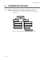
Outline of Operation, Setting, and Service Levels ........................................... 19
Operation Level ................................................................................................. 20
Setting Level ..................................................................................................... 21
Service Level ..................................................................................................... 22
Procedures for Setting Parameters .................................................................... 24
Lamp Replacement ............................................................................................ 27
Calibration ......................................................................................................... 28
5.2.1 Outline ....................................................................................................... 28
5.2.2 2-point Calibration Using Turbidity Standard Solutions .......................... 28
TROUBLESHOOTING ............................................................................................... 29
Revision Record .................................................................................................................... 1
IM 12E01A06-02E
3
Contents
4
IM 12E01A06-02E
1. OVERVIEW
1.
1.1
OVERVIEW
Features
The TB750G is a process turbidimeter employing the right angle light scattering method,
and has the following features.
• Highly reliable measurement with excellent linearity and repeatability
- Linearity: ±2% of reading or ±0.01 NTU, whichever is greater
- Repeatability: ±1% of reading or ±0.002 NTU, whichever is greater
- Display resolution: 0.001 NTU
• Easy-to-clean measurement cell
• Compact, lightweight converter and detector
• User configurable analog output range
- Analog output range: 0-0.2 NTU to 0-100 NTU
• Analog output range switching (2 or 3 ranges)
• Enhanced self-diagnostic function as standard
- Light source failure, input element failure, calibration failure, various circuit failures,
etc.
• Detector designed to remove influence of air bubbles
• A wide range of measurement conditions
- Low flow rate: 0.05 to 20 l/min {0.8 to 317 gal/h}
- High pressure: Up to 500 kPa {72 psi}
- Sample temperature: 0 to 50°C {32 to 122°F}
• Detector can be connected for in-line analysis
• 2 analog outputs, 3 relay contact outputs, and 1 serial communication
• Many options available upon request
• Ultrasonic transducer and oscillator for ultrasonic cleaning
• Various head tanks to accommodate application requirements
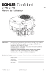
1.2
Measurement Principle
The measuring system of the TB750G turbidimeter, comprised of a detector and a
converter, complys with USEPA 180.1.
Scatted Light Detection Element
Scatted Light Detector
Receiver (Darkroom)
Light Source Lens
(Lamp)
Measuring
Water
Measurement Window (Glass)
F0101.EPS
Figure 1.1 Measurement Principle
IM 12E01A06-02E
5
2. PIPING AND WIRING
2.
2.1
PIPING AND WIRING
Piping
Piping methods depend on the application, select the appropriate system configuration,
and install pipes accordingly following examples.
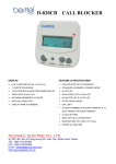
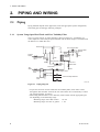
2.1.1
System Using Open Head Tank and Zero Turbidity Filter
This is a typical system. A piping diagram is shown in Figure 2.1. Air bubbles in a
water sample are removed by an open head tank and the water sample is introduced into
the detector at a stable flow rate.
Head Tank
H
Flow Control Valve
Sample Water
Effluent
Sample Water Drain
Valve
Valve
Drain
Tap
Water
Drain
TB750G
Detector
h
Sample Water
Outlet
Sample
Water
Drain
Sample Water Sample Water Drain Port
Inlet
Sample Water
Drain Valve
Supply Valve
Zero Water
Drain
Zero Water Supply Valve
Tap Water
Valve
Zero Water
Drain Valve
Zero Turbidity
Filter
Other Turbidity Detectors
F0320.EPS
Figure 2.1 Piping Diagram
• To prevent corrosion of water inside the zero turbidity filter, allow water to flow
through the filter and flow out from the zero water drain valve continuously at a flow
rate of approximately 10 ml/min.
• When using filtered water as zero reference, install a filter with the appropriate pore
size depending on the measuring range.
Measuring range of less than 2 NTU:
0.2 µm
Measuring range of 2 NTU or greater: 1 µm
6
IM 12E01A06-02E
2. PIPING AND WIRING
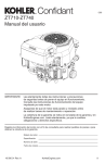
2.1.2
System without Head Tank and Zero Turbidity Filter
This is a simple system where a water sample is taken from the process and directly
introduced into the detector. This system configuration can be used when a water sample
contains a negligible amount of air bubbles or when the turbidity of a water sample is
high and the effect of air bubbles is nonsignificant.
CAUTION
Sample water conditions and ambient temperature must meet the specifications:
maximum pressure: 500 kPa; sample temperature: 0 to 50°C; ambient temperature: -5 to
50°C.
Flow Control Valve
Sample Water
Effluent
TB750G
Detector
Process Piping
Sample
Water
Sample Water
Sample Water
Valve
Tap Water
h
Sample Water
Outlet
Zero Water
Sample Water
Inlet
Sample Water
Supply Valve
Drain
Drain Port
Drain Valve
Drain
Zero Water Supply Valve
Tap Water
Valve
Zero Water
Drain Valve
Other Turbidity Detectors
Zero Turbidity
Filter
F0325.EPS
Figure 2.2 Piping Diagram
• The flow control should not be done on the inlet side of the detector.
• To prevent corrosion inside the zero turbidity filter, allow water to flow through the
filter and flow out from the zero water drain valve continuously at a flow rate of
approximately 10 ml/min.
IM 12E01A06-02E
7
2. PIPING AND WIRING
2.2
Wiring
2.2.1
Wiring Required for TB750G
TB750G Turbidity detector
TB750G Turbidity converter
L
CONVERTN POWER
ER
G
G
Power
supply *5
Grounding *1
(100V or less)
L
N TUS
G
Dedicated cable (1/2/3m)
SENSOR
Serial communication *3 *4
(RS-422)
U1U2
Grounding *1
(100V or less)
Power supply
cable
TUS400G Ultrasonic Oscillator *5
L2
L1
U1
U2
U3
S
S1
NO
NC
COM
Contact
output S1
S2
NO
NC
COM
Contact
output S2
FAIL
NO
NC
COM
Contact
output FAIL
A
B
C
COM
Range
contact output
G
Ultrasonic transducer
connecting cable
(maximum length: 15m)
(customer wiring)
Contact input
Analog output 1
(4-20mA DC) *3
Analog output 2
(4-20mA DC or
0-20mA DC) *3
RX+
RXTX+ RS-422
TXSG
G
IN1
INPUT
IN2
COM
RANGE
+ mA1
+ mA2 OUTPUT
G
Grounding *1
(100V or less)
Grounding *2
(100V or less)
(Note) Dotted wiring is external wiring. Use cable with 6 to 12 mm OD for wiring.
*1 Power terminal "G" on detector, detector case, and converter case must be grounded (ground resistance: 100V or less).
*2 External grounding terminal of ultrasonic oscillator must be grounded (ground resistance: 100V or less).
*3 Use 2-conductor shielded cable for analog output wiring and serial communication wiring.
*4 The wiring configuration is described below in case that RS-232C serial communication is selected.
Serial communication
(RS-232C)
*5
TXD
RXD RS-232C
SG
G
When option code "/US" is specified, TUS400G should be purchased separately.
When TUS400G is used in system, the power supply to TB750G should be the same as the supply voltage specified in
the MS Code of TUS400G.
F18.EPS
Figure 2.3 Connection Diagram
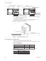
2.2.2
Wiring for Detector
Wire for connections to the following terminals:
(1) Power supply terminals;
(2) Power supply terminals for ultrasonic oscillator (when option code "/US" is
specified); and,
(3) External grounding terminal.
8
IM 12E01A06-02E
2. PIPING AND WIRING
Terminals TM3 (Power to Lamp)
(1) Power Supply Terminals
(2) Power Supply Terminals for
Ultrasonic Oscillator
Terminal G
(For Converter 2 Detector
Connecting Cable)
Connector for Converter 2 Detector Cable
F0310.EPS
Figure 2.4 Internal View of Detector
(3) External Grounding Terminal (M5 Screw)
(Norminal size of at least 2 mm2)
F0319.EPS
Figure 2.5 Grounding Terminal of Detector
2.2.3
Wiring for Converter
Wire for connections to the following terminals:
(1) Analog output/contact input terminals;
(2) Contact output/range contact output terminals;
(3) Serial communication terminals (when in use); and,
(4) Grounding terminal.
IM 12E01A06-02E
9
2. PIPING AND WIRING
(A) Converter 2 Detector
Connecting Cable
Front Cover
Serial Communication
Terminals
Connector for
Converter 2 Detector Cable
(3) Serial Communication
Front Cover
Terminals
Terminal Cover
(2) Contact Output/
Range Contact
Output Terminals
(B)
Terminal G
(For Converter 2
Detector Connecting Cable)
Analog Output/Contact Input Terminals
(1) Analog Output/Contact Input Terminals
F0309.EPS
How to Remove the Terminal Cover
Disconnect the converter-detector connecting cable (A) and its grounding wire (B) from the converter.
Remove the terminal cover by sliding it slightly to the left and pulling it forward.
Figure 2.6 Internal View of Converter
Toothed Lock Washer
Grounding Wire
(Nominal Size of at least 2 mm2)
(4) Grounding Terminal (M4 Screw)
F0318.EPS
Figure 2.7 Grounding Terminal of Converter
Contact Output (S1, S2 and FAIL) Wiring
• Be sure to use the contacts meeting the conditions below.
• Functions of contact outputs S1 and S2 should be set in Codes 40 and 41 at service
level. Refer to section 4.3.
Table 2.1 Contact Rating
AC
Contact maximum permissible voltage
Contact maximum permissible current
Contact maximum permissible power
(resistance load)
DC
30 V
3A
60 W
250 V
2A
125 VA
T0303.EPS
Table 2.2 Contact Operation
Status
In action
Not in action
Power OFF
Contact S1, S2
LED NO
NC
ON Closed Open
OFF Open Closed
OFF Open Closed
Contact FAIL
LED NO
NC
ON Open Closed
OFF Closed Open
OFF Open Closed
T01.EPS
10
IM 12E01A06-02E
3. OPERATION
3.
OPERATION
3.1
Preparation
3.1.1
Outline
1. Installation Check
• Make sure that TB750G converter and detector
are fixed fimly.
• Unused cable inlets should be plugged to
prevent moisture from entering.
2. Piping Check
3. Wiring Check
4. Supplying Power
• Note that the TB750G does not have an internal
power switch.
5. Warm-up
• Upon power up, allow the meter to warm up for
at least one hour.
• When using zero turbidity filter, allow water to
run through it for at least one hour.
6. Setting and Checking Parameters
• For details of parameter settings, refer to
chapter 4.
7. Calibration
• For details of calibrations, refer to the following
pages.
8. Supplying a Water Sample and
adjusting the flow rate
9. Operation check
• Adjust the opening of the valve at the sample
water out of the detector.
• Make sure that the system is free of defects.
F3.1.EPS
IM 12E01A06-02E
11
3. OPERATION
3.1.2
Converter Operation Panel
HOLD
TEMP. MAN
UNIT
FAIL
YES NO
ENT
YES
NO
FNU
NTU mg/l
MODE
SET UP
MEASURE
CAL
CAL START
WASH START
DISPLAY
HOLD
SETPOINTS
RANGE
SET HOLD
CAL / WASH
SERVICE
MODE
Turbidity Unit Indication
Operation Key
CONTACTS
([*]: To enter the operation level
from measurement mode)
S1
S2
ENT
FAIL
Contact Status LED
LCD Screen
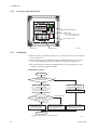
3.1.3
Operation Key
F0504.EPS
Calibration
(1) When performing a calibration using 0.2 or 1.0 µm filtered water as zero reference,
refer to section 3.1.4.
(2) When performing a 2-point calibration using standard solutions, refer to section
3.1.5. Use this method to perform a calibration complying with EPA 180.1.
Note: The instrument has been pre-calibrated using 0.2 µm filtered water as zero
reference at the factory before shipment.
Calibration Flow Chart
Start calibration
NO
Is filtered water used
as zero reference?
YES
Perform span/zero calibration
using filtered water
Perform 2-point calibration
using standard solutions*
Perform zero calibration
Perform point calibration
first using zero solution
Is span calibration performed
using check block or
standard solution?
Standard Solution
Check block
Perform span calibration
using check block.
Refer to Section 3.1.4.
Perform span calibration
using standard solution.
Refer to Section 3.1.4.
Perform second point
calibration using span solution.
Refer to Section 3.1.5.
End calibration
* Calibration complying with EPA Method 180.1.
12
F3.2.EPS
IM 12E01A06-02E
3. OPERATION
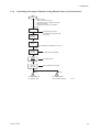
3.1.4
Performing Zero/span Calibration Using Filtered Water as Zero Reference
START
•
•
•
•
•
Supply power
Warm-up (at least 1 hour)
Allow water to run through the zero filter
Supply zero water
Prepare span solution, if necessary
[MODE]
CALB
[YES]
X.XXX
STD.CAL
Automatically goes into
maintenance mode and holds
the output.
[YES]
X.XXX
ZERO
• Confirm reading has stabilized (3 to 5 min)
[YES]
0.000
VALUE
{0.000} None configurable
[ENT]
X.XXX
ZERO
X.XXX
CAL.END
Auto-adjustment
Zero calibration is complete
[NO]
A
To span calibration
using check block
IM 12E01A06-02E
[YES]
B
To span calibration
using standard solution
F3.3.EPS
13
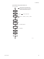
3. OPERATION
Span calibration using check block
Note: For span calibration using standard solution, refer to next page.
From zero calibration
A
X.XXX
STD.CAL
[YES]
X.XXX
ZERO
[NO]
X.XXX
SPAN
• Stop supplying zero water
• Drain zero water
• Install check block *
• Supply zero water
• Confirm reading has stabilized (3-5 min)
[YES]
XX.XX
VALUE
{XX.XX} None configurable
• Check that display reads the value of check block
[ENT]
XX.XX
SPAN
XX.XX
CAL.END
Auto-adjustment
Span calibration is complete
[YES]
HOLD
Release HOLD **
[NO]
END
* How to install check block
1. Remove the rubber cover from the top of the detector.
2. Remove the retaining plate on the window of the top cover
by loosening the 2 setscrews.
3. Detach the observation window and replace it with the
check block. Fix it with the 2 setscrews securely.
Check block
** Be sure to release HOLD
14
F3.4.EPS
IM 12E01A06-02E
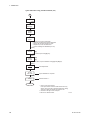
3. OPERATION
Span calibration using standard solution (1/2)
From zero calibration
Before performing span calibration using
standard solution, standard solution/check
block selection should be set to "0 (standard
solution)" in CODE 16 as shown below.
B
HOLD
[YES]
HOLD
[*] at least second
To enter operation level
*SETP
[NO]
[NO]
[NO]
(3 times)
{*SETP} -> {*RANGE} -> {*HOLD} -> {*SERV}
*SERV
[YES]
16
*CODE
[m]
[c]
• Enter "16" using [m]and [c] keys
[YES]
0
*CAL.TP
[m]
• Enter "0" using [m] key
[ENT]
*SERV
[MODE]
HOLD
[YES]
HOLD
[MODE]
C
F3.5.EPS
IM 12E01A06-02E
15
3. OPERATION
Span calibration using standard solution (2/2)
C
CALB
[YES]
X.XXX
STD.CAL
[YES]
X.XXX
ZERO
[NO]
X.XXX
SPAN
• Remove top cover (6 setscrews)
• Rinse the cell with span solution and drain
• Fill the cell with span solution to 90% *
• Replace top cover with setscrews
• Confirm reading has stabilized (3-5 min)
[YES]
00.00
VALUE
[c]
• Set decimal point using [c] key
[ENT]
20.00 **
VALUE
[m]
[c]
• Enter value of span calibration using [m] and [c] keys
[ENT]
XX.XX
SPAN
XX.XX
CAL.END
Auto-adjustment
Span calibration is complete
[YES]
HOLD
Release HOLD ***
[NO]
END
* How to pour span solution
Pour span solution into the measurement cell very
slowly, using a funnel or relevant equipment, taking
care not to allow air bubbles to enter the cell.
** Number in the figure is an example.
*** Be sure to release HOLD
F3.6.EPS
16
IM 12E01A06-02E
3. OPERATION
3.1.5
Performing 2-point Calibration Using Standard Solution
START
• Supply power
• Warm-up (at least 1 hour)
• Wash the cell
• Prepare zero and span solutions
[MODE]
CALB
[YES]
X.XXX
STD.CAL
[NO]
X.XXX
SMP.CAL
[YES]
X.XXX
ZRSPAN
•
•
•
•
•
Remove top cover (6 setscrews)
Rinse the cell with zero solution and drain
Fill the cell with zero solution to 90% *
Replace top cover with screws
Confirm reading has stabilized (3-5 min)
[YES]
0.000
VALUE.Z
[c]
• Set decimal point using [c] key
[ENT]
0.020 **
VALUE.Z
[m]
[c]
• Enter value of zero calibration using [m] and [c] keys
[ENT]
X.XXX
ZERO
Auto-adjustment
X.XXX
SPAN
• Remove top cover (6 setscrews)
• Rinse the cell with zero solution and drain
• Fill the cell with zero solution to 90% *
• Replace top cover with screws
• Confirm reading has stabilized (3-5 min)
[YES]
00.00
VALUE.S
[c]
• Set decimal point using [c] key
[ENT]
20.00 **
VALUE.S
[m]
[c]
• Enter value of span calibration using [m] and [c] keys
[ENT]
XX.XX
SPAN
XX.XX
CAL.END
Auto-adjustment
Span calibration is complete
[YES]
HOLD
Release HOLD ***
[NO]
END
IM 12E01A06-02E
* How to pour zero solution
Pour a span solution into the measurement cell very
slowly, using a funnel or relevant equipment, taking
care not to allow air bubbles to enter the cell.
** Numbers in the figures are examples.
*** Be sure to release HOLD
F3.7.EPS
17
3. OPERATION
3.2
Normal Operation
The TB750G turbidimeter does not normally require any manual operations except when
periodic cleaning/calibration is performed or when a failure occurs.
3.2.1
When Sample Water Supply is Cut Off
The turbidity measurement is not affected by temporary suspension of sample water
supply, but long-term suspension may interfere with the accuracy of the instrument.
Since the TB750G cannot detect whether the sample water supply is stopped or not,
periodical check of the sample line is needed.
3.2.2
Shutdown
The parameter settings and other information set in the turbidimeter are retained even if
power is turned off. If the instrument will be out of operation for a long period, power
should be removed. Dirt and/or stains on the instrument should be washed off
thoroughly when the turbidimeter is to be removed from the site. Rinse the inside of the
measurement cell, and then empty the cell or keep zero water running through the cell.
3.2.3
Restart
When power is returned, the turbidimeter is put into the measurement state. It requires at
least one hour for warm-up. Check that the reading stabilizes well, before performing
calibration.
18
IM 12E01A06-02E
4. PARAMETER SETTING
4.
4.1
PARAMETER SETTING
Outline of Operation, Setting, and Service Levels
Parameters should be set in the relevant mode classified into three levels: operation,
setting and service.
Measurement Mode
[MODE] key
Operation Level
[ * ] For at least second
Setting Level
CALIB (Calibration)
STEP (Alarm setting)
DISP (Message display)
RANGE (Analog output)
STEP (Alarm setting)
HOLD (Hold selection)
HOLD (Hold selection)
Service Level
CODE XX
F0501.EPS
Figure 4.1 Transition between Measurement Mode and Three Levels
IM 12E01A06-02E
19
4. PARAMETER SETTING
4.2
Operation Level
This is the level where, basically, operations regarding routine inspections and
maintenance, such as calibration and manual cleaning, can be done. Also, the desired
display item on the message display can be selected at this operation level.
Measurement
mode
[MODE]
CALIB
[YES]
[YES]
HOLD
Calibration mode
[NO]
DISP
[YES]
[YES]
Message display selection mode
[NO]
*1
SETP
[YES]
[YES]
[NO]
*2
HOLD
HOLD
Alarm setting mode
*3
[YES]
[YES]
Hold selection mode
[NO]
*1: Skipped if alarm setting function is set to “0: Disabled” in Code 51 at service level, or unless
either of functions of contact output S1 or S2 is set to “1: Alarm” in Code 40 or 41 at service
level.
*2: Skipped if hold function is set to “*H.OFF: Disabled” in SET HOLD mode at setting level.
*3: If [YES] key is pressed, analog output is held in measurement mode.
F0601.EPS
Table 4.1 Setting Parameters at Operation Level
Mode
CAL
Setting Parameter
Calibration
Using turbidity standards, or
using water sample
Start
Turbidity value
Self-adjustment in process
End
Display
CALIB
ZERO or SPAN
or ZRSPN
VALUE
0.001 to 2000[NTU]
*1
ZERO or SPAN
CAL.END
Not available
WASH START
Not available
Message display selection
DISP
Analog output 1 current
XX.XmA1
Analog output 2 current
XX.XmA2
Switchable output range state
(No pointer at
Alarm setting
mode display)
High alarm setpoint
Low alarm setpoint
HOLD
Default
STD.CAL or
SMP.CAL
CAL START
DISPLAY
Setting Range
Hold selection
Output 1 current
RNG1/2-A/B/C
*2
* SETP
* S.TB-H
* S.TB-L
HOLD
*3
–010.0 to 2200.0[NTU]
*1
2200.0(NTU)
–010.0 to 2200.0[NTU]
*1
-010.0(NTU)
*4
Hold selection
(Disabled)
*1: Although setting range is up to 2000 NTU, measuring range is up to 100 NTU.
*2: Skipped if analog output range switching selection {*RNGPR} is set to “0: Fixed” in CODE 30 at service level.
*3: Skipped if alarm setting function is set to “0: Disabled” in Code 51 at service level, or if either function of contact
output S1 or S2 is not set to “1: Alarm” in Code 40 or 41 at service level.
*4: Skipped if hold function is set to “*H.OFF: Disabled” in SET HOLD mode at setting level.
T0501.EPS
20
IM 12E01A06-02E
4. PARAMETER SETTING
4.3
Setting Level
There are modes where parameters regarding output signals and contact outputs can be
set.
*2
Measurement
mode
HOLD
[ * ] For at least second
*1
*SETP
[YES]
SETPOINTS Mode
[NO]
*RANGE
[YES]
RANGE Mode
[NO]
*HOLD
[NO]
*SERV
[YES]
SET HOLD Mode
*3
[YES]
Service Level
[NO]
*1: Skipped unless either of functions of contact output S1 or S2 is set to “1: Alarm” in
Code 40 or 41 at service level.
*2: Skipped if hold function is set to “*H.OFF: Disabled” in SET HOLD mode at setting
level.
*3: For service level, see Section 4.4.
F0605.EPS
Table 4.2 Setting Parameters at Setting Level
Mode
SETPOINTS
Setting Parameter
Alarm setting
High alarm setpoint
Low alarm setpoint
RANGE
Analog output range setting
Fixed range for output 1, or
fixed range for output 2
Zero point
Span point
Local range selection
Local range for output 1, or
local range for output 2
SET HOLD
Display
* SETP
S.TB-H
*
* S.TB-L
* RANGE
* ZERO
* SPAN
*LCL.1 or
*LCL.2
Hold function enabled, or
* H.ON or
* H.OFF
fixed value
Fixed value for output 1
Fixed value for output 2
*1
–010.0 to 2200.0[NTU]
*1
2200.0(NTU)
–010.0 to 2200.0[NTU]
*1
-010.0(NTU)
0000.00 to 2000.00[NTU]
0000.00(NTU)
0000.00 to 2000.00[NTU]
0100.00(NTU)
* LOCAL
* HOLD
Last measured value, or
Default
* FIXR.1 or
*FIXR.2
Hold parameter setting
hold function disabled
Setting Range
* H.LST or
* H.FIX
* H.mA1
* H.mA2
0: Range A, 1: Range B, 2: Range C
* H.ON (Enabled)
0:Range A
* H.ON:Enabled
* H.OFF (Disabled)
* H.LST (Last measured value)
* H.LST:Last
* H.FIX (Fixed value)
measured value
02.0 to 22.0[mA]
22.0(mA)
00.0 to 22.0[mA](0-20mA)
22.0(mA)
02.0 to 22.0[mA](4-20mA)
CAL/WASH
SERVICE
Not available
*2
*1: Skipped if alarm setting function is set to "0: Disabled" in Code 51 at service level, or if either function of contact
output S1 or S2 is not set to "1: alarm" in Code 40 or 41 at service level.
*2: For service level, see Section 4.4.
IM 12E01A06-02E
T0502.EPS
21
4. PARAMETER SETTING
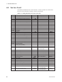
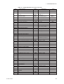
4.4
Service Level
The TB750G turbidimeter has various functions. At this level there are modes where
functions can be selected according to need for the operation.
Table 4.3 Setting Parameters at Service Level (1/2)
Code
Setting Parameter
Display
Setting Range
Default
CODE02 Input voltage display
Transmitted light detection element input display
Scattered light detection element input display
End
* IN1
* IN2
* END
CODE08 Spike detection parameter setting
Spike detection function enabled or disabled
Limit value
Hold time
Sampling time
0:Disabled
* SPIKE
* LIMIT
0: Disabled, 1: Enabled
* HLD-T
* SMP-T
005 to 600[s]
030(s)
001 to 600[s]
030(s)
000.000 to 999.999
999.999(NTU)
CODE11 Zero calibration factor display
Zero calibration factor display
Depends on MS Code
*CAL.A
CODE12 Slope display
Slope display
100.0(%)
* SL
CODE13 Zero correction factor setting
Zero correction factor setting
*CAL.B
–9.000 to 09.000[NTU]
*CAL.K
0.2500 to 4.0000
00.000(NTU)
CODE14 Sensitivity correction factor setting
Sensitivity correction factor setting
1.0000
CODE16 Standard solution/check block selection
Standard solution or check block
*CAL.TP
0: Standard Solution, 1: Check Block
1:Check Block
CODE17 Check block turbidity setting
Check block turbidity
*PLATE
0.001 to 2000[NTU]
CODE30 Analog output range
switching parameter setting
Range switching function selection
* RNGPR
*RSET
Range A setting
* RSET.A
Range switching output selection
0: Fixed, 1: AO1, 2: AO2
0: Local, 1: Automatic, 2: Remote
0:Fixed
1:Automatic
2RNG, 3: Remote 3RNG
Zero point for range A
Span point for range A
Range B setting
Zero point for range B
Span point for range B
Range C setting
Zero point for range C
Span point for range C
Automatic range switching point
0000.00 to 2000.00[NTU]
0000.00(NTU)
0000.00 to 2000.00[NTU]
0010.00(NTU)
*ZERO
0000.00 to 2000.00[NTU]
0000.00(NTU)
* SPAN
0000.00 to 2000.00[NTU]
0100.00(NTU)
* RSET.C
* ZERO
0000.00 to 2000.00[NTU]
0000.00(NTU)
0000.00 to 2000.00[NTU]
1000.00(NTU)
* ZERO
*SPAN
* RSET.B
* SPAN
*AUTOR
070 to 100[%]
080(%)
CODE33 Analog output 2 range selection
Range selection for output 2
Fixed value for hold
*mA2
*H.mA2
0: 4.0-20.0mA, 1: 0.0-20.0mA
00.0 to 22.0[mA](0-20mA)
0:4.0-20.0mA
22.0(mA)
02.0 to 22.0[mA](4-20mA)
Fixed value for hold during failure
*FH.mA2
00.0 to 22.0[mA](0-20mA)
22.0(mA)
02.0 to 22.0[mA](4-20mA)
T0503_1.EPS
22
IM 12E01A06-02E
4. PARAMETER SETTING
Table 4.3 Setting Parameters at Service Level (2/2)
Code
Setting Parameter
Display
Setting Range
Default
CODE35 Hold during failure parameter setting
Hold function enabled or disabled
Last measured value, or
fixed value
* FHOLD
*FH.LST /
*FH.FIX
0: Disabled, 1: Enabled
* FH.LST(Last measured value)
1: Enabled
*FH.FIX:Fixed value
* FH.FIX(Fixed value)
Fixed value for output 1
*FH.mA1
02.0 to 22.0[mA]
22.0(mA)
Fixed value for output 2
*FH.mA2
00.0 to 22.0[mA](0-20mA)
22.0(mA)
02.0 to 22.0[mA](4-20mA)
CODE37 Time constant setting
Time constant in measurement
*TC
000 to 120[s]
020(s)
Time constant in maintenance
*TC-M
000 to 120[s]
006(s)
CODE40 Contact output S1 function selection
Function of contact output S1
* S1
0:None , 1: Alarm, 2: Automatic
calibration/washing, 3: Maintenance
1: Alarm
* S2
0:None , 1: Alarm, 2: Automatic
calibration/washing, 3: Maintenance
3: Maintenance
CODE41 Contact output S2 function selection
Function of contact output S2
CODE44 Delay time/hysteresis setting
Delay time
Hysteresis
* D.TIME
* HYST
000 to 199[s]
000(s)
000 to 100[%]
002(%)
CODE50 Auto return function selection
Auto return function enabled or disabled
*RET
0: Disabled, 1: Enabled
0: Disabled
* MODE
0: Disabled, 1: Enabled
0: Disabled
CODE51 Alarm setting function selection
Alarm setting function enabled or disabled
CODE52 Password setting
Password
*PASS
0:No password, 1:111, 2:333, 3:777,
4:888, 5:123, 6:957, 7:331, 8:546, 9:847
0.0.0
CODE54 Negative nondisplay/nonoutput selection
Negative nondisplay/nonoutput enabled or disabled
*MINUS
0: Disabled, 1: Enabled
0.0: Disabled.Disabled
0: NTU, 1: FNU, 2: mg/l
0: NTU
CODE61 Turbidity unit selection
Turbidity unit
*UNIT
CODE64 Software version display
Software version display
1.00
*VER
CODE66 Error “E2xx” error level selection
Error levels of errors “E201” to “E206”
*201-6
0: Disable, 1: Level 1, 2: Level 2
1.1.2.2.2.2
*301-6
0: Disabled, 1: Enabled
1.1.1.1.1.1
*307
0: Disabled, 1: Enabled
1
*311-6
0: Disabled, 1: Enabled
1.1.1.1.1.1
*317
0: Disabled, 1: Enabled
1
CODE67 Error “E3xx” error detection selection
Error detection for “E301” to “E306”
Error detection for “E307”
Error detection for “E311” to “E316”
Error detection for “E317”
CODE71 Analog output test
Start test for output 1
*AO1.T
Test current flowing
End
Start test for output 2
*END
*AO2.T
Test current flowing
End
*END
CODE72 Contact output test
Test 1
*DO.T1
0: Non-action, 1: Action
Last measured value held
Test 2
*DO.T2
0: Non-action, 1: Action
Last measured value held
CODE73 Contact input test
Test
*DI.T
CODE79 Initialization
Start
*LOAD
Default loading
*WAIT
T0503_2.EPS
IM 12E01A06-02E
23
4. PARAMETER SETTING
4.5
Procedures for Setting Parameters
An example for setting parameters, the procedures are described in following modes. For
more detail on the other functions, refer to User's Manual IM 12E01A06-01E Section 6.
(1)
(2)
(3)
CAL Mode: {CALIB}
HOLD Mode: {HOLD}
RANGE Mode: {*RANGE}
(1) CAL Mode: {CALIB}
CALIB
[YES]
X.XXX
[NO]
X.XXX
STD.CAL
*1 [YES]
SMP.CAL
[YES]
*2
X.XXX
[NO]
X.XXX
ZERO
[NO]
SPAN
[YES]
*3
[NO]
[YES]
0.000
0.000
VALUE
[ENT]
*5
[c]
[m]
[ENT]
X.XXX
X.XXX
ZERO
SPAN
[NO]
ZRSPN
*4 *5
VALUE
X.XXX
X.XXX
VALUE.Z
SPAN
[YES]
[c]
[m]
[YES]
*5
*5
0.000
VALUE
[ENT]
[c]
[m]
[ENT]
X.XXX
ZERO
Self-adjustment
or [ENT]
*6
[NO]
X.XXX
ZERO
[YES]
0.000
[NO]
0.000
[c]
[m]
VALUE
[ENT]
X.XXX
X.XXX
ZERO
SPAN
X.XXX
SPAN
*5
[YES] *7
0.000
VALUE.S
[c]
[m]
[ENT]
X.XXX
Self-adjustment
or [ENT]
*6
[NO]
X.XXX
SPAN
Self-adjustment
or [ENT]
*6
Self-adjustment
or [ENT]
*6
Self-adjustment
or [ENT]
*6
Self-adjustment
or [ENT]
*6
CAL.END
*7
[YES]
HOLD
Measurement
mode
*1: During the time between [YES] key press on {STD.CAL} display and [YES] or [NO] key press on
{CAL.END} display or on error code display or [MODE] key press to abort, data display shows turbidity
based on sensitivity correction factor (K)=1 and zero correction factor (B)=0. (Value not affected by
SMP.CAL: Display by T1={(S0/(SL/100)}*(V-A), not by T2=K(T1+B))
*2: Span calibration in {STD.CAL} is performed using turbidity standards or check block that has been
selected in CODE16.
*3: In zero calibration, calibration value should be “0.000” and cannot be changed. Only [ENT] key is
accepted to confirm.
*4: In span calibration using check block, calibration value cannot be changed. Only [ENT] key is accepted
to confirm.
*5: First determine the decimal point using [>] key and then set value in the range of 0.000 to 20000 NTU.
*6: Pressing [ENT] key during self-adjustment will abort the procedure, and the turbidity when [ENT] key is
pressed will be used for calibration factor calculation.
*7: Only [YES] key is accepted to confirm.
Note:Calibration factor will be updated when the calibration procedure is completed without cancellation or
errors. If [YES]/[NO] key is pressed on error code display, the instrument goes to {CALIB} display.
Error E203 or E204 appears after the instrument once returns to measurement display.
F0602.EPS
Figure 4.2 CAL Mode Flow Chart
24
IM 12E01A06-02E
4. PARAMETER SETTING
(2) HOLD Mode: {HOLD}
In this mode whether the analog output is held or not in measurement mode, can be
selected. This function is available when the hold function is set to “1: Enabled” in SET
HOLD mode at the setting level. If the function is set to “0: Disabled,” this mode will
be skipped.
HOLD
[YES]
HOLD
[NO]
(Flashing)
[YES]
Hold disabled in
measurement mode
Hold enabled in
measurement mode
HOLD status indicator turns on.
Measurement
mode
F0604.EPS
Figure 4.3 HOLD Mode Flow Chart
If the hold function has been set to “1: Enabled” in SET HOLD mode at the setting
level, the instrument automatically goes into this HOLD mode when it returns from any
level to measurement mode, with the exception of DISPLAY mode.
IM 12E01A06-02E
25
4. PARAMETER SETTING
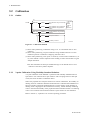
(3) RANGE Mode: {*RANGE}
In this mode, an output range corresponding to analog output 1 and 2 can be set. Enter
turbidity values corresponding to a 4 mA (or 0 mA) output signal (zero point) and a 20
mA output signal (span point).
*RANGE
[YES]
*1
*FIXR.1
[NO]
*2
*FIXR.2
[YES]
[NO]
*3
*LOCAL
[NO]
[YES]
[YES]
*4
XXXX.XX
*ZERO
[c]
[m]
XXXX.XX
*ZERO
[YES]
[c]
[m]
X
[m]
Local range for output 1
X: 0(Range A), 1(Range B)
or 2(Range C)
[m]
Local range for output 2
X: 0(Range A), 1(Range B)
or 2(Range C)
*LCL.1
[YES]
[YES]
*5
XXXX.XX
*SPAN
*6
[ENT]
[c]
[m]
XXXX.XX
*SPAN
*6
[c]
[m]
X
*LCL.2
[ENT]
[ENT]
*1: Skipped if analog output range switching selection {*RNGPR} is set to “1: Analog output 1” in
CODE 30 at service level.
*2: Skipped if analog output range switching selection {*RNGPR} is set to “2: Analog output 2” in
CODE 30 at service level.
*3: Displayed only if analog output range switching selection {*RNGPR} is set to “1: Analog output 1”
or “2: Analog output 2” and range switching function selection {*RSET} is set to “0: Manual” in
CODE 30 at service level.
*4: Displayed only if analog output range switching selection {*RNGPR} is set to “1: Analog output 1”
in CODE 30 at service level.
*5: Displayed only if analog output range switching selection {*RNGPR} is set to “2: Analog output 2”
in CODE 30 at service level.
*6: Zero and span points should be set together. Only after span point has been entered, both zero and
span points are accepted. Cancellation by pressing [MODE] key during the procedure will not
change either of the points.
F0607.EPS
Figure 4.4 RANGE Mode Flow Chart
26
IM 12E01A06-02E
5. MAINTENANCE
5.
5.1
MAINTENANCE
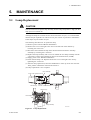
Lamp Replacement
CAUTION
Wait for some time to replace lamp assembly because lamp temperature is high just after
lamp power was turned off.
Although the lamp has a normal service life of more than one year, it is recommended
that the lamp be replaced at an interval of one year in terms of preventive maintenance.
Some lamps may fail within one year.
The following describes how to replace the lamp.
(1) Remove power from the TB750G turbidimeter.
(2) Remove the cover of the light source unit on the left side of the detector by
loosening the 4 setscrews.
(3) Disconnect the terminals for lamp from the terminal block. Remove the lamp
assembly by loosening the 2 setscrews.
(4) Replace the lamp assembly with a new one. Mount the new lamp assembly with the
2 setscrews. Connect the terminals for lamp to the terminal block (LAMP).
(5) Supply power to the TB750G turbidimeter.
(6) Check that the lamp is lit. Replace and fix the cover of the light source unit by
tightening the 4 setscrews.
(7) After the lamp replacement, allow the turbidimeter to warm up for at least one hour.
Then, perform calibrations instructed in Sections 3.
(8) Lamp replacement is now complete.
Lamp Assembly
Cover of the Light Source Unit
A
Cover for
Setscrews (2) Terminal
Terminal Block
Setscrews (2)
Terminal Block
Lamp Assembly
[View A]
F0704.EPS
Figure 5.1 Lamp Replacement
IM 12E01A06-02E
27
5. MAINTENANCE
5.2
Calibration
5.2.1
Outline
(1)
CALIB
STD.CAL
SMP.CAL
ZERO
Zero calibration using zero turbidity
water
SPAN
Span calibration using check block
Span calibration using standard
solution
ZRSPN
2-point calibration using standard
solutions
ZERO
Zero point correction
SPAN
Sensitivity correction
(2)
(3)
Calibration
using
filtered
water as
zero
reference
F0705.EPS
Figure 5.2 Calibration Methods
(1) Select when performing a calibration using 0.2 or 1.0 µm filtered water as zero
reference.
(2) Select when performing a 2-point calibration using standard solutions. Use this
method to perform a calibration complying with EPA 180.1.
(3) Select when performing a zero point or sensitivity correction after calibration (1) or
(2). This method is used to adjust the meter reading to reflect the lab data in a grab
sample calibration.
Note: The instrument has been pre-calibrated using 0.2 µm filtered water as zero
reference at the factory before shipment.
5.2.2
2-point Calibration Using Turbidity Standard Solutions
A 2-point calibration of the TB750G is performed with turbidity standard solutions
equivalent to zero solution and to span solution. After accepting both zero and span
values, the meter calculates a calibration factor.
When user-prepared zero and span solutions are used for calibrations, the turbidity of
diluting water for calibration should be measured with a calibrated lab turbidimeter in
advance. Prepare a formazin standard solution as a span solution. If the turbidity of
diluting water is high against the measurement accuracy, add the turbidity of diluting
water to the nominal turbidity of the prepared formazin standard solution. Use diluting
water as zero solution and a formazin solution as span solution for the calibration.
Refer to Section 3, “Operation” for concrete operating procedures.
28
IM 12E01A06-02E
6. TROUBLESHOOTING
6.
TROUBLESHOOTING
Table 6.1 Error Code List (1/2)
No.
Error
E101 Flash memory
failure
E102 EEPROM write
failure
E103 RAM failure
E104 AD converter
failure
E201 Input voltage
failure
E202 Disconnection or
detection element
failure
E203 Lamp life expired
E204 Lamp intensity
failure
E205 Calibration failure
Occurrence
Problem
Return
When power is turned SUM results of flash memory do not match
on.
programmed SUM values 5 consecutive times.
All modes
Data is written in EEPROM and verified, and
write failure occurs 3 consecutive times.
When power is turned RAM area failure (3 consecutive times).
on.
All modes
AD converter failure (3 consecutive times).
When power is turned off
and then on again, and
problem is eliminated.
(Without [YES]/[NO] key
press.)
Either IN1 or IN2 input voltage is outside the
range of -0.15 to 1.2 V (fixed), including
abnormal value 0x7FFF or 8000, for 5
consecutive seconds.
Either IN1 or IN2 input voltage is less than PD
check voltage for 5 consecutive seconds.
When problem is
eliminated for 5
consecutive seconds.
When [YES]/[NO] key is
pressed, error code
display disappears, at the
same time during failure,
error is once removed.
All modes
All modes
Zero calibration
coefficient A rewriting
timing. (excluding
when E301 or E311
occurs.)*1
E301 to E307, E311
to E317, E321 during
PC communication
occurrence timing
During zero calibration self-adjustment, input
voltage IN1 is less than lamp life check voltage
for 5 consecutive seconds. (Not detected when
E301 is occurring.) Rewriting of zero calibration
coefficient A is performed.
Any of E301 to E307, E321 during PC
communication is occurring.
When problem is
eliminated. When
[YES]/[NO] key is
pressed, error code
display disappears, at the
same time during failure,
error is once removed.
T0804-1.EPS
IM 12E01A06-02E
29
6. TROUBLESHOOTING
Table 6.1 Error Code List (2/2)
No.
Error
E301 Turbidity zero
calibration
coefficient A
failure
Occurrence
Problem
During zero
calibration (zero
water).
Turbidity zero calibration coefficient A newly
determined after zero calibration (zero water or
lamp OFF) is outside of the range of 0 to 5, or each
coordinate value of newly determined linearized
table is outside of the range of -99999 to 999999.
E302 Turbidity slope During span
Turbidity slope value SL newly determined after
SL failure
calibration (standard span calibration (standard solution) is outside of the
solution)
range of 25 to 200%, or each coordinate value of
newly determined linearized table is outside of the
range of -99999 to 999999.
E303 Turbidity check During span
Turbidity slope value SL newly determined after
block failure
calibration (check
span calibration (check block) is outside of the
block)
range of 50 to 150%, or each coordinate value of
newly determined linearized table is outside of the
range of -99999 to 999999.
E304 Turbidity zero
During zero shift
Turbidity zero correction factor B newly determined
correction
calibration
after zero shift calibration is outside of the range of
factor B failure
-9 to 9.
E305 Turbidity
During span
Turbidity sensitivity correction factor K newly
sensitivity
calibration
determined after span calibration (sensitivity
correction
(sensitivity
correction) is outside of the range of 0.25 to 4.
factor K failure correction)
E306 Turbidity
During turbidity
Turbidity reference sensitivity SO newly set after
reference
reference sensitivity span calibration (check block) is outside of the
sensitivity SO calibration
tolerance of 0.0001 to 2000, or each coordinate
failure
value of newly determined linearized table is outside
of the range of -99999 to 999999.
E307 Turbidity
All calibrations
Turbidity self-adjustment is not complete before selfresponse time
adjustment time has elapsed.
failure
E321 Communication During
Any communication error during communication
error
communication with with PC.
PC
E351 Analog output
range setting
failure
During parameter
setting in RANGE
mode or CODE 30.
E352 Parameter
setting failure
During parameter
setting
Either of:
(1) Zero point ≥ span point, or
(2) Span point - zero point < 20% of span point or
0.20, whichever is greater (for turbidity) or ( span
point - zero point < 5.00 (for color).
When automatic range is selected in CODE 30, also
possible:
(3) At each span point, Range A ≥ Range B, or
(4) at each span point, Range B ≥ Range C
Value outside the setting range is set in setting
other than AO range setting.
Return
When problem is
eliminated. When
[YES]/[NO] key is pressed,
error code display
disappears, at the same
time during failure, error is
once removed.
When problem is
eliminated in the next
communication (only one
time is OK). When
[YES]/[NO] key is pressed,
error code display
disappears, at the same
time during failure, error is
once removed. (excluding
RS signal during
communication with
calibration/cleaning
controller.)
When [YES]/[NO] key is
pressed, error code
display disappears and
error is removed.
T0804-2.EPS
Refer to the user's manual IM 12E01A06-01E for details.
30
IM 12E01A06-02E
Revision Record
Manual Title : Model TB750G Right Angle Scattered Light Turbidimeter Quick Start Manual
Manual Number : IM 12E01A06-02E
Edition
Date
Remark (s)
1st
Apr. 2006
Newly published


![SS400G MLSS Converter [Style:S2.2]](http://vs1.manualzilla.com/store/data/005726371_1-b873ef07ceb169a0226d293b313a67fd-150x150.png)