1
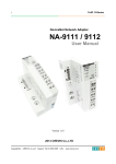
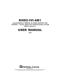
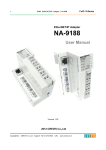
Programmable I/O (PIO) NA-9379, Communication KI00342 2014-10 1 Function and area of use The Programmable I/O (PIO) combines CODESYS control with the opportunity to build control systems to the exact size and specifications for the I/O signals involved. In this document “PIO” are used for “Programmable I/O” (NA-9379). 2 About this Start Up document Copyright © Beijer Electronics, 2014 This documentation (below referred to as ‘the material’) is the property of Beijer Electronics. The holder or user has a non-exclusive right to use the material. The holder is not allowed to distribute the material to anyone outside his/her organization except in cases where the material is part of a system that is supplied by the holder to his/her customer. The material may only be used with products or software supplied by Beijer Electronics. Beijer Electronics assumes no responsibility for any defects in the material, or for any consequences that might arise from the use of the material. It is the responsibility of the holder to ensure that any systems, for whatever applications, which is based on or includes the material (whether in its entirety or in parts), meets the expected properties or functional requirements. Beijer Electronics has no obligation to supply the holder with updated versions. This Start Up document should not be considered as a complete manual. It is an aid to be able to start up a normal application quickly and easily. Use the following software and drivers in order to obtain a stable application: Programming software • CODESYS V3.5 SP3 Patch 1 or later , programming the PIO • Compiler version 3.5.3.10 (CODESYS V3.5 SP3 Patch 1) • IOGuidePro 1.1.0.8 #0004 or later Device description, Crevis PIO NA-9379 • PIO_DeviceDescription 20140416.devdesc(.xml) or later, enable PIO in CODESYS Library manager, CODESYS • Standard 3.5.2.0 (System) • IoStandard 3.5.3.0 (System) • Time and Date 3.5.1.0 • Ethernet 3.4.2.0 • Modbus Master TCP 3.5.3.0 (IoDrvModbusTCP) • Modbus Slave TCP 3.5.3.0 (IoDrvModbusTCPSlave) KI_eng_130531.dot, 130103 1 (16) Beijer Electronics Automation AB − a Beijer Electronics Group company Head Office Subsidiaries Beijer Electronics Automation AB P.O. Box 426, Stora Varvsgatan 13a SE-201 24 Malmö, SWEDEN Telephone +46 40 35 86 00 Fax +46 40 93 23 01 Norway, Drammen: Beijer Electronics AS, +47 32 24 30 00 Finland, Vantaa: Beijer Electronics Oy, +358 207 46 35 00 Denmark, Roskilde: Beijer Electronics A/S, +45 75 76 66 Estonia, Tallinn: Beijer Electronics Eesti Oü, +372 6 518140 Latvia, Riga: Beijer Electronics SIA, +371 6 7842280 Lithuania, Kaunas: Beijer Electronics UAB, +370 5 2323101 Reg no. 556701-3965 VAT no SE556701396501 www.beijer.se [email protected] Programmable I/O (PIO) NA-9379, Communication KI00342 2014-10 In this document we have used following hardware and software • PIO (NA-9379), ST-3424, ST-4422, ST-1218, ST-2328, ST-3702 • CODESYS V3.5 SP3 Patch 1 • IO Guide Pro 1.1.0.8 #4 For further information we refer to • CODESYS, Manuals and help in the software • NA-9379 Manual www.beijer.se - NA-9379, User Manual - NA-9379, Specification Preliminary - NA-9379, Quick Guide • Crevis Manual www.beijer.se - FnIO Configuration Parameter/Memory/Register Crevis FnIO S-Series All manuals • Start Up document - “Programmable I/O (PIO) NA-9379, Basic”, KI00341 - “iX TxA/TxB - Programmable I/O (PIO) NA-9379”, KI00343 This document and other Start Up documents can be obtained from our homepage. Please use the address [email protected] for feedback on our Start Up documents. 3 First step! For best understanding and easy working with Programmable I/ O and CODESYS we recommend: - Read Start Up document “Programmable I/O (PIO) NA-9379, Basic setting”, KI00341 - Basic knowledge of CODESYS. There is a quick start in CODESYS help file. - Prepare the computer with the programming tools CODESYS and IOGuidePro. - Download manuals KI_eng_130531.dot, 070221 Note! - Always use the correct version of the drivers and software! - When using BootP in IOGuidePro: use Windows XP (windows 7, 64 bit are not supported). www.beijer.se 2 (16) Programmable I/O (PIO) NA-9379, Communication KI00342 2014-10 4 Table of Contents 1 Function and area of use .................................................................................................................................................. 1 2 About this Start Up document ......................................................................................................................................... 1 3 First step! ........................................................................................................................................................................... 2 4 Table of Contents .............................................................................................................................................................. 3 5 Communication Modbus TCP/RTU................................................................................................................................ 4 5.1 iX TxA/TxB (Modbus TCP Master) – PIO (Modbus TCP Slave) ............................................................................. 4 5.2 iX TxA/TxB (Modbus RTU Master) – PIO (Modbus RTU Slave) ............................................................................ 4 5.3 Modbus TCP Master – PIO (Modbus TCP slave) ................................................................................................... 5 5.4 PIO Modbus TCP Master – NA-9189/-9289 Modbus TCP Slave ........................................................................... 6 5.5 PIO to PIO ............................................................................................................................................................... 9 KI_eng_130531.dot, 070221 6 Communication interface, MODBUS RTU Slave ........................................................................................................ 13 6.1 Supported function ................................................................................................................................................. 13 6.2 Specification for function code .............................................................................................................................. 13 6.3 Adapter Register Mapping ..................................................................................................................................... 13 6.4 Adapter Identification Special Resgister (0x1000, 4096) ...................................................................................... 14 6.5 Adapter Watchdog Time and Time Special Register (0x1020, 4128) .................................................................... 14 6.6 Adapter Information, Special Register (0x1100, 4352) ......................................................................................... 15 6.7 Adapter Setting Special Register (0x1600, 5632) .................................................................................................. 16 www.beijer.se 3 (16) Programmable I/O (PIO) NA-9379, Communication KI00342 2014-10 5 Communication Modbus TCP/RTU There are 18 socket connection for Modbus communication. • 6 UDP: Is used by CODESYS, BootP, NA-9379 (Network Variable), etc • 12 TCP: Is used by Modbus TCP Master/Slave. - Example NA-9189/NA-9289 (Modbus TCP Slave). - Six of this connection are “TCP_LISTEN” used by HMI, etc Note! The number of connected devices is depended on the data length, scan time, performance of PIO. The socket connection will be operated with socket open and close. It means that the TCP socket will be support up to 12 pcs simultaneously. - Its limitation is 6 pcs of NA-9189/NA-9289, but it is depended on the situations! 5.1 iX TxA/TxB (Modbus TCP Master) – PIO (Modbus TCP Slave) The driver communication in CODESYS use a Function Block. For more information see StartUp document “iX TxA/TxB - Programmable I/O (PIO) NA-9379”, KI00343 TCP 5.2 iX TxA/TxB (Modbus RTU Master) – PIO (Modbus RTU Slave) Under construction KI_eng_130531.dot, 070221 RTU www.beijer.se 4 (16) Programmable I/O (PIO) NA-9379, Communication KI00342 2014-10 5.3 Modbus TCP Master – PIO (Modbus TCP slave) Communication from a Modbus TCP Master to PIO. TCP For more information, see help in CODESYS. Note! - KI_eng_130531.dot, 070221 - www.beijer.se Use functions code for Holding and Input register in master Holding register can only be read in CODESYS Information in help file: Max 40 bytes in/out (we have test with 100 register in/out and it works also) Link: Adresses Holding and Input Register 5 (16) Programmable I/O (PIO) NA-9379, Communication KI00342 2014-10 5.4 PIO Modbus TCP Master – NA-9189/-9289 Modbus TCP Slave Communication to Modbus TCP Slave (NA-9289) TCP • Add Device - Click Device (NA9379), right click, Click ‘Add Device’ • Add “Ethernet Adapter” - Click “Fieldbusses”, ‘Ethernet Adapter / ‘Ethernet’, ‘Add Device’ KI_eng_130531.dot, 070221 • Add “MODBUS TCP Master” - Modbus TCP Master / “Modbus TCP Master” - ‘Add Device’ www.beijer.se 6 (16) Programmable I/O (PIO) NA-9379, Communication KI00342 2014-10 • Add “Modbus TCP Slave” - Mark “Modbus_TCP_Master”, Modbus TCP Slave’/ “Modbus TCP Slave, ‘Add Device’ • Configuration the ModbusTCP Slave Click ‘Modbus_TCP_Slave’(Modbus TCP Slave) and Write Slave IP Address • Click ‘Modbus Slave Channel’ Add a channel of NA-9379 and Modify Cycle Time KI_eng_130531.dot, 070221 * DefaultCycle Time(ms): 100ms. www.beijer.se 7 (16) Programmable I/O (PIO) NA-9379, Communication KI00342 2014-10 KI_eng_130531.dot, 070221 • Connect Modbus TCP Slave I/O to global variable www.beijer.se 8 (16) Programmable I/O (PIO) NA-9379, Communication KI00342 2014-10 5.5 PIO to PIO Communication between PIO and PIO using Network variable • Click ‘Application’ - Right click and click ‘Add Object’ - Click ‘Network Variable List (Sender)’. * You have to add one more devices in the devices tree (marked green) • Define the network properties of the sender GVL KI_eng_130531.dot, 070221 You have to select UDP as network type. * List identifier and Node ID is the same concept. www.beijer.se 9 (16) Programmable I/O (PIO) NA-9379, Communication KI00342 2014-10 • Add a Global Network Variable List in the Receiver KI_eng_130531.dot, 070221 * You find a selection list of all GVLs with network properties currently available in the project. www.beijer.se 10 (16) Programmable I/O (PIO) NA-9379, Communication KI00342 2014-10 • Created by Global Variables • Network variable in “Reciver” come from “Sender” 5.5.1 Download and Monitoring • Scan network After completing the search, double click the Gateway icon to make it activated • Login (download project) [Online], [Login], Download to Application, Entry into Monitoring Mode, [Debug], [RUN] KI_eng_130531.dot, 070221 PLC nr 1 “Device (NA9379)” www.beijer.se 11 (16) Programmable I/O (PIO) NA-9379, Communication KI00342 2014-10 • PLC nr 2 “NA9379(NA9379)” Before download to PLC2, set the PLC to “Set Active Application” The text “Application” are “BOLD” when active • Set the other PLCto active and login. KI_eng_130531.dot, 070221 NOTE! For “Loggin” or “Loggout” to a PLC you have too “Set Active Application” for the PLC www.beijer.se 12 (16) Programmable I/O (PIO) NA-9379, Communication KI00342 2014-10 6 Communication interface, MODBUS RTU Slave More information (detailed information), read the manual: NA-9379, User Manual 6.1 Supported function Function Code 1 (0x01) 2 (0x02) 3 (0x03) 4 (0x04) 5 (0x05) 6 (0x06) 8 (0x08) 15 (0x0F) 16 (0x10) 23 (0x17) Function Read Coils Read Discrete Inputs Read Holding Registers Read Input Registers Write Single Coil Write Single Register Diagnostics Write Multiple Coils Write Multiple registers Read/Write Multiple Description Read output bit Read input bit Read output word Read input word Write one bit output Write one word output Read diagnostic register Write a number of output bits Write a number of output words Read a number of input words /Write a number of output words 6.2 Specification for function code 6.2.1 Reset Parameter and Erase CODESYS project MODBUS function code “08” can be used to reset PIO´s IP address, Subnet and gateway to default value and erase the codesys project. Sub-function 0x0001 (1) Restart Communications Option The remote device could be initialized and restarted, and all of its communications event counters are cleared. Especially, data field 0x55AA make the remote device to restart with factory default setup of EEPROM. Sub-function 0x0001 (1) 0x0001 (1) 0x0001 (1) Data Field (Request) 0x0000 or 0xFF00 0x55AA 0x55BB Data Field (Response) Echo Request Data Echo Request Data Echo Request Data * NA-9379 and slot parameter will be the factory defaults value Description Reset Reset with Parameter default * Erase CoDeSys program 6.3 Adapter Register Mapping The special register map can be accessed by function code 3, 4, 6 and 16. Also the special register map must be accessed by read/write of every each address (one address). KI_eng_130531.dot, 070221 Address (hex) 0x0000~0x027F 0x0280~0x07FF 0x0800~0x0A7F 0x0A80~0x0FFF 0x1000~0x1FFF 0x2000~0x2FFF 0x4000~0x427F www.beijer.se IEC Address (decimal) %IW0~%IW639 %QW0~%QW639 %MW0~%MW639 Contents 640 word Input and Internal memory (Area is write-protected) Illegal data address 640 word Output and Internal memory (Area is write-enabled) Illegal data address Special Function Register (PIO Information) Special Function Register (Slot Information) 640 word Internal memory (Area is write-enabled) 13 (16) Programmable I/O (PIO) NA-9379, Communication KI00342 2014-10 6.4 Adapter Identification Special Resgister (0x1000, 4096) Address 0x1000 (4096) 0x1001 (4097) 0x1002 (4098) 0x1003 (4099) 0x1004 (4100) 0x1005 (4101) Access Read Read Read Read Read Read Type, Size 1 word 1 word 1 word 1 word 2 words String up to 34byte 0x1006 (4102) 0x1010 (4112) 0x1011 (4113) 0x1012 (4114) Read Read Read Read 0x101E (4126) Read 1 word 2 words 2 words String up to 34byte 15words 7words Description Vendor ID = 0x02E5 (741), Crevis. Co, Ltd. Device type = 0x000C, Network Adapter Product Code = 0x2000 Firmware revision, if 0x0101, revision 1.01 Product unique serial number Product name string First 1word is length of valid character string Example) response as following “00 1D 52 4E 2D 39 32 32 32 2C 50 72 6F 66 69 62 75 73 20 41 64 61 70 74 65 72 2C 52 42 55 53 00 00 000” Valid character size = 0x0017 =29 characters "NA-9379,ModbusTCP,PIO,Fn-bus" Sum check of EEPROM Firmware release date Product manufacturing inspection date Vendor name string First 1word is length of valid character string. Composite Id of following address 0x1050(4176),0x1051(4177),0x1052(4178),0x1053(4179), 0x1000(4096),0x1001(4097),0x1002(4098),0x1003(4099), 0x1004(4100) - String Type consists of valid string length (first 1word) and array of characters 6.5 Adapter Watchdog Time and Time Special Register (0x1020, 4128) A watchdog timer can be configured for timeout periods up to 65535(1unit=100msec). The Watchdog timer will timeout (timer decreased, reached 0) if ModBus operation to the slave node does not occur over the configured watchdog value, then the slave adapter forces that slot output value is automatically set to user-configured fault actions and values. Address 0x1020(4128) Access Type, Read/ 1word Write 0x1021(4129) Read 1word 0x1022(4130) 0x1023(4131) Read Read/ Write Read 1word 1word KI_eng_130531.dot, 070221 0x1028(4136) www.beijer.se 4words Description Watchdog time value 16bit unsigned. The time value is represented by multiples of 100msec. The 0 (watchdog timeout disabled) is default value. A changing of watchdog time value resets watchdog error and counter. Watchdog timer remain value this value is decreased every 100msec Watchdog error counter, it is cleared by writing address 0x1020 Enable/disable auto recovery Watchdog error when receiving new frame. 0:Disable, 1:Enable(default). Its value is stored in EEPROM. I/O update time, FnBus Process time, CoDeSys update time, CoDeSys Process Time. (1usec unit) 14 (16) Programmable I/O (PIO) NA-9379, Communication KI00342 2014-10 6.6 Adapter Information, Special Register (0x1100, 4352) Address 0x1100(4352) 0x1101(4353) 0x1102(4354) 0x1103(4355) 0x1104(4356) 0x1105(4357) 0x1106(4358) 0x1107(4359) 0x1108(4360) 0x1109(4361) 0x110D(4365) 0x110E(4366) Access Type, Size Read Read Read Read Read Read Read Read Read/Write Read 0x1110(4368) 0x1111(4369) 0x1112(4370) 0x1113(4371) Read Read Read Read 0x1114(4372)* Read/Write 1word 1word 1word 1word 1word 1word 1word 1word 1word Up to 33word 1word 1word 1word Up to 33word 1word 0x1115(4373)* Read/Write 1word 0x1116(4374) ** Read/Write 2words 0x1117(4375) Read 2words 0x1118(4376) Read 2words 0x1119(4377) Read 1word 0x111A(4378) 0x111B(4379) 0x111C(4380) 0x111D(4381) 0x111E(4382) 0x111F(4383) Write Read/Write Read Read Read Read 1word 1word 2words 1word 1word 5words Description Reserved. Reserved. Start address of input image word register. =0x0000 Start address of output image word register. =0x0800 Size of input image word register. Size of output image word register. Start address of input image bit. = 0x0000 Start address of output image bit. =0x1000 Size of input image bit. Size of output image bit. Enable/Disable Auto Reboot when FnBus, 0:Disable(Default) Expansion slot’s ST-number including NA First 1word is adapter’s number, if NA-9379, then 0x9379 Number of expansion slot Number of active slot Number of inactive slot Expansion slot Module Id. First 1word is adapter’s module id. Input process image mode. The default value is 2. Valid value range is from 0 to 3. Output process image mode. The default value is 0. Valid value range is from 0 to 1. Inactive slot list, The corresponding bit represents slot position. 0:Active slot, 1:Inactive slot. Ex) if value is 0x0001, 0x8000, then slot#1,#32 are inactive Live slot list , The corresponding bit represents slot position. 1:live slot, 0:not live slot Alarm slot list. The corresponding bit represents slot position. 1:Alarm slot, 0:Normal slot Hi byte is ModBus status, low byte is FnBus status. It is identical with address 0x1040. Reserved. Adapter Scan command. Reserved. IO State machine. Reserved. Runtime fault code. Adapter FnBus Revision. If 0x013C, FnBus Revision is 1.60 Reserved. Adapter IO identification vendor code. LED Display Value and Status Code KI_eng_130531.dot, 070221 * After the system is reset, the new “Set Value” action is applied. ** If the slot location is changed, set default value automatically (all expansion slots are live). www.beijer.se 15 (16) Programmable I/O (PIO) NA-9379, Communication KI00342 2014-10 6.7 Adapter Setting Special Register (0x1600, 5632) Address 0x1600(5632) 0x1602(5634) 0x1604(5636) 0x1606(5638) Access Read Read Read Read/Write Type, Size 2 word 2 word 2 word 1 word Description IP Address (ex : C0A8 0005 = 192.168.0.5) Subnet Mask (ex : FFFF FF00 = 255.255.255.0) Gateway (ex : C0A8 0001 = 192.168.0.1) RS-232C Baud rate (1200bps~115200bps) 0 : 1200 4 : 19200 1 : 2400 5 : 38400 (default) 2 : 4800 6 : 57600 3 : 9600 7 : 115200 0x1607(5639) Read/Write 1 word *RS-232C Setting. 1 nibble : Data bit (0 : 8bit (default), 1 : 9 bit) 2 nibble : Stop bit (0 : 1bit (default), 1 : 2 bit) 3 nibble : Parity bit (0 : none (default), 1: even, 2 : odd) 4 nibble : Reserve 0x1608(5640) Read/Write 1 word 0x1609(5641) Read/Write 1 word RS-485 Baud rate. (1200bps~115200bps) 0 : 1200 4 : 19200 1 : 2400 5 : 38400 (default) 2 : 4800 6 : 57600 3 : 9600 7 : 115200 RS-485 Setting. 1 nibble : Data bit (0 : 8bit (default), 1 : 9 bit) 2 nibble : Stop bit (0 : 1bit (default), 1 : 2 bit) 3 nibble : Parity bit (0 : none (default), 1: even, 2 : odd) 4 nibble : Reserve 0x160A(5642) Read/Write 1 word **Modbus Station. High 1byte : Station No. of RS-232C (default : 1) Low 1byte : Station No. of RS-485 (default : 1) 0x160B(5643) Read/Write 1 word IP Setting Mothod. - Not use : 0x0000 - BootP : 0x8000 (default) - DHCP : 0x8001 0x1610(5648) 0x1620(5664) Read Read/Write 3 word 4 word Mac Address (ex: 0014 F700 0101 = 00.14.F7.00.01.01) RTC 1 word : 00ss (ss : sec) 2 word : hhmm (hh : hour, mm : min) 3 word : mmdd (mm : month, dd : day) 4 word : yyyy (yyyy : year) (ex : 07D8 0514 0F19 0006 = 2008. 05.20. 15.25. 06) *RS-232C Setting : This description for 0x1607/0x1609 register with bit. KI_eng_130531.dot, 070221 **Modbus Station : This description for 0x160A register with bit. www.beijer.se 16 (16)