1
S3012
User’s Manual
Systems Engineering Associates, Inc.
14989 West 69th Avenue
Arvada, Colorado 80007 U.S.A.
Telephone: (303) 421-0484
Fax: (303) 421-8108
www.sea-seg.com
02/2004
S3012
User’s Manual
Copyright © 1990 Systems Engineering Associates, Inc.
Revision 1, December 1991
All Rights Reserved!
CONTENTS
1. General Description
1.1
1.2
1.3
1.4
1.5
1.6
1.7
1.8
1
Program Development
Program Execution Times
I/O Addressing
RS-232 Ports
Serial Network Interface
Fault Detection/Diagnostics
LED Status Indications
S3012 Versions (S3012-BR and S3012-EP)
1
1
1
2
2
2
3
3
2. Program Structure
5
3. System Configuration
7
3.1
3.2
3.3
3.4
3.5
3.6
Rack Size
I/O Slot Assignments
Timed Interrupt
CO-CPU Comm Interrupt
User Port Baud Rate
Network Baud Rate
7
7
7
8
8
8
4. Variable Types/Memory Map
9
4.1
Variables
4.1.1 Flags (F)
4.1.2 Bytes (B)
4.1.3 Words (W)
4.1.4 Inputs (X)
4.1.5 Timed Interrupt Inputs (I)
4.1.6 Outputs (Y)
4.1.7 Constants
9
9
10
11
11
12
13
14
4.2
Data Memory Map
4.2.1 Non-Battery Backed Data Memory
4.2.2 Battery Backed Data Memory
4.2.3 Interrupting CO-CPU Ident (B8175)
15
15
16
16
S3012 User’s Manual
SYSTEMS Electronics Group
-i-
CONTENTS
5. Programming Reference
17
5.1
Instruction Set
5.1.1 Ladder
5.1.2 High-level (c)
5.1.3 Assembly
17
17
18
18
5.2
System Functions
5.2.1 System Function Types
5.2.2 sfunc03: watchdog timer reset
5.2.3 sfunc04: ascii string load command
5.2.4 sfunc05/06: intelligent I/O comm.
5.2.5 sfunc09: system fault routine
5.2.6 sfunc10: RS-232 USER PORT receive
5.2.7 sfunc11: RS-232 USER PORT transmit
5.2.8 sfunc12: intelligent I/O block comm.
5.2.9 sfunc13: serial network comm.
5.2.10 sfunc14: VME dual-port RAM comm.
5.2.11 sfunc15: VME dual-port RAM read
5.2.12 sfunc16: VME dual-port RAM write
5.2.13 sfunc17: simultaneous sfunc status
19
20
20
21
23
24
24
25
26
27
28
29
29
30
6. Extended I/O Operations
31
6.1
Communication with Intelligent I/O Boards
6.1.1 Standard CO-CPU comm. (sfunc05/06)
6.1.2 Buffered CO-CPU comm. (sfunc12)
31
31
34
6.2
USER PORT (RS-232) Communications
6.2.1 Receiving through USER PORT (sfunc10)
6.2.2 Transmitting through USER PORT (sfunc11)
36
36
37
6.3
Serial Network Communications
6.3.1 Communicating on the Network (sfunc13)
38
39
6.4
VME Gateway Interface (S3013)
6.4.1 S3012 Access to VME Gateway
(sfunc14, 15, 16)
6.4.2 VME Access to Gateway
41
S3012 User’s Manual
41
43
SYSTEMS Electronics Group
- ii -
CONTENTS
7. Fault Detection
45
7.1
7.2
7.3
Fault Routine Execution
Viewing Fault Codes with SYSdev
Fault Codes
7.3.1 CO-CPU Faults (01H-32H)
7.3.2 Watchdog Timeout (40H-41H)
7.3.3 IBM PC to S3012 Comm Fault (42H)
7.3.4 Invalid Program Faults (5CH-5DH)
7.3.5 User sfunc09 Fault Call (45H)
7.3.6 Internal S3012 Fault (43H-7AH)
45
45
47
49
49
50
50
51
51
7.4
Serial Network Comm Errors
7.4.1 Serial Network Comm Error Codes
7.4.2 No Response from Slave (04H-05H)
7.4.3 Serial Network Integrity (03H-10H)
7.4.4 Address Outside Range Fault (0FH)
51
52
52
53
53
8. Hardware Confidence Test
55
8.1
8.2
Test Performed
Performing the Hardware Confidence Test
8.2.1 Equipment Required
8.2.2 Executing the Test
55
56
56
56
8.3
Interactive Interface
58
9. Installation
59
9.1
9.2
9.3
Installing S3012 in S3000 Rack
Installing User Program EPROMs in S3012-EP
Serial Network Installation
9.3.1 Installing Option Board (SPB3012-1)
9.3.2 Wiring the Serial Network
9.3.3 Setting the Network Addresses
59
60
61
61
62
64
9.4
Setting the VME Gateway Address (S3013)
65
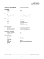
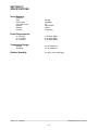
10. Specifications
67
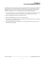
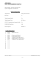
APPENDICES
S3012 Programming Example
RS-232 Pin-outs/Cables
S3012 User’s Manual
Appendix A
Appendix B
SYSTEMS Electronics Group
- iii -
SECTION 1
GENERAL DESCRIPTION
The S3012 Processor board is used as the primary processor in 4-card, 8-card, and 16-card S3000
systems. As the primary processor, the S3012 controls the S3000 bus, directing communications
between the S3012 and other intelligent I/O boards, reads and writes all basic I/O boards in the
system, and executes the user application program.
________________________________________________________________________________
1.1 PROGRAM DEVELOPMENT
Programming is implemented using SYSdev, an IBM PC or compatible software package that
allows the user to create, document, and compile the user application program as well as directly
interface with the S3012 for program download and online monitoring. The program is developed
off-line, compiled, then down loaded into the S3012 (S3012-BR only) or programmed into
EPROMS for installation in the S3012 (S3012-EP only). SYSdev allows the S3012 to be
programmed in a combination of languages: Ladder, High-level (subset of ‘C’) and Assembly
(MCS-96).
________________________________________________________________________________
1.2 PROGRAM EXECUTION TIMES
Typical program scan times are on the order of 0.25 milliseconds per 1K bytes program memory.
This is true for the Ladder instructions as well as High-level instructions. The main program
overhead execution time (I/O update, house keeping, etc.) is approximately 0.25 to 0.30
milliseconds. Thus main program scan times of under one millisecond are easily achievable (main
program size less than 3K). Using the high speed timed interrupt, system through-puts as low as
0.25 milliseconds are also possible.
________________________________________________________________________________
1.3 I/O ADDRESSING
I/O address capability is 16 I/O slots or 256 I/O points when using 16 point I/O boards. All basic
I/O (16 point inputs, 16 point outputs, etc.) is automatically read and written at the beginning of the
main program scan and saved in I/O image registers. In addition to the basic I/O boards, the S3012
can communicate to intelligent I/O boards (boards which contain their own processors) mounted in
the S3000 rack. This is done in a free-form fashion using system functions, which allows any
number of bytes to be transferred to and from the intelligent I/O.
S3012 User’s Manual
SYSTEMS Electronics Group
-1-
SECTION 1
GENERAL DESCRIPTION
________________________________________________________________________________
1.4 RS-232 PORTS
The S3012 contains two RS-232 ports: the PROG PORT and the USER PORT. The PROG PORT is
dedicated for program download, online monitoring and general interface to an IBM PC or
compatible running SYSdev. The USER PORT is available as a general RS-232 port for use as
defined by the user. Under software control of the user application program, communications to
any other RS-232 based device can be established. Typical applications are communications to
operator workstations or displays for system status or data acquisition.
________________________________________________________________________________
1.5 SERIAL NETWORK INTERFACE
When the optional serial network interface is installed, up to 32 S3012s can communicate with each
other, effectively providing a means to expand the I/O capabilities of the S3012 beyond one 16 slot
rack. The serial network is a high speed (344KBPS), twisted pair cable network configured in a
master/slave topology.
________________________________________________________________________________
1.6 FAULT DETECTION/DIAGNOSTICS
Internal to the S3012 are a series of comprehensive fault detection routines which verify the proper
operation of the S3012 at all times. Each detected fault has a corresponding fault code which can be
viewed using SYSdev, providing a description of the fault and recommended corrective action. In
addition to the fault detection routines, a hardware confidence test is resident in the S3012. This test
is the same test used at the factory to verify proper hardware operation and provides a complete
hardware verification of the S3012 board. This test is initiated through SYSdev.
S3012 User’s Manual
SYSTEMS Electronics Group
-2-
SECTION 1
GENERAL DESCRIPTION
________________________________________________________________________________
1.7 LED STATUS INDICATIONS
The following three status LEDs are located on the S3012 faceplate. PWR, RUN, and FLT. In
addition, S3012s equipped with a network interface option board (SPB3012-1, etc.) are provided
with a COMM LED. The definitions of these LEDs are as follows:
PWR: "On" when S3000 rack power is applied to the S3012.
RUN: "On" steady when the S3012 is executing a valid user's application program. "Off" when an
internal fault is detected or when a valid user’s program has not been loaded. The RUN led is
flashed during program download and also when the S3012 hardware confidence test is executed.
FLT: "On" when an internally detected fault has occurred in the S3012. See section 7 for more
details on the S3012 fault routine and error codes.
COMM: This LED is flashed every time an access to the S3000 serial network is made by any
S3000 board on the network. If the LED is on solid, continuous communications is occurring on the
network. If the LED is "off", no communications is occurring. This is not a fault LED but simply an
indication of activity on the S3000 network.
________________________________________________________________________________
1.8 S3012 VERSIONS (S3012-BR and S3012-EP)
Two versions of the S3012 are available: the S3012-BR and S3012-EP. The S3012-BR contains
44K bytes of battery backed CMOS RAM program memory while the S3012-EP contains 44K
bytes of EPROM program memory (implemented with 2ea 27C256 EPROMS). The S3012-BR is
used when faster program development times and ease of use are essential while the S3012-EP is
used when program security is of the utmost importance. Both versions are 100% compatible with
regard to user program development. Both versions contain 8K bytes of data memory in which 992
flags (single bit variables) reside, along with the remainder of data memory which can be referenced
as bytes or words. All but 124 of the data bytes are battery backed for data retention at power-down.
The S3012 is also available in a third product, the S3013. This product is actually a combination of
three boards: the S3012 processor board, the S3007 power supply, and the S3013 VME gateway
board. The three boards are mounted together, as one module, which is used to provide a
mechanism for the S3012 to communicate, at high speed, with VME based processors.
S3012 User’s Manual
SYSTEMS Electronics Group
-3-
SECTION 1
GENERAL DESCRIPTION
(This Page Intentionally Left Blank)
S3012 User’s Manual
SYSTEMS Electronics Group
-4-
SECTION 2
PROGRAM STRUCTURE
________________________________________________________________________________
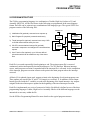
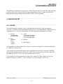
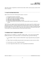
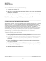
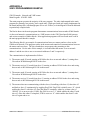
2.0 PROGRAM STRUCTURE
The SYSdev programming language is a combination of Ladder, High-level (subset of C) and
Assembly (MCS-96). All the files shown in the following are programmed in the same language
format. Each file can be written in any combination of the language types. The typical S3012 user
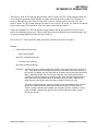
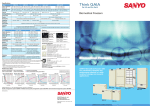
program consists of the following files:
POWER-UP
1) Initialization file (optional): executed once at power up.
2) Main Program file (required): scanned continuously.
INIT
FILE
TIMED
INTERRUPT
MAIN
PROG
FILE
CO-CPU
INTERRUPT
3) Timed Interrupt file (optional): executed once every 0.250
to 65.000 milliseconds as set by the user.
4) CO-CPU communications Interrupt file (optional):
executed in response to an intelligent I/O communications
request.
5) User Function files (optional): up to 100 user defined
subroutines which can be called from any of the above
files.
UFUNC
Each file is executed sequentially from beginning to end. The main program file is executed
continuously unless interrupted by the timed interrupt or CO-CPU interrupt. When an interrupt
occurs, main program execution is suspended while the interrupt file is executed. At the completion
of the interrupt, program execution resumes at the point in the main program where the interrupt
occurred.
All basic I/O is updated (inputs read, outputs written) at the beginning of each main program scan.
These updates are stored in the 'X' and 'Y' I/O images (see section 4.1). In addition, selected input
boards (specified with the 'I' variable) are read at the beginning of the timed interrupt. Any outputs
assigned in the timed interrupt are updated at the beginning of the timed interrupt execution.
Each file is implemented as a series of consecutive blocks. Each block is defined as one of the three
programming languages: Ladder, High-level or Assembly. Blocks of the different languages can be
intermixed as necessary within the file.
See the SYSdev Programming Manual for more details on the typical program structure.
S3012 User’s Manual
SYSTEMS Electronics Group
-5-
SECTION 2
PROGRAM STRUCTURE
(This Page Intentionally Left Blank)
S3012 User’s Manual
SYSTEMS Electronics Group
-6-
SECTION 3
SYSTEM CONFIGURATION
The system configuration defines the system or environment that the S3012 program will run in.
This includes: defining the rack size, I/O slot assignments, whether the timed interrupt is used and
the time interval if it is, whether the CO-CPU comm interrupt is used, the USER PORT baud rate
and the serial network option. This parameters are all set through SYSdev when the program is
developed. See the SYSdev Programming Manual for more details.
________________________________________________________________________________
3.1 RACK SIZE
This is the rack size used in the system. Choices are 4, 8, and 16 slots. The rack size is the number
of I/O boards that can be used, the S3012 and power supply is not included in the rack size. The
corresponding S3000 part numbers for the various rack sizes are:
S3004CHR: 4 slot rack chassis
S3008CHR: 8 slot rack chassis
S3016CHR: 16 slot rack chassis
When using the hybrid VME/S3000 rack chassis (part numbers S30XXVMEX), select the 16 slot
rack chassis for the rack size.
________________________________________________________________________________
3.2 I/O SLOT ASSIGNMENTS
Each I/O slot in the rack must be assigned the board that will go in that slot. This is required in
order for the compiler to generate the proper I/O reads and writes to the proper slots. Only the slots
which actually contain inputs are read and only the slots that contain outputs are written. This
reduces the overhead execution time by eliminating unnecessary I/O updates. It is also necessary to
define the location of intelligent I/O such that communications with these boards can be enabled.
See the SYSdev manual for the I/O board selections.
________________________________________________________________________________
3.3 TIMED INTERRUPT
If the timed interrupt file is to be used, it must be enabled in the configuration. This informs the
compiler to look for and compile the timed interrupt file with the rest of the program. The timed
interrupt time interval must also be set between 0.250 and 65.000 milliseconds. The resolution of
this time is .001 milliseconds.
Note: The timed interrupt file execution time must be less than the timed interrupt time interval,
otherwise a main program watchdog timer time out will occur.
S3012 User’s Manual
SYSTEMS Electronics Group
-7-
SECTION 3
SYSTEM CONFIGURATION
________________________________________________________________________________
3.4 CO-CPU COMM INTERRUPT
If any intelligent I/O boards in the system are to interrupt the S3012, via sfunc05, the CO-CPU
comm interrupt must be enabled in the configuration. This informs the compiler to look for and
compile the CO-CPU interrupt file along with the rest of the program.
________________________________________________________________________________
3.5 USER PORT BAUD RATE
The USER PORT baud rate can be set to any of the following baud rates: 300, 600, 1200, 2400,
4800, or 9600. The USER PORT baud rate must match the baud rate of the user device connected to
the USER PORT. The default baud rate is 9600.
________________________________________________________________________________
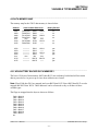
3.6 NETWORK BAUD RATE
Three serial network baud rates are available:
344KBPS (bits per second)
229KBPS
106KBPS
Note: All the boards connected on the network must be set to the same baud rate, otherwise a
communications error will occur.
For the most part, the baud rate is set as a function of the total network distance. The longer the
network distance, the slower the baud rate. As a general rule, the baud rate can be set as follows:
344KBPS – Network distance of 1,000 feet or less.
229KBPS – Network distance of 2,000 feet or less.
106KBPS – Network distance of 4,000 feet or less.
The S3012 must have an SPB3012-1 network board installed in order to interface with the network.
S3012 User’s Manual
SYSTEMS Electronics Group
-8-
SECTION 4
VARIABLE TYPES/MEMORY MAP
________________________________________________________________________________
4.1 VARIABLES
Three classes of variables are used in the S3012. They are: bits, bytes, and words. Bits are a single
bit in width and can have a value of 0 or 1. Bytes are 8 bits in width and can have a value between 0
and 255 decimal or 0 and ffH hex. Words are 16 bits in width and can have a value of 0 to 65535
decimal or 0 to ffffH hex. All numbers (values in variables and constants) are unsigned integer
values. No signed or floating point numbers are supported. Numbers can be represented as decimal
or hex (suffix ‘H’ following number).
Six different variable types are available in the S3012: flags (F), bytes (B), words (W), inputs (X),
timed interrupt inputs (I) and outputs (Y).
________________________________________________________________________________
4.1.1 FLAGS (F)
Flags are single bit variables which are generally used as internal coils or flags in the user program.
Flags can have a value of “0” or “1”. The S3012 contains 992 flags.
The format of the flag variable is:
Fzzz where:
zzz is a three digit flag
address (000 to 991).
Note: The leading ‘F’ must be a capital letter and that the flag address must be three digits (include
leading zeros as necessary).
Examples: F000, F012, F991, etc.
S3012 User’s Manual
SYSTEMS Electronics Group
-9-
SECTION 4
VARIABLE TYPES/MEMORY MAP
________________________________________________________________________________
4.1.2 BYTES (B)
Byte variables are 8 bit variables used as general purpose variables in the user program. Byte
variables can have a value between 0 and 255 decimal or 0 and ffH hex. Byte variables are used as
arithmetic variables in the High-level language, timer/counter presets and accumulators as well as
shift register bytes in the ladder language. The S3012 contains 7,788 'B' variables.
The format of the byte variable is:
Bzzz where:
zzz is the three or four
digit byte address (032
thru 155 and 512 thru
8175).
Note: The leading ‘B’ must be a capital letter and that zzz must be a three or four digit address
(include leading zeros as necessary).
Examples: B032, B150, B8000, etc.
Individual bits within the byte can also be referenced by simply appending a ‘.’ followed by the bit
number (0-7) to the byte address. The form of this is:
Bzzz.y where: zzz is the byte address
and y is the bit (0-7).
This allows any bit in the entire data memory to be referenced just as a flag is referenced. These
“byte.bit” variables can be used in ladder blocks as contact and coil variables as well as in the Highlevel blocks. Execution times for instructions that use bits within a byte are longer than execution
times for instructions using flags. Keep this in mind when using “byte.bit” references.
Examples: B080.0, B1000.7, B512.4, etc.
S3012 User’s Manual
SYSTEMS Electronics Group
- 10 -
SECTION 4
VARIABLE TYPES/MEMORY MAP
________________________________________________________________________________
4.1.3 WORDS (W)
Word variables are 16 bit variables used as general purpose variables in the user program. Words
can have a value between 0 and 65535 decimal or 0 and ffffH hex. Word variables are used as
arithmetic variables in the High-level language, timer/counter presets and accumulators as well as
shift register words in the ladder language. The S3012 contains 3,894 'W' variables.
The format of the word variable is:
Wzzz where:
zzz is the three or four digit
word address (032 thru 154 and
512 thru 8174).
Note: The leading ‘W’ must be a capital letter and that zzz must be a three or four digit address
(include leading zeros as necessary). Also, word addresses are always an even number (divisible by
2).
Examples: W034, W600, W7500, etc.
________________________________________________________________________________
4.1.4 INPUTS (X)
Input variables are bytes that contain the data read from the input boards during the main program
I/O update. One 'X' byte is allocated for each rack input byte, thus an S3063 16-point input board
has two 'X' bytes allocated for it, one byte for inputs 00 thru 07 and one byte for inputs 10 thru 17.
The input bytes are allocated based on the I/O slot assignments made in the system configuration
(see section 3.2). The input bytes reside in the I/O image table of data memory and can only be
accessed using the 'X' variable designation.
The format for the input byte is:
Xaab where:
aa is the two digit slot
address (00-15) and b is
the byte at the slot (0 or 1).
Note: The 'X' must be a capital letter and that the slot address must be two digits (add leading zeros
as required). Also, 'X' variables can only be referenced for input boards that are actually included in
the system configuration. Any reference to input variables that do not correspond to existing input
boards will result in a compiler error.
S3012 User’s Manual
SYSTEMS Electronics Group
- 11 -
SECTION 4
VARIABLE TYPES/MEMORY MAP
As with byte variables, individual bits within the 'X' variable can be referenced. These bits
correspond to the respective I/O point on the input board. The form of this is:
Xaab.c where: aa is the slot address, b is
the byte at the slot and c is
the bit or input point.
Examples: X010, X151, X020.5, X000.7, etc.
________________________________________________________________________________
4.1.5 TIMED INTERRUPT INPUTS (I)
Timed Interrupt input variables are bytes that contain the data read from input boards at the
beginning of the timed interrupt. Not all input boards are read at the beginning of the timed
interrupt, only the boards which are referenced with the 'I' variable in the timed interrupt file. This
provides a mechanism for the timed interrupt to obtain the most recent input data from selected high
speed inputs. Any input board specified in the system configuration can be referenced using the 'I'
variable. When any input point is referenced with the 'I' variable, the entire input board is read at the
beginning of the timed interrupt. The 'I' variable can only be used in the timed interrupt file, any
reference to the 'I' variable in the main program file will result in a compiler error.
The format for the 'I' variable is:
Iaab where:
aa is the two digit slot
address (00-15) and b is
the byte at the slot (0 or 1).
Note: The 'I' must be a capital letter and that the slot address must be two digits (add leading zeros
as required). Also, 'I' variables can only be referenced for input boards that are actually included in
the system configuration. Any reference to input variables that do not correspond to existing input
boards will result in a compiler error. ‘I’ variables can only be referenced in the timed interrupt file.
As with byte variables, individual bits within the 'I' variable can be referenced. These bits
correspond to the respective I/O point on the input board. The form of this is:
Iaab.c where:
aa is the slot address, b is
the byte at the slot and c is
the bit or input point.
Examples: I010, I151, I020.5, I000.7, etc.
S3012 User’s Manual
SYSTEMS Electronics Group
- 12 -
SECTION 4
VARIABLE TYPES/MEMORY MAP
________________________________________________________________________________
4.1.6 OUTPUTS (Y)
Output variables are bytes which contain the data that is written to output boards at the beginning of
the main program I/O update or timed interrupt execution. One 'Y' variable is allocated for each
output byte, thus an S3073 16-point output board has two 'Y' variables allocated for it, one byte for
outputs 00 thru 07 and one byte for outputs 10 thru 17. The output bytes are allocated based on the
I/O slot assignments made in the system configuration (see section 3.2).
Output variables can only be assigned (used as coils) in the main program or timed interrupt file. If
an output variable is assigned in the timed interrupt file, the entire output board will be updated at
the beginning of the timed interrupt execution. This provides a mechanism for high speed outputs,
assigned in the timed interrupt file, to be updated quickly as a function of the timed interrupt logic.
If none of the output points in a given output board are assigned in the timed interrupt, then the
output board is updated during the main program I/O update.
The format for the 'Y' variable is:
Yaab where:
aa is the two digit slot
address (00-15) and b is
the byte at the slot (0 or 1).
Note: The ‘Y’ must be a capital letter and that the slot address must be two digits (add leading
zeros as required). Also, 'Y' variables can only be referenced for output boards that are actually
included in the system configuration. Any reference to output variables that do not correspond to
existing output boards will result in a compiler error. 'Y' variables can only be assigned (used as
coils) in the main program or timed interrupt file but can be referenced (used as contacts) in any
file.
As with byte variables, individual bits within the 'Y' variable can be referenced. These bits
correspond to the respective I/O point on the output board. The form of this is:
Yaab.c where: aa is the slot address, b is
the byte at the slot and c is
the bit or output point.
Examples: Y030, Y141, Y051.5, Y100.7, etc.
S3012 User’s Manual
SYSTEMS Electronics Group
- 13 -
SECTION 4
VARIABLE TYPES/MEMORY MAP
________________________________________________________________________________
4.1.7 CONSTANTS
Constants are used as fixed numbers in High-level arithmetic and conditional statements as well as
for presets in timer/counters in ladder blocks.
In High-level blocks, constants can be represented in decimal or hex. If the number is decimal, the
constant is simply entered as the number to be referenced. No prefix or suffix is specified. If the
number is hex, the suffix ‘H’ is added immediately following the hex number. Examples of both
are:
25
25657
aeH
f000H
(decimal)
(decimal)
(hex)
(hex)
The hex letters (a,b,c,d,e,f) are case sensitive and must be typed as lower case letters. The hex suffix
is also case sensitive and must be typed as a capital letter (H).
All constants are unsigned integers. When the variable class is byte, the range of values is 0 to 255
decimal or 0 to ffH hex. If the variable class is word, the range of values is 0 to 65535 decimal or 0
to ffffH hex.
In ladder blocks, the only constants allowed are in timer/counter presets. In this case, they are
specified in decimal and preceded with the prefix ‘#’. If the timer/counter accumulator is a byte (B),
the range of presets is 0 to 255. If the accumulator is a word (W), the range is 0 to 65535.
S3012 User’s Manual
SYSTEMS Electronics Group
- 14 -
SECTION 4
VARIABLE TYPES/MEMORY MAP
________________________________________________________________________________
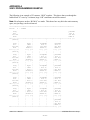
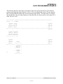
4.2 DATA MEMORY MAP
The memory map for the S3012 data memory is shown below:
Address
Valid Variable References
Battery Backed
0032
0033
0034
0035
thru
0154
0155
F000-F007
F008-F015
F016-F023
F024-F031
thru
F976-F983
F984-F991
B032
B033
B034
B035
thru
B154
B155
W032
——
W034
——
thru
W154
——
no
no
no
no
0512
0513
0514
0515
thru
8174
8175
————
————
————
————
thru
————
————
B512
B513
B514
B515
thru
B8174
B8175
W512
——
W514
——
thru
W8174
——
yes
yes
yes
yes
no
no
yes
yes
________________________________________________________________________________
4.2.1 NON BATTERY BACKED DATA MEMEORY
The lower 124 bytes of data memory (B032 thru B155) are not battery backed and will not retain
data at power down. At power-up or reset, these addresses are cleared.
Note: Flags F000 thru F991 are mapped into bytes B032 thru B155. Bytes B032 thru B155 are also
mapped into W032 thru W154. These addresses can be referenced as any or all three of these
variable types.
The flags are mapped into the bytes as shown as follows:
F000 = B032.0
F001 = B032.1
F002 = B032.2
F003 = B032.3
F004 = B032.4
F005 = B032.5
F006 = B032.6
F007 = B032.7
F008 = B033.0
F009 = B033.1
etc.
S3012 User’s Manual
SYSTEMS Electronics Group
- 15 -
SECTION 4
VARIABLE TYPES/MEMORY MAP
The bytes are mapped into the words with the even byte address as the low byte (lower 256
significance) of the respective word and the odd byte address as the upper byte (upper 256
significance) of the word as shown:
B032 = W032 (low byte)
B033 = W032 (high byte)
________________________________________________________________________________
4.2.2 BATTERY BACKED DATA MEMORY (B512-B8175)
The upper 7,764 bytes of data memory (B512 thru B8175) are battery backed such that all data
residing in this part of memory at power down is retained while power is off. At power up these
addresses are not cleared, retaining the data that was present before power down. The data in this
memory space can also be saved on disk using the “data upload” menu selection from the SYSdev
Target Board Interface menu. The data saved on disk can be down loaded to other S3012s using the
“data download” selection. See the SYSdev Programming Manual for details.
The upper group of memory is referenced as bytes (B) or words (W), no flags are resident in this
area of memory. However any bit within this area can be referenced using the "byte.bit" format
outlined in section 4.1.2. The byte (B) variables are mapped into the word (W) variables just as they
are in the lower group of memory.
________________________________________________________________________________
4.2.3 INTERRUPTING CO-CPU (B8175)
Byte address B8175 is a special function register that contains the slot number of the CO-CPU
which initiated the CO-CPU comm interrupt. This address can be tested inside the CO-CPU comm
interrupt file, with the appropriate sfunc06 executed based on the slot number in this register.
B8175 should not be used by the user program for any other purpose. See section 6.1.1 for more
details.
S3012 User’s Manual
SYSTEMS Electronics Group
- 16 -
SECTION 5
PROGRAMMING REFERENCE
The following sections provide an overview of the SYSdev instruction set and the system functions
available in the S3012. See the SYSdev Programming Manual for more details on the SYSdev
programming language and the operation of the SYSdev software package.
________________________________________________________________________________
5.1 INSTRUCTION SET
________________________________________________________________________________
5.1.1 LADDER
The ladder language is generally used to implement the boolean logic of the user program.
Networks of virtually any form (including nested branches) can be implemented. Ladder blocks are
implemented as a 7 row X 9 column matrix. The following ladder instructions are available:
1) Contacts
- Normally open
- Normally closed
2) Coils
- Standard
- Latch
- Unlatch
- Inverted
3) Timers
- 0.01 second time base
- 0.10 second time base
- 1.00 second time base
4) Counters
5) Shift Registers
Valid variables for contacts and coils are flags (F) or bits out of inputs (X), timed interrupt inputs
(I), outputs (Y) and bytes (B).
Valid variables for timer/counter presets and accumulators are bytes (B) or words (W). Both the
preset and accumulator must be of the same variable class (byte or word). If the class is byte, the
maximum preset is 255. If it is word, the maximum preset is 65535.
Valid variables for shift registers are also bytes (B) or words (W). If the variable is a byte, the
number of shifts per variable is 7. If the variable is a word, the number of shifts is 15.
S3012 User’s Manual
SYSTEMS Electronics Group
- 17 -
SECTION 5
PROGRAMMING REFERENCE
________________________________________________________________________________
5.1.2 HIGH-LEVEL (C)
The High-level language is a subset of the ‘C’ programming language. High-level is used for all
arithmetic, comparisons, conditional program execution, program looping, calling user functions
(subroutines) and calling system functions (I/O operations). High-level blocks are implemented as a
57 row X 80 column text array.
The High-level language incorporates the following:
1) Operators:
+:
-:
*:
/:
%:
<<:
>>:
&:
|:
^:
&&:
||:
add
subtract
multiply
divide
remainder
left shift
right shift
bitwise AND
bitwise OR
bitwise EX-OR
logical AND
logical OR
++:
—:
==:
>:
>=:
<:
<=:
!=:
~:
*:
&:
=:
increment
decrement
equate
greater than
greater than or equal
less than
less than or equal
not equal
complement
indirection (unary)
address operator
equal (assignment)
2) Statements:
- program statements (equations)
- conditional program execution (“if else-if else”)
- program looping (“for”, ”while”, and “do while” loops)
- unconditional program jumping (“goto”)
- user function calls (“ufuncXX” subroutines)
- system function calls (“sfuncXX” I/O operations)
________________________________________________________________________________
5.1.3 ASSEMBLY
The Assembly language conforms to the Intel MCS-96 instruction set. The assembler syntax
conforms to the UNIX system V assembler syntax.
S3012 User’s Manual
SYSTEMS Electronics Group
- 18 -
SECTION 5
PROGRAMMING REFERENCE
________________________________________________________________________________
5.2 SYSTEM FUNCTIONS
System functions provide the user with a means to perform extended I/O functions such as
communication to intelligent I/O boards, communication through the RS-232 USER PORT,
communication on the serial network, etc. A summary of the system functions available in the
S3012 is as follows:
sfunc03:
sfunc05:
sfunc06:
sfunc09:
sfunc10:
sfunc11:
sfunc12:
sfunc13:
sfunc14:
sfunc15:
sfunc16:
sfunc17:
watchdog timer reset
intelligent I/O communications initiate
intelligent I/O communications respond
system fault routine
RS-232 USER PORT receive
RS-232 USER PORT transmit
intelligent I/O block communications
serial network communications
VME dual-port RAM block read/write
VME dual-port RAM byte read
VME dual-port RAM byte write
simultaneous sfunc status
System functions are entered in high-level blocks as text. Each system function has a parameter list
associated with the system function call which defines such things as the address to read/write to,
the number of bytes to send/receive, etc. In addition, some system functions return with an error
code or function status which can be used to determine if the system function was successful, busy,
etc.
S3012 User’s Manual
SYSTEMS Electronics Group
- 19 -
SECTION 5
PROGRAMMING REFERENCE
________________________________________________________________________________
5.2.1 SYSTEM FUNCTION TYPES
Two types of system functions exist in the S3012: suspended and simultaneous.
Suspended System Function: Suspended system functions actually suspend program
execution while they are executed. Thus they are performed just as any other type of instruction, in
order of sequence in which they occur.
Simultaneous System Functions: Simultaneous system functions are executed simultaneously
to program execution. By their nature, simultaneous system functions may take multiple main
program scans to execute. These are basically “back-ground” tasks which are executed while the
user application program is executing, with insignificant impact on the user program scan time.
This type of system function returns with one of four types of return values when called: "Not
Busy", "Busy", "Done" or an error code representing a fault in the execution of the function. When
the function is first executed, a return value of "Busy" is returned. This indicates the function is
executing and is no longer available for use until it has completed. Subsequent calls to the same
system function will result in a "Busy" return value until the function has completed. At that time, a
call to the system function will result in either a "Done" return value or an error code value
representing a failure of the function to execute. The system function is now available to execute
again. See the individual system function formats following for more details on the return values
and error codes pertinent to each system function.
________________________________________________________________________________
5.2.2 sfunc03: WATCHDOG TIMER RESET
System function 03 resets the main program watchdog timer when called. The watchdog timer
normally times out if the main program scan time is longer than 40msec. This function can be used
to extend this time by 40msec every time sfunc03 is called. This desirable, for instance, if a long,
intentional program loop ("for" loop, "while" loop, etc.) is executed which would exceed the normal
40msec scan time.
General form:
sfunc03();
Parameters:
none
Return value:
none
Type:
suspended
Valid files:
Initialization, Main Program, Timed Interrupt, CO-CPU comm interrupt and User
functions.
S3012 User’s Manual
SYSTEMS Electronics Group
- 20 -
SECTION 5
PROGRAMMING REFERENCE
________________________________________________________________________________
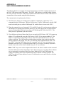
5.2.3 sfunc04: ASCII STRING LOAD COMMAND
System function 04 is used to convert the characters in an ascii string to their equivalent ascii codes
and store these codes in consecutive byte address in variable memory (Bxxx variables). System
function 04 is typically used in conjunction with the User port sfunc 11 transmit system function to
send ascii strings to operator interfaces, etc.
General form:
sfunc04(dest,”string”);
Parameters: dest = The address where the first ascii character of the string will be stored. The
remaining ascii characters will be stored in consecutive byte addresses following the
first byte address.
Variable Types: “B”
string = The string is from on to 60 printable characters. These characters will be converted
to their equivalent ascii codes and stored in consecutive byte addresses starting at
the dest byte address.
Note: The string must be enclosed with double quotes as shown (these double
quotes are not stored as part of the string, however, are simply used as delimiters
for the string).
Any printable character can be incorporated in the string with the exception of the
double quote “ or back slash \. If these two characters are to be incorporated in the
string, they must be preceded wit the back slash (i.e. \” will incorporate the “ only
and \\ will incorporate just on \)
Return Value:
none
Type:
Suspended
Valid Files:
Initialization, Main Program, Timed Interrupt, CO-CPU comm. Interrupt and User
functions
Examples
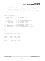
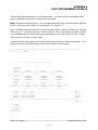
1) sfunc04(B100,”example #1”);
The above example will load the following byte addresses with the corresponding
ascii codes (numbers):
B100 = 101
B101 = 120
B102 = 97
B103 = 109
B104 = 112
B105 = 108
B106 = 101
B107 = 32
B108 = 35
B109 = 49
(ascii code for “e” = 101)
(ascii code for “x” = 120)
(ascii code for “a” = 97)
(ascii code for “m” = 109)
(ascii code for “p” = 112)
(ascii code for “l” = 108)
(ascii code for “e” = 101)
(ascii code for “ ” = 32)
(ascii code for “#” = 35)
(ascii code for “1” = 49)
S3012 User’s Manual
SYSTEMS Electronics Group
- 21 -
SECTION 5
PROGRAMMING REFERENCE
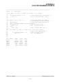
2) sfunc04(B2000,”:”);
The above example will load B2000 with 58 which is the ascii code for “:”.
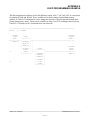
3) sfunc04(B120,”MOTOR \”on”\””);
The above example incorporates double quotes in the string and uses the back
slash to designate that these double quotes are part of the string and not the string
delimiters. The characters are stored in variable memory as follows:
B120 = 77
B121 = 79
B122 = 84
B123 = 79
B124 = 82
B125 = 32
B126 = 34
B127 = 111
B128 = 110
B129 = 34
(ascii code for “M” = 77)
(ascii code for “O” = 79)
(ascii code for “T” = 84)
(ascii code for “O” = 79)
(ascii code for “R” = 82)
(ascii code for “ ” = 32)
(ascii code for “ = 34)
(ascii code for “o” = 111)
(ascii code for “n” = 110)
(ascii code for “ = 34)
S3012 User’s Manual
SYSTEMS Electronics Group
- 22 -
SECTION 5
PROGRAMMING REFERENCE
________________________________________________________________________________
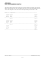
5.2.4 sfunc05 and sfunc06: INTELLIGENT I/O COMMUNICATIONS
System functions 05 and 06 are used for communications between the S3012 and other S3000
intelligent I/O (CO-CPU) boards. See section 6.1.1 for more details on the use of sfunc05 and
sfunc06.
General forms:
sfunc05(slot,#sent,srce,#rcve,dest);
sfunc06(slot,#rcve,dest,#sent,srce);
Parameters: slot = slot the intelligent I/O board resides in.
Variable type: constant (0-15).
#sent = The number of bytes to be sent to the intelligent I/O board.
Variable types: constant (0-128), 'B', or indirect 'B'.
srce = The address of the first byte to be sent. A consecutive number of bytes(= #sent) is
sent to the other board starting at this address.
Variable types: 'B 'or indirect 'B'.
#rcve = The number of bytes to be received from the other board.
Variable types: constant (0-128), 'B' or indirect ‘B’ (sfunc05 only).
#dest = The address where the first received byte is stored. A consecutive number of bytes
(= #rcve) is received from the other board and stored in a stack starting with this
address.
Variable types: 'B' or indirect 'B'.
Return value:
none
Type:
suspended
Valid files: sfunc05: Initialization, Main Program and Timed Interrupt
sfunc06: CO-CPU Comm file only
S3012 User’s Manual
SYSTEMS Electronics Group
- 23 -
SECTION 5
PROGRAMMING REFERENCE
________________________________________________________________________________
5.2.5 sfunc09: SYSTEM FAULT ROUTINE
System function 09 provides a means for the fault routine to be called in response to a software
detected fault from the user application program. The fault routine is executed as described in
section 7.1. The fault code will be set to 45H: sfunc09 generated fault.
Note: This function should only be called when a complete system shutdown is desired due to the
fact that program execution will cease.
General form:
sfunc09();
Parameters:
none
Return value:
none
Type:
non-returning
Valid files:
Initialization, Main Program, Timed interrupt, CO-CPU comm interrupt and User
functions.
________________________________________________________________________________
5.2.6 sfunc10: RS-232 USER PORT RECEIVE
System function 10 receives a consecutive number of bytes from the USER PORT. See section
6.2.1 for a detailed description of the use of sfunc10.
General form:
Parameters:
sfunc10(#rcve,dest);
#rcve = The number of bytes to be received thru the USER PORT.
Variable types: constant(1-250), 'B' or indirect 'B'.
dest = The address where the first byte received will be stored. A consecutive number of
bytes(= #rcve) is received thru the USER PORT and stored in a stack starting
with this address.
Variable types: 'B' or indirect 'B'.
Return Values:
0=
1=
2=
3=
NOT BUSY/READY
BUSY
DONE (receive successful)
TIME OUT (bytes not received)
Type:
simultaneous
Valid files:
Initialization and Main Program only
S3012 User’s Manual
SYSTEMS Electronics Group
- 24 -
SECTION 5
PROGRAMMING REFERENCE
________________________________________________________________________________
5.2.7 sfunc11: RS-232 USER PORT TRANSMIT
System function 11 transmits a consecutive number of bytes out the USER PORT. See section 6.2.2
for a detailed description of the use of sfunc11.
General form:
Parameters:
sfunc11(#sent,srce);
#sent = The number of bytes to transmit out the USER PORT.
Variable types: constant (1-250), 'B' or indirect 'B'.
srce = The address where the first byte transmitted is stored. A consecutive number of
bytes (= #sent) is transmitted out the USER PORT starting with this address.
Variable types: 'B' or indirect 'B'.
Return Values:
0=
1=
2=
3=
NOT BUSY/READY
BUSY
DONE (transmit successful)
TIME OUT (bytes not sent)
Type:
simultaneous
Valid files:
Initialization and Main Program only
S3012 User’s Manual
SYSTEMS Electronics Group
- 25 -
SECTION 5
PROGRAMMING REFERENCE
________________________________________________________________________________
5.2.8 sfunc12: INTELLIGENT I/O BLOCK COMMUNICATIONS
System function 12 is used to communicate with intelligent I/O boards equipped with a comm block
buffer (versus the standard bus interface used with intelligent I/O boards communicating using
sfunc05 and sfunc06). See section 6.1.2 for more details on the use of sfunc12.
General form:
sfunc12(slot,#sent,srce,#rcve,dest);
Parameters:
slot = Slot the intelligent I/O board resides in.
Variable type: constant (0-15).
#sent = Number of words to be sent to the intelligent I/O board.
Variable types: constant (0-120), 'W' or indirect 'W'.
srce = The address where the first word to be sent is stored. A consecutive number of
words (= #sent) is sent to the I/O board starting at this address.
Variable type: 'W' or indirect 'W'.
#rcve = Number of words to be received from intelligent I/O board.
Variable types: constant (0-120), 'W' or indirect 'W'.
dest = The address where the first word received will be stored. A consecutive number
of words (= #rcve) is received from the other board and saved in a stack starting
at this address.
Variable types: 'W' or indirect 'W'.
Return Values:
0=
1=
2=
3=
4=
NOT BUSY/READY
BUSY
DONE (send/rcve successful)
TIME OUT (intelligent I/O board did not respond)
BAD ACKNOWLEDGE (intelligent I/O board did not acknowledge communication
attempt)
Type:
simultaneous
Valid files:
Initialization and Main Program only
S3012 User’s Manual
SYSTEMS Electronics Group
- 26 -
SECTION 5
PROGRAMMING REFERENCE
________________________________________________________________________________
5.2.9 sfunc13: SERIAL NETWORK COMMUNICATIONS
System function 13 is used to communicate to other S3012s or nodes on the serial communication
network. See section 6.3 for details on the use of sfunc13 and a description of the serial network.
General form:
sfunc13(slave,#sent,s_srce,s_dest,#rcve,r_srce,r_dest);
Parameters:
slave = Address of node to communicate with. This is the network address of the slave,
each slave has a unique address.
Variable type: constant (1-32), 'B' or indirect 'B'.
#sent = Number of words to send to slave.
Variable types: constant (0-120),'B' or indirect 'B'
s_srce = Address of send stack in master which will be sent to slave. A consecutive
number of words(= #sent) will be sent to the slave starting at this address.
Variable type: 'W' or indirect 'W'.
s_dest = Starting address of stack in slave where words sent from master will be stored.
Variable type: 'W' or indirect 'W'.
#rcve = Number of words received from slave.
Variable type: constant(0-120), 'B' or indirect 'B'.
r_srce = Starting address of stack in slave where words will be sent from slave to master.
Variable type: 'W' or indirect 'W'.
r_dest = Starting address in master where words sent from slave will be stored.
Variable type: 'W' or indirect 'W'.
Return values:
0=
1=
2=
3-10H =
NOT BUSY/READY
BUSY
DONE (comm with slave successful)
ERROR CODE (see section 7.4.1 for serial network communication error code
descriptions).
Type:
simultaneous
Valid files:
Initialization and Main Program only
S3012 User’s Manual
SYSTEMS Electronics Group
- 27 -
SECTION 5
PROGRAMMING REFERENCE
________________________________________________________________________________
5.2.10 sfunc14: VME DUAL-PORT RAM BLOCK READ/WRITE
System function 14 is used to read and write blocks of data to the VME dual-port RAM when the
S3012 is packaged in an S3013 VME Gateway. See section 6.4 for more details on the use of
sfunc14.
General form:
Parameters:
sfunc14(#sent,s_srce,s_dest,#rcve,r_srce,r_dest);
#sent = Number of words transferred to the VME dual-port RAM from theS3012.
Variable types: constant (0-255), 'W' or indirect 'W'.
s_srce = Starting address of stack to be transferred to the VME dual-port RAM. A
consecutive number of words (= #sent) is transferred starting with this address.
Variable types: 'W' or indirect 'W'.
s_dest = Starting address in VME dual-port RAM where the words sent are stored.
Variable types: constant (0-4094 even address) or indirect 'W'.
#rcve = Number of consecutive words transferred from the VME dual-port RAM to the
S3012.
Variable types: constant (0-255), 'W' or indirect 'W'.
r_srce = Starting address in VME dual-port RAM where words are to be transferred from
the VME dual port RAM to the S3012.
Variable types: constant (0-4094 even) or indirect 'W'.
r_dest = Starting address of stack inS3012 where the words from the VME dual-port RAM
are stored.
Variable types: 'W' or indirect 'W'.
Return value:
0 = sfunc14 transfer successful.
ffH = sfunc14 transfer not successful. Data transferred may not be valid.
Type:
suspended
Valid files:
Initialization and Main Program only
S3012 User’s Manual
SYSTEMS Electronics Group
- 28 -
SECTION 5
PROGRAMMING REFERENCE
________________________________________________________________________________
5.2.11 sfunc15: VME DUAL-PORT RAM BYTE READ
System function 15 is used to read a single byte from the VME dual-port RAM when the S3012 is
packaged in an S3013 VME gateway. See section 6.4 for more details on the use of sfunc15.
General form:
Parameters:
sfunc15(srce,dest);
srce = The byte address in the VME dual port RAM to be read.
Variable types: constant (0-4095) or indirect 'B'.
dest = Byte address in S3012 where data from VME dual-port RAM is to be stored.
Variable types: 'B' or indirect 'B'.
Return values:
0 = VME byte read successful.
ffH = VME byte read not successful, data may be invalid.
Type:
suspended
Valid files:
Initialization and Main Program only.
________________________________________________________________________________
5.2.12 sfunc16: VME DUAL-PORT RAM BYTE WRITE
System function 16 is used to write a single byte to the VME dual-port RAM when the S3012 is
packaged in an S3013 VME gateway. See section 6.4 for more details on the use of sfunc16.
General form:
Parameters:
sfunc16(dest,srce);
dest = The byte address in the VME dual port RAM to be written to.
Variable types: constant (0-4095) or indirect ‘B’.
srce = Byte address or data in S3012 to be written to VME dual-port RAM.
Variable types: constant (0-255)‘B’ or indirect ‘B’.
Return values:
0 = VME byte write successful.
ffH = VME byte write not successful, data in VME RAM may be invalid.
Type:
suspended
Valid files:
Initialization and Main Program only.
S3012 User’s Manual
SYSTEMS Electronics Group
- 29 -
SECTION 5
PROGRAMMING REFERENCE
________________________________________________________________________________
5.2.13 sfunc17: SIMULTANEOUS sfunc STATUS
System function 17 provides a means of checking the status of a simultaneous sfunc (sfunc10,11,12,
and 13) without having to call the particular sfunc. The return value of sfunc17 is the return value of
the specified sfunc (see return values for each type of simultaneous sfunc). Thus if the specified
sfunc is “BUSY”, sfunc17 returns with “BUSY” when called for that sfunc.
General form:
sfunc17(sfunc#);
Parameters: sfunc# = The number of the sfunc status to be checked.
Variable types: constant (10,11,12, or 13).
Return value:
return value of the specified sfunc (see each simultaneous sfunc for possible
return values).
Type:
suspended
Valid files:
Initialization and Main Program only.
Example:
If the status of sfunc13 is desired, the following program statement could be
executed:
B100 = sfunc17(13);
The status (return value) of sfunc13 would be placed in B100. The possible
range of return values would be the possible return values when sfunc13 is
called (i.e. 0=NOTBUSY, 1=BUSY, 2=DONE, 3-10H=ERROR CODE). B100
could then be checked to see what the status of sfunc13 is.
This provides an easy way to check the status of sfunc13 (or any other
simultaneous sfunc) without having to call sfunc13 again.
S3012 User’s Manual
SYSTEMS Electronics Group
- 30 -
SECTION 6
EXTENDED I/O OPERATIONS
________________________________________________________________________________
6.1 COMMUNICATIONS WITH INTELLIGENT (CO-CPU) I/O BOARDS
Intelligent I/O boards (here after abbreviated as “CO-CPUs”) are boards that contain their own
processors (micro controllers) and execute their own programs independent of the program
executed in the S3012. These boards reside in I/O slots of the S3000 rack just as I/O boards reside
in the rack. The bus interface of these boards is, however, different then the basic I/O boards and
thus communications with CO-CPU boards is different as well.
The S3012 uses system functions 5,6 and 12 to communicate with CO-CPU boards. This provides a
free-form mechanism to pass information back and forth between the S3012 and CO-CPUs. These
system functions specify a certain number of bytes (or words) to send to the CO-CPU from the
S3012 and vice versa.
Two types of bus interfaces exist in CO-CPUs: the standard CO-CPU bus interface and the buffered
CO-CPU bus interface. Standard bus interface CO-CPUs use sfunc05 and sfunc06 to communicate
while buffered CO-CPUs use sfunc12. The standard CO-CPU does not contain a comm buffer and
therefore handshakes data back and forth, at high speed, using the suspended sfuncs 05 and 06.
Buffered CO-CPUs contain an on-board bus interface buffer that allows a larger amount of data to
be transferred between the S3012 and CO-CPU using the simultaneous (“back-ground”) sfunc12.
All CO-CPUs incorporate the standard bus interface unless otherwise indicated on the respective
CO-CPU data sheet.
The following sections describe communications between CO-CPUs, with the different bus
interfaces, using sfunc05,06, and 12.
________________________________________________________________________________
6.1.1 STANDARD CO-CPU COMMUNICATIONS (sfunc05 and 06)
System functions 05 and 06 are used for communications with standard bus interface CO-CPUs.
These system functions are primarily used to send control data between the S3012 and CO-CPUs
and to initialize the CO-CPUs at power up. Communications (here after abbreviated as “comm”)
between the two boards is achieved by one board initiating the comm request and the other board
responding to the request. The two sfuncs are used in conjunction with each other where sfunc05 is
used to initiate comm while sfunc06 is used to respond.
Comm between the S3012 and a CO-CPU board can be initiated from either board. The S3012 can
initiate comm while the CO-CPU board responds, or the CO-CPU board can initiate comm while
the S3012 responds. In both cases, the board which initiates the comm will do so using sfunc05 in
it’s main program, while the board that responds will use the CO-CPU communications interrupt
file to interrupt it’s main program and respond with sfunc06.
S3012 User’s Manual
SYSTEMS Electronics Group
- 31 -
SECTION 6
EXTENDED I/O OPERATIONS
The following sequence of events occurs when an sfunc05/06 is performed:
1) Initiating board sends comm request to responding board.
2) Responding board interrupts it’s main program and enters CO-CPU interrupt file. Responding board
sends comm acknowledge to initiating board.
3) Initiating board sends a predefined number of consecutive bytes to responding board. Responding
board receives these bytes.
4) Responding board sends a predefined number of consecutive bytes to initiating board.
5) Communications is complete, initiating board continues executing it’s main program while
responding board returns from CO-CPU interrupt and continues to execute it’s main program.
The preceding sequence outlines that for each comm event, both the initiating board sends data to
the responding board and the responding board sends data to the initiating board. Data is sent both
directions regardless of which board initiated the comm request. The number of bytes sent between
the two boards must be in agreement on both sides. In other words, if the initiating board is
specified to send 6 bytes in it’s sfunc05 call, the responding board must be set to receive 6 bytes in
it’s sfunc06 call.
All standard bus interface CO-CPU boards in the system must be initialized at power-up with the
sfunc05/06 communications function. Each CO-CPU board is assigned an identifier such that when
a CO-CPU board initiates a comm request with the S3012, the S3012 can determine which COCPU initiated the request. The identifier assigned to a given CO-CPU is the slot number it resides in
and is automatically set during this initialization comm. The CO-CPU identifier is stored in address
B8175 when a CO-CPU initiates a request, allowing the user CO-CPU interrupt file to poll B8175
and determine which CO-CPU initiated the interrupt. The initialization comm is implemented by
placing an sfunc05 in the “init” file of the S3012 and placing an sfunc06 comm respond in the “init”
file of the CO-CPU board.
If an error occurs when sfunc05 or sfunc06 is called in the S3012, the fault routine is automatically
executed, saving the fault code and suspending S3012 program execution. See section 7 for details
on the fault routine and sfunc05 and sfunc06 error codes.
See section 5.2.3 for the general formats, parameters and return values of sfunc05 and sfunc06.
S3012 User’s Manual
SYSTEMS Electronics Group
- 32 -
SECTION 6
EXTENDED I/O OPERATIONS
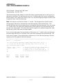
Examples:
1) Communications initiated from S3012 (interrupting CO-CPU):
S3012 main program:
sfunc05(4,4,B100,2,B120);
CO-CPU comm interrupt file:
sfunc06(0,4,B080,2,B084);
Execution: The S3012 initiates the comm request with a CO-CPU in slot 4, sends 4 bytes (B100,
B101, B102 and B103) to the CO-CPU, which stores these at B080, B081, B082 and
B083. The CO-CPU then sends 2 bytes (B084 and B085) to the S3012, which stores
these at B120 and B121.
2) Communications initiated from CO-CPU (interrupting S3012):
CO-CPU main program (CO-CPU in slot 3):
sfunc05(0,0,B032,5,B080);
S3012 comm interrupt file:
if (B8175 == 3)
sfunc06(3,0,B032,5,B110);
Execution: The CO-CPU in slot 3 initiates comm with the S3012, causing the CO-CPU interrupt file
to be entered in the S3012. The CO-CPU sends zero bytes to the S3012. The S3012
tests B8175 for CO-CPU identifier “3” (CO-CPU slot address 3), reads zero bytes from
the CO-CPU then sends 5 bytes (B110, B111, B112, B113, and B114). The CO-CPU
receives the 5 bytes and stores them at B080, B081, B082, B083, and B084
respectively.
S3012 User’s Manual
SYSTEMS Electronics Group
- 33 -
SECTION 6
EXTENDED I/O OPERATIONS
________________________________________________________________________________
6.1.2 BUFFERED CO-CPU COMMUNICATIONS (sfunc12)
System function 12 and the buffered CO-CPU comm interface was designed to allow larger
amounts of low priority data to be transferred to and from CO-CPUs without any significant impact
on program scan times. For this reason, sfunc12 is a simultaneous sfunc that is executed
simultaneously to the user application program execution. The emphasis is not on the speed of
transmission but instead on transmitting a larger amount of data with minimal impact on scan time.
For this reason it may take multiple scans for sfunc12 to complete once it is initiated.
System function 12 communications between an S3012 and a CO-CPU board is always initiated
from the S3012. CO-CPUs equipped with the comm buffer interface cannot initiate the CO-CPU
comm interrupt in the S3012. For this reason, the sfunc12 is always placed in the main program of
the S3012 initiating comm, while the sfunc12 in the responding CO-CPU is placed in the CO-CPU
comm interrupt file.
The sequence of events in an sfunc12 comm event are as follows:
1) S3012 initiates comm with CO-CPU using sfunc12. Program execution in S3012 continues once
sfunc12 is called without waiting for a response from the CO-CPU.
2) As the S3012 user application program execution continues, the words to be sent from the S3012 to
the CO-CPU are transferred to the CO-CPU comm buffer. Both the S3012 and CO-CPU application
programs continue to execute while this transfer takes place.
3) Once all the words to be sent to the CO-CPU are transferred into the comm buffer, the comm
interrupt in the CO-CPU is initiated causing the CO-CPU interrupt file to be executed.
4) Inside the CO-CPU interrupt file, a corresponding sfunc12 is executed which reads all the words,
sent from the S3012, in the comm buffer and stores them in internal memory. The CO-CPU then
writes, to the comm buffer, the words that are to be sent back to the S3012. The CO-CPU then exits
the comm interrupt file and returns to executing the main CO-CPU program.
5) When the S3012 detects that the CO-CPU comm buffer has been loaded with the words to be read
from the CO-CPU, it begins reading these values from the comm buffer. This occurs while the
application program continues to execute. Once all the words have been read from the buffer, the
return value for sfunc12 is set to “DONE”. The sfunc12 comm event is now complete.
In the above sequence, once the sfunc12 in the S3012 is initiated, subsequent calls to the sfunc12
result in a return value of “BUSY” until all the words have been read from the CO-CPU in step (5).
At that point, a return value of "DONE" or an "ERROR CODE" is returned at the next sfunc12 call.
If the sfunc12 was successful, the return value is "DONE". If it was not, an error code is returned
representing the nature of the fault. See section 5.2.7 for more details on the return values. System
function 17 can also be used to read the status of sfunc12 to determine if it is "BUSY", "DONE",
etc. See section 5.2.12 for a description of sfunc17.
S3012 User’s Manual
SYSTEMS Electronics Group
- 34 -
SECTION 6
EXTENDED I/O OPERATIONS
The sfunc12 in the S3012 main program and the sfunc12 in the CO-CPU comm interrupt must also
be in complete agreement on the number of words sent from the S3012 to the CO-CPU and vice
versa. In other words, if the sfunc12 in the S3012 is set to send 20 words to the CO-CPU, the
sfunc12 in the CO-CPU comm interrupt file must be set to receive 20 words, etc. Failure to conform
to this requirement will result in an error code return value from the sfunc12.
Unlike the standard CO-CPU bus interface using sfunc05 and 06, the buffered CO-CPUs do not
need to be initialized at power up. These boards do not have an identifier associated with them, but
are instead simply addressed by the slot they reside in.
See section 5.2.7 for the general format, parameter list and return values of sfunc12.
Example:
1) Typical sfunc12 comm event:
S3012 main program:
sfunc12(7,30,W1000,20,W1100);
CO-CPU comm interrupt:
sfunc12(0,30,W040,20,W120);
Execution: The S3012 sends 30 words (W1000 thru W1058) to the comm buffer of the CO-CPU in
slot 7. Once all the words have been loaded in the comm buffer, the comm interrupt of
the CO-CPU is initiated, the CO-CPU reads the 30 words in the comm buffer and stores
them in W040 thru W098. The CO-CPU then loads the comm buffer with 20 words
(W120 thru W158) and exits the comm interrupt file. When the S3012 detects that the
comm buffer has been loaded with the 20 words from the CO-CPU, it reads the 20
words from the comm buffer and stores them in words W1100 thru W1138.
The S3012 continued program execution through-out the entire data transfer. Calls to
the sfunc12 made before the transfer was complete, resulted in a return value of
"BUSY". Once the transfer was complete, the next call to sfunc12 resulted in a return
value of "DONE", indicating the data from the CO-CPU had been loaded in words
W1100 thru W1138.
S3012 User’s Manual
SYSTEMS Electronics Group
- 35 -
SECTION 6
EXTENDED I/O OPERATIONS
________________________________________________________________________________
6.2 USER PORT (RS-232) COMMUNICATIONS
The USER PORT is a general purpose RS-232 port available for connection to any RS-232 user
devices. Typical applications include: S3012 connection to operator workstations, connection to
IBM PC or compatibles for system data acquisition, etc. Communications through the USER PORT
is achieved using sfunc10 (USER PORT read) and sfunc11 (USER PORT write). These sfuncs
allow any ascii codes from 0 to 255 to be read from or written to the port.
The baud rate of the user port is programmable to 300, 600, 1200, 2400, 4800, or 9600 Baud. This
is set in the system configuration (see section 3.5). The protocol of the port is fixed at: 1 start bit, 8
data bits, and 1 stop bit with no parity.
The hardware handshaking signals CTS (clear to send), RTS (request to send) and DTR (data
terminal ready) are all available and used as generally defined. DSR (data set ready) is not used by
the S3012 USER PORT.
________________________________________________________________________________
6.2.1 RECEIVING THROUGH THE USER PORT (sfunc10)
Using sfunc10, from 1 to 250 consecutive bytes can be received from the USER PORT in one
command. System function 10 is a simultaneous function such that once it is initiated, program
execution continues without waiting for the sfunc to complete. Subsequent calls of sfunc10 result in
a return value of "BUSY" until the sfunc completes (return = "DONE") or times out (return =
"TIME OUT"). Since sfunc10 is a simultaneous function, the impact on the user application
program scan time is negligible when an sfunc10 is executed.
The device connected to the USER PORT must send the data to the S3012 within a certain time
period once sfunc10 is initiated in order to avoid a return value of "TIME OUT". In most
applications, software handshaking will be required between the S3012 and user RS-232 device in
order to assure the proper number of bytes is sent at the proper time.
The parameters specified in sfunc10 are: the number of bytes to receive and the starting address of
the stack to store the bytes at. See section 5.2.5 for the general form, parameter list and return
values of sfunc10.
S3012 User’s Manual
SYSTEMS Electronics Group
- 36 -
SECTION 6
EXTENDED I/O OPERATIONS
________________________________________________________________________________
6.2.2 TRANSMITTING THROUGH THE USER PORT (sfunc11)
Using sfunc11, from 1 to 250 consecutive bytes can be transmitted out the USER PORT in one
command. System function 11 is a simultaneous function such that once it is initiated, program
execution continues without waiting for the sfunc to complete. Subsequent calls of sfunc11 result in
a return value of "BUSY" until the sfunc completes (return = "DONE") or times out (return =
"TIME OUT"). Since sfunc11 is a simultaneous function, the impact on the user application
program scan time is negligible when an sfunc11 is executed.
System function 11 uses the CTS (clear to send) signal to assure that the device receiving the data is
ready to receive the data. If CTS does not become active within a certain time period after sfunc11
is initiated, a return value of "TIME OUT" is obtained in the subsequent call of sfunc11. If the user
device does not use the CTS signal for hardware handshaking, then CTS must be jumpered to RTS
(request to send). See appendix B for the USER PORT pin-out.
The parameters specified in sfunc11 are: the number of bytes to transmit and the starting address of
the stack of bytes that will be transmitted. See section 5.2.6 for the general form, parameter list and
return values of sfunc11.
Examples:
1) Receiving through the USER PORT:
Main program:
B050 = sfunc10(20,B100);
Execution: The above receives 20 bytes from the USER PORT and stores them in B100 thru B119.
The return value of sfunc10 is stored in B050. When the sfunc10 is first called, the return
value will equal "BUSY" (B050 = 1). Subsequent calls of sfunc10 will result in a "BUSY"
(B050 = 1) return value until all 20 bytes have been received, at which time a return
value of "DONE" (B050 = 2) is obtained. If the device connected to the USER PORT
does not send any or all of the 20 bytes, a return value of "TIME OUT" (B050 = 3) is
obtained after a certain time period.
Note: Program execution is not suspended while sfunc10 is executing. Once initiated,
program execution continues with subsequent calls of sfunc10 or sfunc17(10)
determining when all 20 bytes have actually been received. The time it takes for sfunc10
to complete is a function of the selected USER PORT baud rate and the number of
bytes to be received.
S3012 User’s Manual
SYSTEMS Electronics Group
- 37 -
SECTION 6
EXTENDED I/O OPERATIONS
2) Transmitting out the USER PORT:
Main program:
B060 = sfunc11(30,B1000);
Execution: The above transmits the 30 bytes between B1000 and B1029 out the USER PORT. The
return value of sfunc11 is stored in B060. When the sfunc11 is first called, the return
value will equal "BUSY" (B060 = 1). Subsequent calls of sfunc11 will result in a “BUSY”
(B060 = 1) return value until all 30 bytes have been transmitted, at which time a return
value of "DONE" (B060 = 2) is obtained. If the device connected to the USER PORT is
not ready to receive (CTS not active) for a certain time period, a return value of "TIME
OUT" (B060 = 3) is obtained.
Note: Program execution is not suspended while sfunc11 is executing. Once initiated,
program execution continues with subsequent calls of sfunc11 or sfunc17(11)
determining when all 30 bytes have actually been transmitted. The time it takes for
sfunc11 to complete is a function of the selected USER PORT baud rate and the
number of bytes to be transmitted.
________________________________________________________________________________
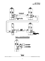
6.3 SERIAL NETWORK COMMUNICATIONS
The serial network provides a means for multiple S3012s to communicate with each other. The
network described in the following sections is the S3000-N1 network, but other S3000 networks
conform to the same general principles. An order for an S3012 to communicate on the S3000-N1
network, an SPB3012-1 option board must be mounted to the S3012. See section 9.3.1 for details on
adding the SPB3012-1.
The network operates in a master/slave topology. One S3012 acts as the master and controls all
communications on the network. The remaining S3012s act as slaves and simply respond to
communications requests from the master. The master can send up to 120 consecutive words and
receive up to 120 consecutive words from a slave in one command. If data is to be sent from one
slave to another slave, it must be done through the master (i.e. the master reads the data from the
first slave and then sends it to the second slave).
Up to 32 S3012s (or other S3000 network compatible boards) can be installed on one network.
These 32 nodes consist of the one master and up to 31 slaves. Each S3012 or node on the network is
assigned a unique network address. This number is a number between 1 and 32. The network
address is used to specify which slave the master is communicating to. The network address is set
in the S3012 from the SYSdev Target board Interface menu and is down loaded directly to the
S3012 from the IBM PC or compatible running SYSdev. See section 9.3.3.
S3012 User’s Manual
SYSTEMS Electronics Group
- 38 -
SECTION 6
EXTENDED I/O OPERATIONS
________________________________________________________________________________
6.3.1 COMMUNICATING ON THE NETWORK (sfunc13)
System function 13 is used to execute the communications command to the slave. The parameter
list of sfunc13 contains:
1)
2)
3)
4)
5)
6)
7)
Slave network address to communicate to
Number of words to be sent to slave
Starting address of stack, in master, of words which will be sent to slave.
Starting address of stack, in slave, where the words are to be stored.
Number of words to be received from slave
Starting address of stack, in slave, where the words will be sent from.
Starting address of stack, in master, where the words from the slave will be stored.
See section 5.2.8 for a complete description of the above parameters, the general form of sfunc13
and the return values possible with sfunc13.
Note: sfunc13 is used only in the master, the slaves respond to network communications
completely transparently. No commands are added to the slave programs in order to implement the
serial network. Thus, only one program (the master's) in the entire network has any commands
pertaining to network communications.
System function 13 is a simultaneous function such that once it is initiated, program execution
continues without waiting for the sfunc to complete. Subsequent calls of sfunc13 or sfunc17(13)
result in a return value of "BUSY" until the sfunc completes (return = "DONE") or detects an error
(return = "ERROR CODE"). See section 7.4.1 for a description of the serial network error codes.
Since sfunc13 is a simultaneous function, the impact on the user application program scan time is
negligible when executed. This is also true for the responding slave. Reception and transmission on
the serial network occurs concurrently with program execution, no significant increase in the scan
time of the slave occurs when a slave is communicated with.
The sequence of events in a serial network comm event are as follows:
1) Master S3012 initiates comm event by executing an sfunc13. Program execution in the master
proceeds concurrently with the transmission of the words to the slave.
2) The slave receives the words from the master concurrently with it's program execution. Once all
words are received from the master, the slave starts transmission of the words that are to be sent
from the slave to the master. This also occurs concurrently with the slave program execution.
3) The master receives the words sent from the slave concurrently with it's program execution. Once all
the words from the slave have been received, the subsequent call to sfunc13 results in a return
value of "DONE". Until this step, calls to sfunc13 would have resulted in a "BUSY" return value.
See section 9.3 for details on installing and wiring the network.
S3012 User’s Manual
SYSTEMS Electronics Group
- 39 -
SECTION 6
EXTENDED I/O OPERATIONS
Example:
1) Communicating from the master to a slave:
Master S3012 main program:
B080 = sfunc13(4,20,W1000,W5000,15,W5050,W1050);
Execution: The above command transmits 20 words (W1000 thru W1038) in the master to the slave
at network address 4, storing the data in W5000 thru W5038. The slave then transmits
15 words (W5050 thru W5078) to the master, storing this data at W1050 thru W1078.
The transmission of the data was done concurrently with the program executions of both
the master and the slave.
The return value of the sfunc13 is stored in B080. Once the sfunc13 is initiated, the
return value of the sfunc13 is "BUSY" (B080 = 1) until the transmission is complete. At
that time, the return value is "DONE" (B080 = 2) or an error code (B080 = ERROR
CODE) if an error occurred in transmission.
S3012 User’s Manual
SYSTEMS Electronics Group
- 40 -
SECTION 6
EXTENDED I/O OPERATIONS
________________________________________________________________________________
6.4 VME GATEWAY INTERFACE (S3013)
The S3013 VME Gateway module is a package which incorporates an S3012 processor board
mounted to a VME gateway board. The S3013 provides a gateway or bridge between the S3012
processor/S3000 bus and a VME bus. The VME gateway itself is a 4K byte dual-port memory
which both the S3012 can read/write to and a VME processor can read/write to. The package
contains three boards: the S3012 processor board which connects to the S3000 back plane, an
S3007 power supply which connects to the S3000 back plane and a VME gateway board which
connects to the VME back plane.
The purpose of the S3013 is to provide a high-speed mechanism for passing data between the S3012
and VME based processors. The S3012 can pass data to the VME processor by writing the data to
the gateway dual-port RAM, the VME processor then reads this data from the dual-port RAM. The
VME processor passes data to the S3012 simply by writing the data to the gateway dual-port RAM
where the S3012 can then read the data. Up to 4K bytes can be passed in one transfer cycle.
Collisions in the dual-port RAM (access to the same dual-port RAM address by both sides
simultaneously) is detected and handled by hardware on the VME side and detected by software on
the S3012 side.
From the VME side, the S3013 simply appears as 4K bytes of memory which can be located any
where in the VME address space. The base VME address of the S3013 is selected via dip switches
on the S3013. Accesses to the gateway from the S3012 side are implemented using sfunc14, 15, and
16.
See the S3013 data sheet for more details.
________________________________________________________________________________
6.4.1 S3012 ACCESS TO VME GATEWAY (sfunc14,15 and 16)
System functions 14, 15 and 16 are used to interface with the VME gateway dual-port RAM.
System function 14 allows up to 255 words to be written and up to 255 words to be read from the
dual-port RAM in one command. System function 15 allows one byte to be read from the dual-port
RAM and sfunc16 allows one byte to be written to the dual-port RAM. All three system functions
suspend program execution when they are executed, thus they are executed just like any other
instruction.
The three system functions return with the same return values when executed. If the transfer was
successful (no dual-port RAM collision), the return value is zero. If the transfer was not successful
(collision with VME side occurred), the return value is ffH. If the return value is ffH, the sfunc
should be executed again, the data written or read may not be valid.
S3012 User’s Manual
SYSTEMS Electronics Group
- 41 -
SECTION 6
EXTENDED I/O OPERATIONS
System functions 15 and 16 can be used to implement a software handshaking mechanism between
the S3012 and VME processor for zero collision data transfers. As an example, using these system
functions, the S3012 could “acquire” the dual-port RAM memory by writing a command to a
predefined dual-port RAM memory location. This would tell the VME processor that further
accesses to the dual-port RAM should be suspended until the S3012 has loaded the dual-port RAM
using sfunc14. Once the RAM is loaded, the S3012 would then set the command byte to tell the
VME processor to go ahead and read the RAM. This could be implemented for both directions such
that the VME could send data to the S3012 using a similar method.
See section 5.2.9 for a detailed description of sfunc14, 15 and 16 general form, parameter list and
return values.
Examples:
1) Reading a byte address in the VME gateway:
S3012 main program:
B100 = sfunc15(200,B140);
Execution: The above reads the VME gateway byte address 200 and stores the data in B140. The
return value is stored in B100. The return value should be checked for a read collision
(B100 = ffH), and if the collision occurred, the sfunc15 should be performed again, the
data in B140 may not be valid.
2) Writing a byte to the VME gateway:
S3012 main program:
B110 = sfunc16(1200,B150);
Execution: The above writes the data in B150 to VME gateway address 1200. The return value is
stored in B110. The return value should be checked for a write collision (B110 = ffH),
and if the collision occurred, the sfunc16 should be performed again, the data stored in
gateway address 1200 may not be valid.
3) Transferring a block of data to and from gateway:
S3012 main program:
B060 = sfunc14(100,W1000,500,50,800,W2000);
Execution: The above writes 100 words (W1000 thru W1198) to VME dual-port RAM address 500
thru 698. The sfunc then reads 50 VME dual-port RAM addresses (800 thru 898) and
stores them at W2000 thru W2098 in the S3012. The return value is stored in B060 and
should be checked for a collision (B060 = ffH). If a collision did occur, the sfunc14
should be executed again, some of the data may be invalid.
S3012 User’s Manual
SYSTEMS Electronics Group
- 42 -
SECTION 6
EXTENDED I/O OPERATIONS
________________________________________________________________________________
6.4.2 VME ACCESS TO GATEWAY
The VME side of the VME gateway is a simple slave 4K byte dual-port RAM memory. The S3013
gateway can be accessed using the following address modes: A16, A24 or A32. Data transfers can
be D08(EO) or D16. The gateway can be accessed using any of the following address modifiers:
09H:
0DH:
29H:
2DH:
39H:
3DH:
Extended Non-Privileged Data Access
Extended Supervisory Data Access
Short Non-Privileged Access
Short Supervisory Data Access
Standard Non-Privileged Data Access
Standard Supervisory Data Access
The S3013 will respond to any and all of the above address modifiers. Accesses to the gateway
occur using the data transfer bus only. The gateway does not use the interrupt bus or perform any
bus arbitration. The memory is read/written to by the VME master using the commands pertinent to
the particular VME master board.
The 4K bytes of the S3013 VME gateway can be mapped anywhere (within 4K byte boundaries) in
the A16, A24 or A32 VME address space. This is done using dip switches mounted on the S3013
gateway board (see section 9.4). The switches select the base address (byte 0 of the 4K dual-port
RAM) of the board.
S3012 User’s Manual
SYSTEMS Electronics Group
- 43 -
SECTION 6
EXTENDED I/O OPERATIONS
(This Page Intentionally Left Blank)
S3012 User’s Manual
SYSTEMS Electronics Group
- 44 -
SECTION 7
FAULT DETECTION
The S3012 contains comprehensive fault detection routines which verify the proper operation of the
S3012 at all times.
________________________________________________________________________________
7.1 FAULT ROUTINE EXECUTION
When a fault is detected, the following fault routine is executed:
1)
2)
3)
4)
5)
6)
User program execution is suspended.
If possible, all outputs in the system are disabled.
"FAULT" LED on the S3012 faceplate is illuminated.
"RUN" LED on S3012 is extinguished.
Fault interlock to PS3007 power supply is activated.
Fault code representing the detected fault is saved in internal S3012 memory for viewing with
SYSdev.
The PS3007 power supply interlock can be interlocked to the system to provide a complete system
shut-down if desired. It is recommended that this interlock at least be used to remove power from
the S3000 output boards (field wiring side). For most S3012 faults, the outputs are disabled through
the S3012. However, some severe S3012 faults may result in unknown or undesirable output states.
See the PS3007 power supply data sheet for more details on this interlock.
________________________________________________________________________________
7.2 VIEWING FAULT CODES WITH SYSDEV
When a fault occurs, an IBM PC or compatible, running SYSdev, can be connected to the PROG
PORT of the S3012 to view the fault codes. To view the fault codes, perform the following:
1) Connect IBM PC "COM1" port to S3012 "PROG PORT" using the appropriate cable (see appendix
B).
2) Initiate SYSdev from the DOS prompt and select the user program currently running in the S3012.
3) From the main menu, select "Target Board Interface".
4) From the Target Board Interface menu, select "Target Board Fault Codes/Status".
S3012 User’s Manual
SYSTEMS Electronics Group
- 45 -
SECTION 7
FAULT DETECTION
The SYSdev fault display reads the fault codes from the S3012 and displays the following:
S3012 Internal Fault Code
1) Curr Flt:
2) Last Flt:
3) Co-cpu slot:
4) Corrective action:
S3012 Communications Network Error Code
5) Current comm error:
6) Last comm error:
Curr Flt: This is the S3012 fault code corresponding to the current detected fault along with a short
description of the fault. This fault code is cleared at power-up or it can be cleared, by the user, after
it is displayed in the SYSdev fault display.
Last Flt: This is the last S3012 fault code detected, shown just as the Curr Flt is shown. Unlike the
Curr Flt, this fault code is not cleared at power-up. This field retains the last detected fault even
when power to the S3012 is cycled. This fault code can only be cleared, by the user, after it is
displayed in the SYSdev fault display.
Co-cpu Slot: This field is used in conjunction with the Intelligent I/O fault codes. This field
contains the slot number of the intelligent I/O with which the fault occurred.
Corrective Action: This field contains a short description of the action which can be taken to
correct the particular fault that was detected.
Current Comm Error: This field displays the current serial network comm error along with a
short description describing the error. This field is cleared as soon as the current comm error clears.
Last Comm Error: This field displays the last error displayed in the Current comm error field.
Unlike the Current comm error, this field retains the error code even after the error condition clears.
This provides a history of the last comm error to occur.
The user has the option of clearing the fault codes (but not the comm errors) when exiting the
SYSdev fault display.
S3012 User’s Manual
SYSTEMS Electronics Group
- 46 -
SECTION 7
FAULT DETECTION
________________________________________________________________________________
7.3 FAULT CODES
The following is a list of the fault codes and descriptions, as displayed in the SYSdev fault display,
detected by the S3012:
Code
Description
00H
01H
02H
03H
04H
05H
06H
No internal fault has occurred
No response from co-cpu board - timeout
Co-cpu did not send verification
Co-cpu comm buffer hardware failure
Co-cpu comm data integrity error
Co-cpu did not respond with data
Co-cpu did not release comm control
12H
13H
14H
15H
16H
17H
Co-cpu did not send request - timeout
Co-cpu did not send data
Co-cpu comm buffer hardware failure
Co-cpu did not send verification
Co-cpu comm data integrity error
Co-cpu did not send comm complete
20H
21H
22H
23H
24H
No response from S3040 - timeout
S3040 comm buffer hardware failure
S3040 comm data integrity error
S3040 did not send data
S3040 comm buffer hardware failure
30H
31H
32H
No response from co-cpu - timeout
Invalid comm release from co-cpu
Invalid comm complete from co-cpu
40H
41H
42H
43H
44H
45H
Primary watch dog failure - timeout
Secondary watch dog failure - timeout
Cannot communicate with target board
RAM battery low - program corrupted
Program memory checksum error
User program system fault sfunc09 call
S3012 User’s Manual
SYSTEMS Electronics Group
- 47 -
SECTION 7
FAULT DETECTION
Code
Description
50H
51H
52H
53H
54H
55H
56H
57H
58H
59H
5AH
5BH
5CH
5DH
5EH
Slave micro did not initiate at reset
Slave micro did not ack initiate
Slave micro did not ack cmnd intrpt
Slave micro did not finish pri command
Slave micro did not ack command ack
Unrecognized slave micro command intrpt
DPR write fault from master micro
DPR read fault from master micro
Unimplemented opcode executed
Program execution out of bounds
Address out of program memory range
Invalid interrupt
Program invalid - execution suspended
Program dump timeout - program not sent
Address error - non data space address
70H
71H
72H
73H
74H
75H
76H
77H
78H
79H
7AH
No initiate from master micro
No initiate ack from master micro
No command ack from master micro
No timed intrpt ack from master micro
Bad input look-up table entry
Bad output look-up table entry
Invalid Co-cpu interrupt request
No co-cpu intrpt ack from master micro
Bad co-cpu look-up table entry
DPR write fault from slave micro
DPR read fault from slave micro
S3012 User’s Manual
SYSTEMS Electronics Group
- 48 -
SECTION 7
FAULT DETECTION
________________________________________________________________________________
7.3.1 INTELLIGENT I/O (CO-CPU) FAULTS (01H-32H)
Fault codes 01H through 32H represent communication faults with intelligent I/O (CO-CPU)
boards. In all cases, the faults represent a failure of the S3012 to communicate with the CO-CPU.
When the fault code is viewed on the SYSdev fault display, the slot of the CO-CPU involved with
the fault will be displayed in “Co-cpu slot:”. The cause of the faults range from a mismatch in the
number of bytes specified to send in sfunc05 and receive in sfunc06, to hardware failures of the
CO-CPU boards or S3012 board.
Trouble-shooting:
1) Verify the CO-CPU board is installed in the slot specified in the sfunc05/06/12 function calls.
2) Verify the CO-CPU is correctly seated in the rack.
3) Verify that no mismatches on the number of bytes to send and receive occur between the sfunc05,
sfunc06 or sfunc12 calls in the S3012 and CO-CPUs. See section 6.1 for more details.
4
If the problem still persists, replace the CO-CPU in the slot involved with the fault.
5) If the problem still persists, replace the S3012.
________________________________________________________________________________
7.3.2 WATCHDOG TIMER TIMEOUT (40H AND 41H)
The watchdog timeout faults occur when the main program scan time exceeds 40 milliseconds or
when the time to execute the support functions (I/O updates, sfuncs, etc.) exceeds 25 milliseconds.
The cause of these faults range from an unintentional infinite loop entered in the user program, to a
timed interrupt which has an execution time longer then the time interval set for the timed interrupt.
Trouble-shooting:
1) Check the user program for any unintentional infinite loops. These are loops where the exit
condition of the loop can never be satisfied. This can occur in "for", "while" and "do-while" loops.
Also check for any "goto" jumps that cause the program to jump to a previous location in the
program with no condition to stop executing the "goto".
2) Check for any loop instructions that may take longer than 40 milliseconds to execute (a large
number of iterations through the loop). This situation can be corrected by inserting an sfunc03();,
watchdog timer reset, in the loop such that the watchdog timer is reset every iteration of the loop.
3) Verify that the timed interrupt file execution is not too long for the time interval set for the timed
interrupt. This is verified by making the time interval longer and then running the program to see if
the watchdog timeout still occurs. The source of this problem is due to the program spending so
much time executing the timed interrupt, that no time is left to execute the main program.
S3012 User’s Manual
SYSTEMS Electronics Group
- 49 -
SECTION 7
FAULT DETECTION
4) Verify that the rate of CO-CPU comm interrupts is not so high that the S3012 spends all it’s time
executing the comm interrupt file. This is verified by disabling the comm interrupt in the system
configuration.
5) If the above all verifies, replace the S3012 and try again.
________________________________________________________________________________
7.3.3 IBM PC TO S3012 COMMUNICATIONS FAILURE (42H)
If an attempt to read the fault codes from the S3012 results in an error code of "42H: Cannot
communicate with target board", the PC cannot communicate with the S3012. This is not an internal
S3012 fault but instead a fault detected by SYSdev. The cause of this fault ranges from catastrophic
failure of the S3012 to a misconnection of the PC to the S3012.
Trouble-shooting:
1) Verify the “PWR” LED on the S3012 is "on" and that either the "RUN" or "FLT" LED is also "on". If
not, verify that power is on to the S3012.
2) Verify that the RS-232 cable is connected to "COM1" on the PC and "PROG PORT" on the S3012.
3) Verify that the RS-232 cable connecting the PC to the S3012 is wired correctly. See appendix B for
the pin out of the cable.
4) If the above verifies, replace the S3012 and try again. If the problem still persists, verify the "COM1"
port for proper operation (see manual from PC manufacture).
________________________________________________________________________________
7.3.4 INVALID PROGRAM FAULTS (5CH AND 5DH)
The "Program invalid" (5CH) fault occurs when the S3012 does not contain a valid user program.
This typically occurs when a new board is installed which has never had a user program
downloaded to it or after the hardware confidence test is performed, which erases the program
memory. The "Program dump timeout" (5DH) fault occurs when program download to the S3012 is
interrupted while program download is in progress.
Trouble-shooting:
1) Dump the user program to the S3012. These faults will clear once the S3012 is loaded with a valid
user program.
2) If re-loading the S3012 with the user program does not clear the fault, replace the S3012 and try
again.
S3012 User’s Manual
SYSTEMS Electronics Group
- 50 -
SECTION 7
FAULT DETECTION
________________________________________________________________________________
7.3.5 USER PROGRAM AND sfunc09 SYSTEM FAULT CALL (45H)
This fault code is set when the user program performs an sfunc09(); system function fault call. See
the user program for the purpose of the system fault call. See section 5.2.4 for details on sfunc09.
________________________________________________________________________________
7.3.6 INTERNAL S3012 FAULTS (43H, 44H, 50H-5BH, 5EH, 70H-7AH)
The remainder of the fault codes detected by the S3012 represent an internal failure of the S3012.
These can range from the RAM battery low to invalid interrupt requests.
Trouble-shooting:
1) Perform the hardware confidence test on the S3012. It may be desirable to remove the suspect
S3012 from the system and to install another S3012 to get the application being controlled back up
and running. The hardware confidence test can be performed in any S3000 rack. See section 8 for
details on the test.
2) Based on the results of this test, repair S3012, return S3012 for repair, or re-install S3012 in system.
________________________________________________________________________________
7.4 SERIAL NETWORK COMMUNICATION ERRORS
Unlike the system faults, the serial network communication errors do not cause an S3012 shutdown, but instead are simply logged into the Current and Last comm error registers, with user
program execution continuing. The Current comm error represents an error that is present at the
time the fault codes are viewed, while the Last comm error represents the last comm error detected.
The comm error codes are viewed from the SYSdev fault display, see section 7.2 for more details.
The error codes saved in the Current and Last comm error registers are the same error codes
returned from the sfunc13 call. The return values from the sfunc13 calls should be saved in separate
'B' variables such that when a comm error occurs, the slave that it occurred with can be determined.
S3012 User’s Manual
SYSTEMS Electronics Group
- 51 -
SECTION 7
FAULT DETECTION
________________________________________________________________________________
7.4.1 SERIAL NETWORK COMM ERROR CODES
The following is a list of the detected serial network communication errors:
Code
Description
00H
No network comm error
03H
04H
05H
06H
07H
08H
09H
0AH
0BH
0CH
0DH
0EH
0FH
10H
More than one bus master detected
sfunc13 xmitt timeout - no response
sfunc13 receive timeout - no response
Invalid command received from master
Receive overflow
Receive collision detected
Receive alignment error (bad frame)
Receive CRC error
Unknown (undefined) error
Transmit no acknowledge
Transmit underrun error
Transmit collision detected
Address error (outside data memory)
Unexpected slave responding
________________________________________________________________________________
7.4.2 NO RESPONSE FROM SLAVE (04H AND 05H)
The no response errors occur when the master executes an sfunc13 addressed to a particular slave
but receives no response from that slave. For every execution of sfunc13, the slave will always
respond to the request, even if no data is to be sent from the slave to the master. This verifies that
the slave did, in fact, receive the data sent to it.
Trouble-shooting:
1) Verify that the network continuity is good between the master and the slave. This can be done by
observing the "COMM " LEDs on the network interface boards. Every time sfunc13 is executed, the
"COMM”" LEDs will flash (or be on solid for continuous communications).
2) Verify that the master and all slaves on the network are set to the correct network address they
have been assigned. For each node on the network, the address must be a number between 1 and
32 and must be unique. See section 9.3.3.
3) If the problem persists, replace the network interface board on the slave where the problem is
occurring. Next replace the network interface board on the master. If the problem persists, replace
the slave S3012.
S3012 User’s Manual
SYSTEMS Electronics Group
- 52 -
SECTION 7
FAULT DETECTION
________________________________________________________________________________
7.4.3 SERIAL NETWORK INTEGRITY ERROR (03H, 06H-0EH, 10H)
The serial network integrity errors occur when corruption of the transmitted frame is detected. The
sources of these errors range from multiple masters attempting communications on the network to
excessive induced EMI on the network.
Trouble-shooting:
1) Verify that only one master is communicating on the network. The master is defined as the node
which is executing the sfunc13 system functions. If two nodes are executing sfunc13s
simultaneously, a network collision will occur with the corresponding corruption of data.
2) Verify that the network wiring is isolated from other high voltage wiring which could induce EMI into
the network. The network should be routed in a conduit separate from other wiring.
3) Replace the network interface board at the slave with which the error occurred. If the problem
persists, replace the S3012 at the slave node.
________________________________________________________________________________
7.4.4 ADDRESS OUTSIDE RANGE (0FH)
This error occurs when an attempt to write to memory outside the data memory range occurs in
either the master or slave. Verify the corresponding sfunc13 call specifies the proper data range.
The range of addresses must be W032-W154 and W512-W8174.
S3012 User’s Manual
SYSTEMS Electronics Group
- 53 -
SECTION 7
FAULT DETECTION
(This Page Intentionally Left Blank)
S3012 User’s Manual
SYSTEMS Electronics Group
- 54 -
SECTION 8
CONFIDENCE TEST
The hardware confidence test, in conjunction with the ST3099 test board, allows the entire S3012
hardware to be verified for proper operation. The test is resident in all S3012s and is initiated
through SYSdev96. The ST3099 test board is only required for the S3000 I/O bus test. If the board
is not on hand, the remainder of the tests can still be performed. The hardware confidence test is the
same test used at the factory to initially test the production S3012 boards, and therefore provides the
same 100% hardware test as provided at the factory.
The test is provided to the user to verify whether the S3012 hardware is functional or not. Not as a
tool to repair S3012s. If a fault is detected, the S3012 should be returned to the factory for repair.
Any attempt to repair an S3012 will void the warranty.
________________________________________________________________________________
8.1 TESTS PERFORMED
The following is a list of the tests performed by the hardware confidence test:
1)
2)
3)
4)
5)
6)
7)
8)
10)
Micro controller RAM test
EPROM memory address test
Dual-port RAM memory test
Internal Fault detection test
RAM memory test
I/O (S3000 bus) test
VME dual-port RAM test (S3013)
RS-232 ports test
Fault interlock test
Tests 6,7,8, and 10 are all optional and can be individually enabled or disabled. Test 6, the I/O
(S3000 bus) test, requires the ST3099 test board to successful execute. Test 7, the VME dual-port
RAM test, can only be executed when an S3013 VME gateway module is being tested, the standard
S3012 does not contain the VME dual-port RAM. Test 8, the RS-232 ports test, and test 10, the
Fault interlock test, are both interactive tests requiring action by the test technician when
performed. The remainder of the tests are automatic and require no action by the test technician
once initiated.
Each test performs a 100% check of the respective hardware area of the S3012 board. If a fault is
detected, the test is stopped and a test fault code is displayed to indicate the nature of the hardware
failure.
S3012 User’s Manual
SYSTEMS Electronics Group
- 55 -
SECTION 8
CONFIDENCE TEST
________________________________________________________________________________
8.2 PERFORMING THE HARDWARE CONFIDENCE TEST
WARNING: The hardware confidence test should not be performed in an S3012 installed in
a users control system. Unpredictable output states may result while the test is
being performed. The hardware confidence test should only be performed in a
separate (none control system) rack with no I/O boards installed.
________________________________________________________________________________
8.2.1 EQUIPMENT REQUIRED
In order to perform the S3012 hardware confidence test, the following is required:
1) IBM PC or compatible with SYSdev installed.
2) RS-232 interface cable to connect “COM1” on the PC to “PROG PORT” on the S3012 (see appendix
B).
3) ST3099 test board (only if test 6 is to be performed).
4) Separate S3000 rack (S3004CHR, S3008CHR, or S3016CHR) with PS3007 power supply and no
I/O boards installed.
5) S3012 to be tested.
________________________________________________________________________________
8.2.2 EXECUTING THE TEST
To execute the test, perform the following steps:
1) S3012-EP only: install user application program EPROMs in S3012. Any valid user program will do.
See section 9.2.
2) Install ST3099 test board in any slot of rack. Remove all other I/O boards from rack. Any I/O boards
left in the rack, other than the ST3099 test board, will cause a fault in the I/O S3000 bus test (test 6).
This step is only necessary if test 6 will be executed.
3) Install S3012 to be tested in the processor slot of the S3000 rack. Power up rack. If the PS3007 fault
interlock is interlocked with the power source to the rack, it will have to be by-passed. As a normal
part of the test, the PS3007 fault interlock is toggled which will drop power to the rack.
4) Power up PC and enter SYSdev96 from the DOS prompt. Enter any user program name to proceed
to the SYSdev96 Main Development Menu.
5) Connect Interface cable to "COM1" on PC and "PROG PORT" on S3012.
6) Select "Target Board Interface" from the Main Development Menu.
S3012 User’s Manual
SYSTEMS Electronics Group
- 56 -
SECTION 8
CONFIDENCE TEST
7) Select "Target board Hardware Confidence Test" from the Target board Interface Menu.
8) Select "S3012/S3013 Confidence Test" from the Confidence Test Selection Menu.
9) From the S3012 Main Test Menu, select the board to be tested: S3012-BR, S3012-EP, S3013-BR
or S3013-EP.
10) Select "Initiate test mode" from the S3012 Main Test Menu.
Note: Proceeding with this will set the S3012 into test mode, erasing program memory on S301XBRs. The user application program will have to be downloaded to the S301X-BR once the test is
complete.
Press any key to initiate test mode, "ESC" to return to the S3012 Main Test Menu.
11) Select "Configure Test Routine" from the Test Functions Menu. Enable the tests to be executed by
answer "y" to the respective prompts.
Note: Test 1-5 are unconditionally performed.
12) Select "Perform Test" from the Test Functions Menu and then "ENTER" to start the test. Once the
test is initiated, all tests enabled will be executed repeatedly starting with test1 thru the last enabled
test until any key is depressed.
If no faults are detected, the tests will continue to execute repeatedly, displaying "test passed"
messages after the successful completion of each test. Test 8 and test 10 are interactive tests
requiring input from the test technician. Follow the instructions when prompted for by these tests.
If a fault does occur, the test will stop and display the following:
Fault Code = XX (test fault code and description)
Address of fault:
(memory address or I/O address where fault occurred)
Actual data at fault:
(data actually obtained at address of fault)
Expected data at fault:
(data that should have been obtained at address of fault)
Diagnostics test number:
(for factory use only)
Once a fault occurs, exit back to the Main Test Menu and re-initiate the test to reset the fault code.
Once testing is complete, exit back the Main Test Menu and then into the previous SYSdev menus.
On S301X-BR boards, the user application program will have to be re-loaded into the S3012, the
test clears all program memory. The data memory of both the S301X-BR and S301X-EP is also
cleared. This memory will have to be loaded from disk if the data for this memory has been preset
(previously saved on disk).
S3012 User’s Manual
SYSTEMS Electronics Group
- 57 -
SECTION 8
CONFIDENCE TEST
________________________________________________________________________________
8.3 INTERACTIVE INTERFACE
The interactive interface menu contains selections to read the fault code (same as displayed when a
fault is detected), perform diagnostics routines (for use by the factory only) and to read and write,
via the RS-232 ports, to any address in the S3012. In general, all these selections are for factory use
and are of little significance to the user.
S3012 User’s Manual
SYSTEMS Electronics Group
- 58 -
SECTION 9
INSTALLATION
The following sections describe installation of the S3012 in the rack, installation of the program
EPROMs in the S3012-EP, and the installation of the serial network.
CAUTION:
The internal components of the S3012 are susceptible to damage by static
discharge, just as any electronic components are. When installing eproms in the
s3012-ep or installing the serial network option board, the s3012 should be
handled at an approved anti-static work station. This includes a grounded static
dissipative work surface and grounding of personnel handling the board using a
grounding wrist strap. When handling the s3012 otherwise, the board should be
handled by the faceplate only and preferably in a static shielding bag.
________________________________________________________________________________
9.1 INSTALLING S3012 IN S3000 RACK
The S3012 must be installed in the processor slot of the S3000 rack (the slot to the immediate right
of the PS3007 power supply). The S3012 is physically wider than the other I/O boards used in the
system and thus does not fit correctly in any other slot. Install the S3012 as follows:
1) Install program EPROMs (S3012-EP only). See section 9.2.
2) Turn power to the S3000 rack "off".
3) Install S3012 in rack by aligning the board with the card guides and sliding in until firmly seated. The
board is held in the rack via captive screws located on the faceplate.
4) Turn power to the S3000 rack "on".
5) Down-load user application program to board (S3012-BR only) using the "Download program to
target board" SYSdev menu selection. See the SYSdev programming manual for more details.
6) Down-load user data file, if one exists, to the S3012 using the "Download data to target board"
SYSdev menu selection. See SYSdev programming manual for more details.
7) If the S3012 is equipped with a network option board (SPB3012-1, etc.) and is connected to an
S3000 network, set the network address of the particular S3012. See section 9.3.3. Connect the
S3012 to the network by plugging the network field wiring connector into the network comm port,
observing the proper keying of the connector.
S3012 User’s Manual
SYSTEMS Electronics Group
- 59 -
SECTION 9
INSTALLATION
To remove the S3012 from the rack, perform the following:
1) Turn power to the S3000 rack "off".
2) If the S3012 is equipped with a network option board (SPB3012-1, etc.), pull the network field wiring
connector from the comm port.
3) Loosen the captive screws located on the faceplate and gently pull the board out of the rack using
the handles located on the faceplate.
Note: When installing or removing the S3012, power to the rack must be off.
________________________________________________________________________________
9.2 INSTALLING USER PROGRAM EPROMS IN S3012-EP
When using the S3012-EP, user program EPROMs must be installed in the S3012 prior to installing
the S3012 in the rack. Two 27C256 EPROMs constitute the EPROM program memory and are
programmed from the SYSdev96 Main Development Menu "Program EPROM" selection. See the
SYSdev Programming Manual for details on programming the EPROMs. The EPROMs are
programmed in split mode for a full 16-bit wide bus. This means the first EPROM is programmed
with all the even byte addresses (low order bytes of the 16-bit words) and the second EPROM is
programmed with all the odd byte addresses (high order bytes of the 16-bit words).
To install the EPROMs, perform the following:
1) Remove S3012-EP from rack (see section 9.1). Be sure to follow the anti-static procedures outlined
in the beginning of the installation section when installing the EPROMs.
2) IC socket U18 is used for the low order byte address (even addresses - first EPROM programmed)
and IC socket U14 is used for the high order byte address (odd addresses - second EPROM
programmed).
3) Remove existing EPROMs if any are installed. Take care not to pull the IC sockets off the board
while removing the EPROMs.
4) Install EPROMs by aligning pin 1 indicator on EPROM (dot next to pin 1 or notch at top of EPROM)
with the pin 1 indicator of the socket (notch in socket next to pin 1). Make sure pins seat properly in
socket (no bent pins under EPROM).
5) Install S3012-EP back in rack (see section 9.1).
S3012 User’s Manual
SYSTEMS Electronics Group
- 60 -
SECTION 9
INSTALLATION
________________________________________________________________________________
9.3 SERIAL NETWORK INSTALLATION
The serial network installation consists of installing the serial network option boards on the S3012s
used in the network, wiring the network and setting each S3012 on the network with a unique
network address. Up to 32 S3012s can be installed on one network.
________________________________________________________________________________
9.3.1 INSTALLING SERIAL NETWORK OPTION BOARD (SPB3012-1)
The SPB3012-1 serial network board is an option board purchased separately and installed on the
S3012. In addition, the factory can install this board if specified by the customer. The SPB3012-1
implements the S3000-N1 network (see section 6.3). The SPB3012-1 can be installed in any of the
S3012 family of boards: S3012-BR, S3012-EP, S3013-BR and S3013-EP.
To install the SPB3012-1:
1) Remove S3012 from rack if installed. Follow all anti-static handling procedures outlined in the
beginning of the Installation section when installing the SPB3012-1.
2) Remove cover plate on S3012 faceplate where SPB3012-1 is to be installed by loosening captive
screws on cover plate.
3) Install SPB3012-1 by sliding SPB3012-1 down black faceplate mounting brackets, making sure the 6
male connector pins on the underside of the SPB3012-1 mate with the 6 pin female connector on the
S3012.
4) Secure the SPB3012-1 to the S3012 by tightening the captive screws on the SPB3012-1 faceplate to
the faceplate mounting brackets on the S3012.
5) Re-install the S3012 in the rack.
S3012 User’s Manual
SYSTEMS Electronics Group
- 61 -
SECTION 9
INSTALLATION
________________________________________________________________________________
9.3.2 WIRING THE SERIAL NETWORK
Refer to figure 1 for a typical schematic of the network and for the pin outs of the field removable
network interface connectors. When wiring the network, the following rules must be followed:
1) Wire the network using Belden #9182 single-shielded twisted pair cable or an equivalent data
communications cable meeting the following spec:
Wire gauge: 22AWG
Nom. impedance: 150 ohms/ft.
Nom. attenuation at 1MHZ: .004 db/ft.
Twisted pair, single-shielded
2) The total wire length of the network cannot exceed 1000 ft.
3) The maximum number of nodes connected to one network is limited to 32 nodes.
4) The shield of the cable should be carried through the entire network, using the shield tie points on
the interface connectors to achieve this. The shield tie-points on the connectors are not internally
tied to anything, they are strictly tie points. One of these tie points should then be tied to earth
ground.
5) The two extreme ends of the network must be terminated with 150 ohm resistors as shown in figure
1.
6) The network wiring should be isolated from other high voltage wiring by routing the network in a
separate conduit dedicated to the network.
7) The network should be wired directly to the network comm port connectors. No intermediate
terminations or splices should be used. The network should be wired in a direct connect topology as
shown, not in multi-drop or cluster topologies.
Note: The network comm interface connectors contain two sets of + and - terminals. The two sets of
terminals are tied together internally on the board (+ to +, - to -) and are provided as tie points to
ease wiring. Communications across the network will continue even if one of the nodes has failed
provided all the connectors are installed in their respective board. However, if a connector is pulled
from it’s board, communications to the boards downstream will be lost (the internal tie point will be
broken). If it is desired, this situation can be avoided by wiring the connector as shown in figure 2.
S3012 User’s Manual
SYSTEMS Electronics Group
- 62 -
SECTION 9
INSTALLATION
Figure 1 – Typical Network Wiring
Figure 2
S3012 User’s Manual
SYSTEMS Electronics Group
- 63 -
SECTION 9
INSTALLATION
________________________________________________________________________________
9.3.3 SETTING THE NETWORK ADDRESSES
Each S3012 on the network must be set with a unique network address between 1 and 32. This is
how the S3012s can distinguish one node from another. To set the network address for a particular
S3012, perform the following:
1) Connect an IBM PC or compatible running SYSdev96 from "COM1" on the PC to "PROG PORT"
on the S3012 using the RS-232 interface cable (see appendix B).
2) From the SYSdev Main Development Menu, select "Target Board Interface".
3) From the Target board Interface Menu, select "Target board Network Address".
4) SYSdev will read the current network address of the S3012 and display it in the network display. If
the network address is to be changed, follow the directions displayed and enter the new address.
5) Once this is done, power the S3012 down and then power it back up or reload the user application
program in the S3012. This resets the S3012, re- initializing the S3012 with the new network
address.
The above steps must be done for all S3012s on the network. This is true when the network is first
installed, and when a new S3012 is added or replaced (that S3012 must have the network address
set it in).
S3012 User’s Manual
SYSTEMS Electronics Group
- 64 -
SECTION 9
INSTALLATION
________________________________________________________________________________
9.4 SETTING THE VME GATEWAY BOARD ADDRESS (S3013 only)
The 4K bytes of the VME dual-port RAM on the S3013 can be mapped anywhere in the A16, A24,
or A32 VME address space. This is done using dip switches SW1, SW2, and SW3 located on the
S3013. This switches must be set prior to installing the S3013 in the rack. The switches select the
base address (byte 0 of the 4K dual-port RAM) of the gateway. The address is selected as shown
below:
SW1
-A12 (0000 1000H)
-A13 (0000 2000H)
-A14 (0000 4000H)
-A15 (0000 8000H)
1234-
OPEN
SW2
12345678-
-A24 (0100 0000H)
-A25 (0200 0000H)
-A26 (0400 0000H)
-A27 (0800 0000H)
-A28 (1000 0000H)
-A29 (2000 0000H)
-A30 (4000 0000H)
-A31 (8000 0000H)
OPEN
SW3
12345678-
-A16 (0001 0000H)
-A17 (0002 0000H)
-A18 (0004 0000H)
-A19 (0008 0000H)
-A20 (0010 0000H)
-A21 (0020 0000H)
-A22 (0040 0000H)
-A23 (0080 0000H)
OPEN
Note: Setting the switch on the open side selects the respective bit address, setting it on the
opposite side deselects it.
S3012 User’s Manual
SYSTEMS Electronics Group
- 65 -
SECTION 9
INSTALLATION
(This Page Intentionally Left Blank)
S3012 User’s Manual
SYSTEMS Electronics Group
- 66 -
SECTION 10
SPECIFICATIONS
Location of S3012 In RACK:
Proc Slot (next to PS3007)
Board Size:
Length:
Height:
Width:
9.15"
6.30"
1.20"
Memory:
Program (S3012-BR):
Program (S3012-EP):
44K bytes battery backed CMOS RAM
44K bytes EPROM (2ea. 27C256s with
access time of 150nsec or less)
Flags:
992 (volatile)
Bytes:
124 (volatile)
7,664 (battery-backed)
Words:
62 (volatile)
3,832 (battery-backed)
Data:
Execution Times:
Scan Time:
Main program overhead:
Minimum Through-put:
.25msec per 1K bytes (typical)
.25msec-.30msec (typical)
.25msec (using timed interrupt)
I/O Address Capability:
I/O slots in S3000 rack:
I/O points in rack:
16
256
Interface Ports:
PROG PORT:
Type:
Comm Rate:
RS-232
9600 BAUD
USER PORT:
Type:
Comm Rate:
Start bits:
Data bits:
Stop bits:
Parity:
RS-232
300,600,1200,2400,4800,9600 BAUD
1
8
1
none
S3012 User’s Manual
SYSTEMS Electronics Group
- 67 -
SECTION 10
SPECIFICATIONS
Serial Network:
S3000-N1:
Type:
Comm Rate:
# of nodes (max):
Isolation:
Distance:
Protocol:
RS-485
344KBPS
32
2000 VRMS
1000 ft.
Proprietary
Power Requirements:
Icc (+5VDC):
Icc (+12VDC):
Icc (-12VDC):
1.20 amps (MAX)
0.10 amps (MAX)
0.10 amps (MAX)
Temperature Range:
Storage:
Operating:
Relative Humidity:
0 to 85 degrees C
0 to 60 degrees C
5 to 95% (non-condensing)
S3012 User’s Manual
SYSTEMS Electronics Group
- 68 -
APPENDIX A
S3012 PROGRAMMING EXAMPLE
The following is an S3012 program example. The program contains various examples of ladder and
high-level block. The name of the program is S3012E1 and it was copied into a directory named
EXAMPLES (which is a sub-directory of SYS96) by the installation program when SYSdev was
installed on your hard drive. To view the program in SYSdev, perform the following:
1) From the root directory of the drive you installed SYSdev on, type SYSDEV and press ENTER. SYSdev
will be invoked, displaying the directories and programs in the root directory of the current drive.
2) Select the SYS96 directory using the F3: Select Dir command.
3) Select the EXAMPLES directory using the F3: Select Dir command.
4) The programs in the EXAMPLES directory will be displayed in the Program Selections menu. Select the
S3012E1 program and press F2: Edit Prog.
5) The main development menu will be displayed. Select 1: Edit program/On-line Funcs and then the F1:
Main Prog to view the program
S3012 User’s Manual
SYSTEMS Electronics Group
- A- 1 -
APPENDIX A
S3012 PROGRAMMING EXAMPLE
S3012 Example: Network and VME comm.
System Configuration: S3012E1.LCF
System Configuration
Target Board:
S3012 processor board
Rack Size:
16
Timed Interrupt Enable:
Yes
Timed Interrupt Time:
00.250msec
CO-CPU Communications Interrupt Enable: Yes
USER PORT Baud Rate:
9600
Network Option:
SPB3012-1
I/O Slot Assignments
0:
1:
2:
3:
4:
5:
6:
7:
8:
9:
10:
11:
12:
13:
14:
15:
S3040
*****
S3021
S3021
S3063
S3068
S3073
----------------------------------------------------------------
- Resolver Interface
- Co-processor I/O board
- Co-processor I/O board
- 16 point 10-30vdc input (source)
- 8 input/8 output 10-30vdc (source)
- 16 point 10-3-vdc output (source)
S3012 User’s Manual
SYSTEMS Electronics Group
- A- 2 -
APPENDIX A
S3012 PROGRAMMING EXAMPLE
S3012 Example: Network and VME comm.
Initialization File: S3012E1.LIN
The following is an example of an S3012 program. This particular program assumes the S3012 is
implemented in an S3013, which includes a VME dual-port RAM gateway. The program shows as
examples the following:
1) Communications with intelligent I/O boards (sfunc05 and sfunc06).
2) Communications to two other S3012’s via the S3000 serial network (sfunc13).
3) Communications to a VME system using the S3013 dual-port RAM gateway (sfunc14,
sfunc15 an sfunc16).
4) An implementation of both the timed interrupt and CO-CPU comm interrupt.
5) Typical ladder block implementations.
Initialization:
The following blocks are used to perform the initial communications with the intelligent I/O boards:
S3040 in slot 0
S3021 in slot 2
S3021 in slot 3
The initial communications with these boards is required to pass initialization parameters to the
boards and set the board identifier (slot #) in each board. The board identifier is set automatically
when the sfunc05 communications function is performed in the initialization file.
S3012 User’s Manual
SYSTEMS Electronics Group
- A- 3 -
APPENDIX A
S3012 PROGRAMMING EXAMPLE
*************************************************************************
block:
1 – High-level
0:
1:
2:
3:
4:
5:
6:
7:
8:
9:
10:
11:
12:
13:
14:
15:
16:
17:
18:
19:
20:
21:
22:
23:
24:
25:
26:
27:
28:
29:
30:
B0100
B0101
B0102
B4000
W4000
W4002
/*
/*
/*
/*
/*
/*
/*
Initial communications to S3040. The S3040 must have
four bytes sent to it at power up. These are the scale
factor and offset. Early versions of the S3040 actually
saved the scale factor and offset in the S3012. Later
versions save these values in the S3040 itself. This
initial communications is required for conformity
between the two S3040 versions
*/
*/
*/
*/
*/
*/
*/
W4000 = 360;
W4002 = 0;
sfunc05(0,4,B4000,0,B4000);
/*
/*
/*
/*
/* initiate comm. with
/* S3040 in slot 0 and
/* send four bytes.
Initial communications with S3021 in slot 2 which is
running ADV10, a program developed with SYSdev. This
program expects to receive 3 bytes at initialization.
These are defined below:
B100 = 15;
B101 = 30;
B102 = 128;
/* on response time of 15msec
/* off response time of 30msec
/* total counts between index
sfunc05(2,3,B100,0,B100);
Co-cpu
Co-cpu
Co-cpu
S3040
S3040
S3040
initial
initial
initial
initial
initial
initial
byte
byte
byte
word
word
word
/*
/*
/*
/*
*/
*/
*/
*/
*/
*/
*/
*/
*/
*/
initiate comm. with
S3021 in slot 2 and
send three initial
bytes.
*/
*/
*/
*/
#1
#2
#3
#1
#1
#2
S3012 User’s Manual
SYSTEMS Electronics Group
- A- 4 -
APPENDIX A
S3012 PROGRAMMING EXAMPLE
*************************************************************************
block:
2– High-level
0:
1:
2:
3:
4:
5:
6:
7:
8:
9:
10:
B0100
B0101
B0102
/* Initialize S3021 in slot 3. This S3021 is also running
/* ADV10 and is initialized in a similar fashion.
*/
*/
B100 = 1;
B101 = 2;
B102 = 3;
*/
*/
*/
/* These are the values sent to the S3021.
/* In most applications, these would be
/* some kind of initialization parameters.
sfunc05(3,3,B100,0,B100);
Co-cpu
Co-cpu
Co-cpu
/* initialize the S3021 */
/* in slot 3
*/
initial byte #1
initial byte #2
initial byte #3
S3012 User’s Manual
SYSTEMS Electronics Group
- A- 5 -
APPENDIX A
S3012 PROGRAMMING EXAMPLE
S3012 Example: Network and VME comm.
Main Program: S3012E1.LMN
The main program executes the majority of the user program. The tasks implemented in the main
program are generally low priority, lower speed tasks. High speed tasks are usually implemented in
the timed interrupt file (with through-puts as low as 0.25msec) or in intelligent I/O boards dedicated
to particularly complex tasks.
The blocks shown in the main program demonstrate communications between other S3000 boards
via the serial network, communications to a VME master via the S3013 dual-port RAM gateway
and various examples of ladder blocks. Most application programs will have much more code in
the main program then this example.
The following block is an example of communications between a master and two slaves on the
S3000 serial network. This program resides in the master and controls all communications between
the master and two slaves. The slave boards have no program code pertaining to this
communications. For the sake of this example, it is assumed that the master is set to network
address 1 and the two slaves are set to network addresses 2 and 3 respectively.
The communication is implemented as follows:
1) The master sends 20 words, starting at W1000 to the slave at network address 2, storing these
20 words at W2000 through W2038 in the slave.
2) The master receives 25 words from slave #2, starting at address W2100 in the slave and saving
these words in W1100 through W1148 in the master.
3) The master sends 20 words, starting at W1200 to the slave at network address 3, storing these
20 words at W2000 through W2038 in the slave.
4) The master receives 25 words from slave #3, starting at address W2100 in the slave and saving
these words in W1300 through W1348 in the master.
5) The master takes turn communicating with the slaves, first talking with slave #2, then slave #3
and back to slave #3 continuously by toggling flag F100. Flag F100 is initially set to “0”, which
enables the sfunc13 with slave #2, Once this sfunc13 completes, either by a return value of
“DONE” (2) or an error code (3-10H), flag F100 is set to a “1” which enables the sfunc13 with
slave #3. Once this sfunc13 completes, F100 is reset to a “0” which enables the sfunc13 with
slave #3 again and so on.
S3012 User’s Manual
SYSTEMS Electronics Group
- A- 6 -
APPENDIX A
S3012 PROGRAMMING EXAMPLE
Note: The sfunc13 is a simultaneous system function, such that once initiated, program
execution continues without waiting to complete. Subsequent calls of the sfunc13 returns a
value of “BUSY” (1), “DONE” (2) or an error code (03-10H). By examining this return value
the user can determine whether the sfunc13 is complete and successful (return = “DONE”) or
failed (return = error).
*************************************************************************
block:
1 – High-level
0:if (F100 == 0)
/* comm with slave #2? */
1:
{
/* yes, execute sfunc13 with slave #2 */
2:
B040 = sfunc13(2,20,W1000,W2000,25,W210,W1100);
3:
if (B040 != 1)
/* done yet? Return == done or error? */
4:
F100 = 1;
/* yes, enable comm with slave #3 */
5:
if (B040 >= 3)
/* return == error code? */
6:
B041 = B040;
/* yes, save error code */
7:
}
8:else
9:
{
/* execute sfunc13 with slave #3 */
10:
B040 = sfunc13(3,20,W1200,W2000,25,W200,W1300);
11:
if (B040 != 1)
/* done yet? Return == done or error? */
12:
F100 = 0;
/* yes, enable comm with slave #2 */
13:
if (B040 >= 3)
/* return == error code? */
14:
B042 = B040;
/* yes, save error code */
15:
}
16:
F100 (044.4)
B0040
B0041
B0042
W1000
W1100
W1200
W1300
W2000
W2100
comm
with
slve #3
sfunc13 return value
slave 2 error
code
slave 3 error
code
slave 2 send
stack
slave 2 receive stack
slave 3 send
stack
slave 3 receive stack
slave receive stack
slave
send
stack
S3012 User’s Manual
SYSTEMS Electronics Group
- A- 7 -
APPENDIX A
S3012 PROGRAMMING EXAMPLE
The following block is an example of communications between an S3012, implemented as part of
an S3013 VME gateway and VME master. The S3013 VME gateway is a module which contains
an S3012 processor and S3013 VME dual-port RAM which allows an S3012 and a VME master to
communicate with on another using this shared memory.
The communication is implemented as follows:
1) The S3012 uses sfunc15 to read the gateway address 0, looking for a “data ready” (55)
command from the VME master. This byte will be set to 55 by the VME master, once the VME
mater has loaded gateway address 200 through 248 with the data to be sent to the S3012.
2) When the command is set to “data ready” (55), the S3012 writes 30 words to gateway addresses
100 through 158, starting from W3000 in the S3012. The S3012 then reads 25 words from the
gateway starting address 200 and stores them at W3100 through W3148 in the S3012. This
entire process is performed by the one sfunc14.
3) If no collision was detected when sfunc14 was executed, the S3012writes “OK” (22) to gateway
address 2. If a collision did occur, the S3012 writes “FAIL” (99) to gateway address 2. This
address is essentially an acknowledge from the S3012 that it did send and receive the data
without a collision. The VME master reads this address and then either reads the data from
gateway addresses 100 through 158 (“OK”) or retries the entire communications if the “ack”
was “FAIL”. Since the VME master uses the “command” and “ack” bytes in the gateway to
handshake with the S3012, a collision when the sfunc14 is executes is essentially impossible,
thus the return value of the sfunc14 should always be “0” (no collision).
Note: ”FOR” loops were used to implement the sfunc15 and sfunc16 which read the command
from the VME and write the acknowledge. This is done because it is very likely that a collision
can occur during the execution of these two sfuncs. Both the S3012 and VME master are
reading and writing to these bytes simultaneously thus a collision is entirely possible. The
“FOR” loop allows a finite number of retries if a collision does occur and is used to verify that
the data is valid.
S3012 User’s Manual
SYSTEMS Electronics Group
- A- 8 -
APPENDIX A
S3012 PROGRAMMING EXAMPLE
*************************************************************************
block:
2 – High-level
0:for (B050 = 0, F101 = 0; B050 < 30 && F101 == 0; ++B050)
1:
{
2:
if (sfunc15(0,B151) == 0)
/* read command byte from gateway */
3:
F101 = 1;
/* if no collision, don = YES */
4:
}
5:
6:if (B051 == 55 && F101 == 1)
/* valid data ready from VME? */
7:
{
/* transfer data to and from VME */
8:
sfunc16(0,0);
/* reset VME command register */
9:
B052 = sfunc14(30,W3000,100,25,200,W3100);
10:
if (B052 == 0)
/* did collision occur? */
11:
B053 = 22;
/* no, ack with OK (22) */
12:
else
13:
B053 = 99;
/* yes, ack with FAIL (99) */
14:
15:
for (B050 = 0, F101 = 0; B050 < 30 && F101 == 0; ++B050)
16:
{
/* send ack to VME gateway */
17:
if (sfunc16(2,B053) == 0)
/* did collision occur? */
18:
F101 = 1;
/* no, ack complete */
19:
}
20:
}
21:
F101 (044.5) sfunc
15/16
B0050
sfunc
15/16
B0051
command from
B0052
sfunc14 return
B0053
VME
gateway
W3000
VME
send
W3100
VME
receive
done
count
VME
value
ack
stack
stack
S3012 User’s Manual
SYSTEMS Electronics Group
- A- 9 -
APPENDIX A
S3012 PROGRAMMING EXAMPLE
The following block generates both a leading edge single shot (F000) and a trailing edge single shot
(F001) on the input from slot 4, bit 0. Flag F000 is “ON” for one scan when input X040.0 goes from
“off” to “ON”. Flag F001 is “ON” for one scan when input X040.0 goes from “ON” to “off”.
*************************************************************************
block:
3 – High-level
xinp040 xinp040
xinp040
bit 0
bit 0
bit 0
var doc state
L.E.S.S
X040.0
F002
F000
0:+--] [--+--]/[--+-------+-------+-------+-------+-------+-------+--( )-(032.2)
(032.0)
xinp040 xinp040
xinp040
bit 0
bit 0
bit 0
var doc state
T.E.S.S
X040.0
F002
F001
1:+--]/[--+--] [--+-------+-------+-------+-------+-------+-------+--( )-(032.2)
(032.1)
xinp040
xinp040
bit 0
bit 0
var doc
state
X040.0
F002
2:+--] [--+-------+-------+-------+-------+-------+-------+-------+--( )-(032.2)
S3012 User’s Manual
SYSTEMS Electronics Group
- A- 10 -
APPENDIX A
S3012 PROGRAMMING EXAMPLE
The following block implements a 119 bit shift register. As can be seen, by cascading the shift
register instructions, any number of shifts can be generated.
Note: The input to the shift register “ck” is a leading edge single shot. The shift register shifts all
the bits of the register left on bit every scan that the “ck” input is a “1”.
Thus if a leading edge single shot was not used, the shift register would be clocked every scan that
X040.0 was a “1”, which is generally not what is desired. Also, word variables and byte variables
were interchangeably used in the shift register instructions. Each word variable is worth 15 shifts,
while, each byte variable is worth 7 shifts.
Various bits of the shift register were referenced in the next rung as normally open contacts. This
shows how any bit of the shift register can be used elsewhere in the program.
*************************************************************************
block:
4 – Ladder
0:
+-------+-------+-------+-------+
|
|
|
|
|
|
xinp040|
|
|
bit 0 |
|
|
L.E.S.S|
Shift
|
Shift
|
Shift
F000 |ck+---------+ |ck+---------+ |ck+---------+
1:+--] [--+--|
| +--|
| +--|
|
(032.0)
| 1:W0080 |
| 1:W0086 |
| 1:W0090 |
| 2:W0082 |
| 2:B0088 |
| 2:W0092 |
xinp040
| 3:W0084 |
| 3:B0089 |
| 3:W0094 |
bit 1
|
|
|
|
|
|
(si)
| shift |
| shift |
| shift |
X040.1 si|
reg
|so si|
reg
|so si|
reg
|so
2:+--] [--+--| word #1 |--+--| word #4 |--+--| word #6 |-+---------+
+---------+
+---------+
shift
shift
shift
flag
reg
reg
reg
003
bit #7 bit #78 Bit#110
var doc
B0080.7 B0090.4 B0094.6
F003
3:+--] [--+--] [--+--] [--+-------+-------+-------+-------+-------+--( )-|
(032.3)
|
shift |
reg |
bit #12|
b0081.4|
4:+--] [--+
S3012 User’s Manual
SYSTEMS Electronics Group
- A- 11 -
APPENDIX A
S3012 PROGRAMMING EXAMPLE
The following is an example of 22 contacts “OR’d” together. This shows that even though the
ladder block is 7 rows by 9 columns, large “OR” statements can still be entered.
Note: Bit references such as “B1500.0” are made. This shows how any bit in the entire memory
space, not just flags, can be referenced.
*************************************************************************
block:
5 – Ladder
flag
yout060
010
bit 6
var doc
var doc
F010
Y060.6
0:+--] [--+-------+-------+-------+-------+-------+-------+-------+--( )—(033.2)|
|
|
|
|
|
|
|
flag |
byte |
xinp040|
yout060|
011
|
1500 |
bit 2 |
bit 0 |
var doc|
bit 0 |
var doc|
var doc|
F011 |
B500.0 |
X040.2 |
Y060.0 |
1:+--] [--+
+--] [--+
+--] [--+
+--] [--+
(033.3)|
|
|
|
|
|
|
|
|
|
|
|
|
|
flag |
| byte |
|xinp040|
|yout060|
012
|
| 1500 |
| bit 3 |
| bit 1 |
var doc|
| bit 1 |
|var doc|
|var doc|
F012 |
|B1500.1|
|X040.3 |
|Y060.1 |
2:+--] [--+
+--] [--+
+--] [--+
+--] [--+
(033.4)|
|
|
|
|
|
|
|
|
|
|
|
|
|
flag |
| byte |
|xinp040|
|yout060|
013
|
| 1500 |
| bit 4 |
| bit 2 |
var doc|
| bit 2 |
|var doc|
|var doc|
F013 |
|B1500.2|
|X040.4 |
|Y060.2 |
3:+--] [--+
+--] [--+
+--] [--+
+--] [--+
(033.5)|
|
|
|
|
|
|
|
|
|
|
|
|
|
flag |
| byte |
|xinp040|
|yout060|
014
|
| 1500 |
| bit 5 |
| bit 3 |
var doc|
| bit 3 |
|var doc|
|var doc|
F014 |
|B1500.3|
|X040.5 |
|Y060.3 |
4:+--] [--+
+--] [--+
+--] [--+
+--] [--+
(033.6)|
|
|
|
|
|
|
|
|
|
|
|
|
|
flag |
| byte |
|xinp040|
|yout060|
015
|
| 1500 |
| bit 6 |
| bit 4 |
var doc|
| bit 4 |
|var doc|
|var doc|
F015 |
|B1500.4|
|X040.6 |
|Y060.4 |
5:+--] [--+
+--] [--+
+--] [--+
+--] [--+
(033.7)|
|
|
|
|
|
|
|
|
|
|
|
|
|
|
|
|
|
|
|yout060|
|
|
|
|
|
| bit 5 |
|
|
|
|
|
|var doc|
|
|
|
|
|
|Y060.5 |
6:+-------+-------+-------+-------+-------+-------+--] [--+
S3012 User’s Manual
SYSTEMS Electronics Group
- A- 12 -
APPENDIX A
S3012 PROGRAMMING EXAMPLE
This block implements a flasher circuit which flashes output Y060.7 “off” and “ON” at a rate preset
in variables W1600 and W1602. These variables are located in battery-backed data memory
(address 512 thru 8175 and therefore can be changed at run time if desired and still maintain their
presets during power down. These presets could be set from 0 to 65535 resulting in times between
0 and 655.35 seconds (a 0.01 second time base was selected).
*************************************************************************
block:
6 – Ladder
flasher
flasher
reset
Timer
output
F016
+---------+
Y060.7
0:+--] [--+--|
|--+-------+-------+-------+-------+-------+--( )—(034.0)| | P:W1600 | |
| TB:0.01 | |
| A:W0110 | |
|
| |
flasher
| flasher | |
Timer
reset
| “off” | | +---------+
F016
1:
| accum | +--|
|--+-------+-------+-------+--( )—+---------+
| P:W1602 |
(034.0)
| TB:0.01 |
| A:W0112 |
|
|
| flasher |
2:
|
“on” |
| accum |
+---------+
S3012 User’s Manual
SYSTEMS Electronics Group
- A- 13 -
APPENDIX A
S3012 PROGRAMMING EXAMPLE
S3012 Example: Network and VME comm.
Timed Interrupt: S3012E1.LTD
The timed interrupt in this example is used to show how a timed interrupt can be used to process a
high speed critical task. The time interval was set at 0.25 milliseconds in the system configuration.
In this example. The 8 inputs of the S3068 in slot 5 are considered high speed inputs which are used
to update the logic in the timed interrupt.
Note: these inputs are referenced with the “I” variable. This designates these inputs as timed
interrupt inputs and thus are automatically read at the beginning of the timed interrupt. This
provides the latest state of these inputs prior to executing the timed interrupt logic. Also, any output
“Y” variable used as an output in the timed interrupt will be updated every timed interrupt, not at
the main scan output update. This allows these specific outputs to be updated at high speed, rather
than having to wait for the main scan output update.
Even if just one input point of an input board is referenced as an “I” variable in the timed interrupt,
the entire input board (all 8 or 16 points) will be read at the beginning of the timed interrupt. The
same is true of outputs. If any output point is referenced as a coil in the timed interrupt, the entire
output board will be updated at the timed interrupt.
*************************************************************************
block:
1 – High-level
0:/* The following generates leading edge single shots off all */
1:/* eight bits of the timed interrupt input I050 at one time */
2:/* and stores them in B140.
*/
3:
4:B140 = I050 & ~B141;
/* The bits in B140 are the leading edge
5:B141 = I050;
/* single shots of the inputs on the
6:
/* S3068 in slot 5, which were read at
7:
/* the beginning of the timed interrupt.
8:
B0140
B0141
I050
intrpt
intrpt
timed
*/
*/
*/
*/
inp 050 L.E.S.S
inp 050 status
intrpt in050
S3012 User’s Manual
SYSTEMS Electronics Group
- A- 14 -
APPENDIX A
S3012 PROGRAMMING EXAMPLE
The following block uses the inputs read and the single shots generated in the previous block to
perform some high speed logic function. Y051.0 is set in a network that forms a ‘D’ type flip flop
that is clocked with the leading edge of timed interrupt input I050.0. The input I050.2 is clocked
into the flip flop. The next rung comprises a timer that times for 50msec prior to activating Y051.1
when Y051.0 is “ON”.
*************************************************************************
block:
2 – Ladder
iinp050 intrpt
yout051
bit 0 in 050
bit 0
L.E.S.S bit 2
var doc
B0140.0 I050.2
Y051.0
0:+--] [--+--]/[--+-------+-------+-------+-------+-------+-------+--( )-|
|
(032.0)
|
|
yout051|iinp050|
bit 0 | bit 0 |
var doc|L.E.S.S|
Y051.0 |B0140.0|
1:+--] [--+--] [--+
yout051
yout051
bit 0
bit 1
var doc
Timer
var doc
Y051.0
+---------+
Y051.1
2:+--] [--+--|
|--+-------+-------+-------+-------+-------+--( )-| P:#00200|
| TB:scan |
| A:B0142 |
|
|
| 50msec |
| timer |
3:
| accum |
+---------+
S3012 User’s Manual
SYSTEMS Electronics Group
- A- 15 -
APPENDIX A
S3012 PROGRAMMING EXAMPLE
S3012 Example: Network and VME comm.
CO-CPU Interrupt: S3012E1.LCM
This is the CO-CPU communications interrupt file and is executed in response to a communications
interrupt from either the S3021 in slot 2 or the S3021 in slot 3. The S3021’s initiate the interrupt by
executing an sfunc05 in their main programs. The slot that initiated the interrupt occurs. This
variable is used to decode which board initiated the interrupt.
*************************************************************************
block:
1 – High-level
0:/* The S3021’s in slot 2 and 3 are executing ADV10. This program */
1:/* interrupts the S3012 to get one status byte from the S3012.
*/
2:/* No information is sent to the S3012 by ADV10. The following
*/
3:/* lines show how the interrupting slot is decoded by testing
*/
4:/* B8175 and then executing the corresponding sfunc06 to respond */
5:/* to that interrupt. If an invalid slot initiates the interrupt */
6:/* (no Co-cpu in that slot), the sfunc09 system fault function
*/
7:/* is executed, which suspends program execution.
*/
8:
9:
10:if (B8175 == 2)
/* S3021 in slot 2 interrupting?
*/
11:
sfunc06(2,0,B103,1,B103); /* yes, respond to S3021 in slot 2 */
12:else if (B8175 == 3)
/* S3021 in slot 3 interrupting?
*/
13:
sfunc06(3,0,B104,1,B104); /* yes, respond to S3021 in slot 3 */
14:else
15:
{
16:
B105 = 99;
/* invalid interrupt, execute system fault */
17:
sfunc09();
/* routine
*/
18:
}
19:
B0103
B0103
B0105
B8175
S3021
slot 2
S3021
slot 3
invalid intrpt
Co-cpu intrpt
status
status
error
slot
S3012 User’s Manual
SYSTEMS Electronics Group
- A- 16 -
APPENDIX B
RS-232 PIN OUTS/CABLES
PROG Port Pin Out
USER Port Pin Out
DB9 (com1) to PROG Port Cable
DB25 (com1) to PROG Port Cable
S3012 User’s Manual
SYSTEMS Electronics Group
-B-1-