1
S3016-505
(MCOM505 AND NETCOM)
User’s Manual
Systems Engineering Associates, Inc.
14989 West 69th Avenue
Arvada, Colorado 80007 U.S.A.
Telephone: (303) 421-0484
Fax: (303) 421-8108
www.sea-seg.com
02/2004
S3016-505
(MCOM505 AND NETCOM)
User’s Manual
Copyright © 2002 Systems Engineering Associates, Inc.
All Rights Reserved!
WARNING
To ensure the equipment described by this User Manual, as well as the equipment connected to
and used with it, operates satisfactorily and safely, all applicable local and national codes that
apply to installing and operating the equipment must be followed. This includes the National
Electric Code in the USA and other applicable legislation, regulations, and codes in practice
elsewhere. Since codes can vary geographically and can change with time, it is the user’s
responsibility to determine which standards and codes apply, and to comply with them.
FAILURE TO COMPLY WITH APPLICABLE CODES AND STANDARDS CAN RESULT IN
DAMAGE TO EQUIPMENT AND/OR SERIOUS INJURY TO PERSONNEL.
Persons supervising and performing installation or maintenance must be suitably qualified and
competent in these duties, and should carefully study this User Manual and any other manuals
referred to by it prior to installation and/or operation of the equipment.
_____________________________________________________________________________
_
The contents of the User Manual are believed to be correct at the time of printing; however, no
responsibility is assumed for inaccuracies. In the interests of a commitment to a policy of
continuous development and improvement, the manufacturer reserves the right to change the
specification of the product or it’s performance or the contents of the User Manual without notice.
_____________________________________________________________________________
_
Copyright © 2002 Systems Engineering Associates, Inc.
All Rights Reserved !
CONTENTS
1. General Description
1.1
1.2
1.3
1.4
1
Features
S3000 Serial Network Operation
Communication Between TI505 Processors
and S3016-505
“MCOM505” and “NETCOM”
2. Installation
2.1
2.2
2.3
2.4
1
2
3
4
7
Installing the S3016-505 in the Rack
S3000 Serial Network Installation
2.2.1 Wiring the Serial Network
2.2.2 Setting the Network Addresses in the
S3000/M4000 Nodes
7
8
8
10
I/O Configuration of TI Processors for S3016-505
Downloading “MCOM505” to the S3016-505
2.4.1 Installing “MCOM505” on the PC Hard Drive
11
12
13
15
3. General Description of “NETCOM”
3.1
3.2
Installing and Running “NETCOM”
“NETCOM” Shell
3.2.1 “NETCOM” Shell Menu
3.2.2 “NETCOM” Shell Commands
16
17
17
18
3.3
Main Menu
3.3.1 Edit Node Communications Parameters
3.3.2 Download Parameters to S3016-505
(PROG PORT)
3.3.3 Upload Parameters from S3016-505
(PROG PORT)
3.3.4 Print Node Communications Parameters
3.3.5 Set TI-505 Communications
Status Stack Address
3.3.6 Monitor Communications Status (PROG PORT)
21
21
Node Parameters Edit Menu
3.4.1 Select Node Number
3.4.2 Edit Node Description
3.4.3 Edit Node Communication Parameters
3.4.4 Enable/Disable Communications to Node
27
29
30
30
31
3.4
4. Specifications
S3016-505 User’s Manual
22
23
24
25
26
33
SYSTEMS Electronics Group
-i-
CONTENTS
LIST OF FIGURES
Fig 2.1 – Typical Network Wiring
Fig 2.2 – Alternative Serial Connector Wiring
9
9
APPENDICES
MCOM505 Program Printout
RS-232/RS422 Pin-outs/Cables
S3016-505 User’s Manual
Appendix A
Appendix B
SYSTEMS Electronics Group
- ii -
SECTION 1
GENERAL DESCRIPTION
The S3016-505 is a version of the S3016 CO-CPU communications
board that resides on the Texas Instruments 505 bus structure. With
the exception of that difference, the S3016-505 provides all the same
features as the standard S3016. The S3016-505 is a communications
CO-CPU board which provides one S3000 serial network interface
port and one RS-232/RS-422 USER PORT. The S3016-505 is a true
CO-CPU with it's own processor and program/data memory which
executes a user application program independent of the TI 505 main
processor. The primary use of the S3016-505 is to allow
communications between the TI 505 family of processors to the
S3000/M4000 line of processors via the S3000 serial network. The
S3016-505 can be installed in any I/O slot of the TI 505 rack. In
addition, any number of S3016-505s may be installed in one TI 505
rack (up to the number of I/O slots available). This manual describes
the features unique to the S3016-505, refer to the S3016 User's
Manual for details on the S3016 in general.
________________________________________________________
1.1 FEATURES
•
Communications CO-CPU Board with S3000 Serial Network
Interface and RS-232/RS-422 USER PORT.
•
Built in Processor executes User application program
independently of main TI 505 processor.
•
Resides on TI 505 Bus structure as a 3 word in / 5 word out
Special Function module (similar to a TI Peerlink module).
•
Provided with "MCOM505" S3016-505 program and "NETCOM"
MS-DOS based setup program which allows the TI 505 processor
to communicate with up to 31 S3000/M4000 slave nodes with up
to 120 words to and from each slave node.
•
24K Bytes User Program memory.
•
2K Bytes Data memory.
•
Built in Real Time clock provides current time and date.
•
Fast program execution time (0.6 Milliseconds per 1K Bytes
Program memory).
S3016-505 User’s Manual
SYSTEMS Electronics Group
-1-
SECTION 1
GENERAL DESCRIPTION
•
Programmed with SYSdev, MS-DOS based software package
allowing programming of the S3016-505 in Ladder, High-level
('C') and Assembly (MCS-51).
•
Interfaces to IBM PC or compatible via RS-232 for program
download and on-line monitoring.
•
Extensive internal diagnostics/fault detection including watchdog
timer, communications fault detection, hardware confidence test,
etc.
•
Status LEDS on faceplate (RUN, SERIAL NETWORK COMM,
and FAULT)
•
Standard single width TI 505 module size.
________________________________________________________
1.2 S3000 SERIAL NETWORK OPERATION
The S3000 serial network provides a means for the S3016-505 to
communicate with other S3000/M4000 processors (nodes). The
network operates in a master/slave topology. The S3016-505 is the
master and controls all communications on the network. The
remaining S3000/M4000 nodes act as slaves and simply respond to
communications requests from the master. The master can send up to
120 consecutive words and receive up to 120 consecutive words from
the slave in one command.
Up to 31 S3000/M4000 slave nodes can be connected to one S3016505. Each node on the network is assigned a unique address between
1 and 32. The S3016-505 master node is assigned address 1 while the
slave nodes are assigned addresses 2 through 32. The network address
is used to specify which slave the master is communicating to. The
network addresses are set in the S3000/M4000 nodes from the
SYSdev Target Board Interface Menu and is downloaded directly to
the S3000/M4000 node from the IBM PC or compatible running
SYSdev. The network address of the S3016-505 is automatically set
to 1 when the "MCOM505" program is used.
S3016-505 User’s Manual
SYSTEMS Electronics Group
-2-
SECTION 1
GENERAL DESCRIPTION
Communications from the master is implemented using System
function 13 (sfunc13). See the S3016 User's Manual for details on the
system function or the "MCOM505" program in appendix B for an
example of using sfunc13.
________________________________________________________
1.3 COMMUNICATION BETWEEN TI 505 PROCESSORS
AND S3016-505
Communications between the TI 505 processors (545, etc.) is
accomplished over the TI 505 back plane. The S3016-505 reads and
writes to the V memory of the TI processor using the TI task codes.
From the TI processor point of view, the V memory is read and
written to transparently by the S3016-505. No special
communications programming is implemented in the TI processor.
The S3016-505 determines which V memory locations will be read
and written to.
Note: Only the V memory is read and written to by the S3016-505.
No other TI memory type reads and writes are supported by the
S3016-505.
On the S3016-505 side, the algorithm for implementing the task code
communication to the TI processor is embedded in the S3016-505
firmware. The S3016-505 user program initiates the communication
by specifying which addresses will be read or written and how many
words are to be transferred. Once initiated, the task code is executed
transparently to the S3016-505 user program. See the "MCOM505"
program for an example of the task code communication to the TI
processor.
S3016-505 User’s Manual
SYSTEMS Electronics Group
-3-
SECTION 1
GENERAL DESCRIPTION
________________________________________________________
1.4 “MCOM505” AND “NETCOM” PROGRAMS
The combination of the "MCOM505" and "NETCOM" programs turn
the S3016-505 into a purely communications board which allows the
TI 505 processor to communicate to up 31 S3000/M4000 slave nodes,
reading up to 120 words and writing up to 120 words to each node.
The "MCOM505" program is a SYSdev program which is
downloaded directly into the S3016-505. This program implements
the task code communication to the TI 505 processor as well as
implementing the serial network communication to the S3000/M4000
slave nodes.
The "NETCOM" program is a menu driven, MS-DOS based program
which runs on any IBM PC or compatible. "NETCOM" is used to
configure which slave nodes are to be communicated to, which V
memory addresses in the TI 505 are to be used to read from and write
to, which addresses in the S3000/M4000 slave nodes are to be read
from and written to, and how many words are to be transferred to
each slave node. This information is downloaded to the S3016-505 at
which time the communication between the TI processor and the
S3000/M4000 slave nodes is performed automatically.
Most applications of the S3016-505 will use "MCOM505" and
"NETCOM". The primary purpose of the S3016-505 is to allow TI
505 based processors to communicate to S3000/M4000 processors
and the "MCOM505"/"NETCOM" programs allow the user to do just
this in very easy and user friendly way. No SYSdev programming of
the S3016-505 is required by the user when the "MCOM505" and
"NETCOM" programs are used.
See section 2.4 for details on downloading the "MCOM505" program
to the S3016-505. See section 3 for details on using the "NETCOM"
program.
S3016-505 User’s Manual
SYSTEMS Electronics Group
-4-
SECTION 1
GENERAL DESCRIPTION
The operation of the "MCOM505" program is as follows:
The "MCOM505" program reads the data that is to be transmitted
from the TI-505 processor and stores this in an internal buffer of the
S3016-505. The data that was read from the slave node on the
previous network communication is then written to the TI-505
processor. This is performed in a sequential fashion for all nodes (2
thru 32) that are enabled for communications. The data that is passed
for each node is defined in section 3.4.
Note: No data task code communication occurs for any nodes that
are disabled. Once the data for all the enabled nodes is updated, the
communications status stack is then written to the TI-505 processor
(see section 3.3.6 for details on this data).
Once this is done the process is then started over with the data for the
first node being transferred to and from the TI-505, etc.. This
communication between the TI-505 and S3016-505 is performed
continuously.
Asynchronously to the TI-505 to S3016-505 communications, the
communications to the slave nodes over the network is performed.
The data for the first enabled node is transmitted to the slave node and
the data that is to be read is read from the slave. This data is saved in
an internal buffer of the S3016-505. Communications to the next
enabled node is then performed and so on for all enabled nodes. This
is repeated continuously for all enabled nodes.
Note: Communications for any disabled nodes is not attempted. This
communication is occurring concurrently with the communication
between the TI-505 processor and the S3016-505, thus optimizing the
total through-put of the system.
S3016-505 User’s Manual
SYSTEMS Electronics Group
-5-
SECTION 1
GENERAL DESCRIPTION
(This Page Intentionally Left Blank)
S3016-505 User’s Manual
SYSTEMS Electronics Group
-6-
SECTION 2
INSTALLATION
CAUTION: THE INTERNAL COMPONENTS OF THE S3016-505
ARE SUSCEPTIBLE TO DAMAGE BY STATIC DISCHARGE,
JUST AS ANY ELECTRONIC COMPONENTS ARE. WHEN
HANDLING THE S3016-505, THE BOARD SHOULD BE
HANDLED BY THE FACEPLATE ONLY AND PREFERABLY IN
A STATIC SHIELDING BAG.
________________________________________________________
2.1 INSTALLING THE S3016-505 IN THE RACK
The S3016-505 can be installed in any I/O slot of the TI 505 rack.
Install the S3016-505 as follows:
1) Turn power to the TI 505 rack "off".
2) Install the S3016-505 in the rack by aligning the board with the
card guides and sliding in until firmly seated. The board is held in
the rack via captive screws located on the faceplate.
3) Connect the S3016-505 to the S3000 network by plugging the
network field wiring connector into the network comm port,
observing the proper keying of the connector.
4) Turn power to the TI 505 rack "on".
5) Download "MCOM505" to the S3016-505 (see section 2.4).
To remove the S3016-505 from the rack, perform the following:
1) Turn power to the TI 505 rack "off".
2) Pull the network field wiring connector from the comm port.
3) Loosen the captive screws located on the faceplate and gently pull
the board out of the rack using the handles located on the
faceplate.
S3016-505 User’s Manual
SYSTEMS Electronics Group
-7-
SECTION 2
INSTALLATION
________________________________________________________
2.2 S3000 SERIAL NETWORK INSTALLATION
The S3000 serial network installation consists of wiring the network
and setting each S3000/M4000 node on the network with a unique
network address. Up to 31 slave nodes can be connected to the master
S3016-505 on one network.
________________________________________________________
2.2.1 WIRING THE SERIAL NETWORK
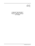
Refer to figure 1 for a typical schematic of the network and for the pin
outs of the network interface connectors. When wiring the network,
the following rules must be followed:
1) Wire the network using Belden #9182 single-shielded twisted pair
cable or an equivalent data communications cable meeting the
following spec:
Wire gauge: 22AWG
Nom. impedance: 150 ohms/ft.
Nom. attenuation at 1 MHZ: .004 db/ft.
Twisted pair, single-shielded
2) The total wire length of the network cannot exceed 1,000 ft. if
344KBPS is selected, 2,000 ft. at 229KBPS, and 4,000 ft. at
106KBPS.
3) The shield of the cable should be carried through the entire
network, using the shield tie points on the interface connectors to
achieve this. The shield tie-points on the connectors are not
internally tied to anything, they are strictly tie-points. One of
these tie-points should then be tied to earth ground.
4) The two extreme ends of the network should be terminated with
150 ohm resistors as shown in figure 1.
5) The network wiring should be isolated from other high voltage
wiring by routing the network in a separate conduit dedicated to
the network.
S3016-505 User’s Manual
SYSTEMS Electronics Group
-8-
SECTION 2
INSTALLATION
Figure 2.1 – Typical Network Wiring
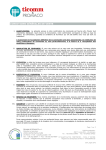
Figure 2.2 – Alternative Serial Connector Wiring
S3016-505 User’s Manual
SYSTEMS Electronics Group
-9-
SECTION 2
INSTALLATION
6) The network should be wired directly to the network comm port
connectors. No intermediate terminations or splices should be
used. The network should be wired in direct connect topology as
shown, not in multi-drop or cluster topologies.
Note: The network comm interface connectors contain two sets
of + and - terminals. The two sets of terminals are tied together
internally on the board (+ to +, - to -) and are provided as tiepoints to ease wiring. Communications across the network will
continue even if one of the nodes has failed provided all the
connectors are installed in their respective board. However, if a
connector is pulled from it's board, communications to the boards
downstream will be lost (the internal tie-point will be broken). If
it is desired, this situation can be avoided by wiring the
connectors as shown in figure 2.
________________________________________________________
2.2.2 SETTING THE NETWORK ADDRESSES IN THE
S3000/M4000 NODES
When using the "MCOM505" program, the network address of the
S3016-505 is automatically set to address 1. For this reason the
S3016-505 network address does not have to be set by the user. Each
of the slave S3000/M4000 nodes on the network must, however, be
set by the user with a unique network address between 2 and 32. This
is how the S3016-505 can distinguish one node from another. To set
the network address of a particular S3000/M4000 node, perform the
following:
1) Connect the IBM PC or compatible running SYSdev from the
"COM" port on the PC to the "PROG PORT" on the respective
S3000/M4000 node using an RS-232 cable.
2) From the SYSdev shell, select the program that is running in the
respective S3000/M4000 node.
3) From the SYSdev Main Development Menu, select "Target Board
Interface".
4) From the Target Board Interface menu, select "Target Board
Network Address".
S3016-505 User’s Manual
SYSTEMS Electronics Group
- 10 -
SECTION 2
INSTALLATION
5) SYSdev will read the current network address of the
S3000/M4000 node and display it in the network display. If the
network address is to be changed, follow the directions displayed
and enter the new address.
The steps above must be done for all S3000/M4000 nodes on the
network. This is true when the network is first installed, and when a
new S3000/M4000 node is added or replaced on the network (that
node must have the network address set in it).
________________________________________________________
2.3 I/O CONFIGURATION OF TI PROCESSORS
FOR S3016-505
The S3016-505 can be installed in any I/O slot of the TI 505 rack.
The S3016-505 is configured as a 3 word in/5 word out Special
Function module. In the TI I/O module definition table the S3016-505
should be defined as shown below:
Slot
I/O
Address
XX
XXXX
Number of BIT and WORD I/O
X
Y WX WY
00
00
03
05
Special
Function
YES
Where XX and XXXX under "SLOT" and "I/O ADDRESS" are the
user defined slots and I/O addresses where the S3016-505 is located.
S3016-505 User’s Manual
SYSTEMS Electronics Group
- 11 -
SECTION 2
INSTALLATION
________________________________________________________
2.4 DOWNLOADING “MCOM505” TO THE S3016-505
With the S3016-505 powered up, perform the following to download
the "MCOM505" program to the S3016-505:
1) Power up computer (PC) and invoke SYSdev from the root
directory of the hard drive by typing SYSdev<ENTER>. From the
SYSdev shell, select the directory that "MCOM505" is located in
by pressing "F3:Select Dir" and positioning the arrow at the
directory and pressing <ENTER>.
Note: If "MCOM505" has not yet been loaded onto the hard
drive of the computer, perform the steps in section 2.2.1 to load
"MCOM505" onto the computer.
2) Select the "MCOM505" program by positioning the arrow at
"MCOM505" and then press <ENTER>.
3) Select "6: Target Board Interface" from the main development
menu.
4) Connect the RS-232 cable from the "COM" port on the PC
running SYSdev to the "PROG" port on the S3016-505.
5) Download program "MCOM505" to the S3016-505 using the "1:
Download Program to Target Board" menu selection from the
"Target Board Interface Menu". The current address being
download will be displayed while the download is in progress.
6) Exit back from the "Target Board Interface" menu by pressing
12<ENTER>. Exit back to the SYSdev shell by again pressing
12<ENTER>. Exit back to the DOS prompt by selecting <ESC>.
S3016-505 User’s Manual
SYSTEMS Electronics Group
- 12 -
SECTION 2
INSTALLATION
________________________________________________________
2.4.1 INSTALLING “MCOM505” ON THE PC HARD DRIVE
To install "MCOM505" from the floppy disk to the hard drive on the
IBM PC or compatible running SYSdev, perform the following:
1) Power up computer (PC) and invoke SYSdev from the root
directory of the hard drive by typing SYSdev<ENTER>. From the
SYSdev shell, select the directory that "MCOM505" is to be
copied to by pressing "F3:Select Dir" and positioning the arrow at
the directory and pressing <ENTER>.
2) To enter "MCOM505" as a selection in the specified directory,
press "F1:Create Prog" then type "MCOM505" in the PROG field
of the SYSdev shell followed by <ENTER>. When the target
board type is prompted for, position the arrow by the S3016 and
press <ENTER>.
3) SYSdev will then prompt that the "MCOM505" does not exist,
create? (y/n). Answer "n" to this prompt.
4) SYSdev will return to the SYSdev shell with "MCOM505" now
entered in the shell directory.
5) Install the diskette that contains "MCOM505" in the "A" drive.
6) Position the arrow at "MCOM505" and press "F9:Restor Prog".
SYSdev will prompt for which drive to restore from. Answer "A"
and press <ENTER>.
7) "MCOM505" will be copied from the A drive to the directory on
the hard drive previously specified. "MCOM505" is now installed
on the hard drive.
Once the above steps are performed, "NETCOM" is used to define
what information (V memory locations, addresses in S3000/M4000
nodes, # of words to transfer, etc.) is transferred between the TI
processor and the various S3000/M4000 nodes. See section 3 for
details on using "NETCOM".
S3016-505 User’s Manual
SYSTEMS Electronics Group
- 13 -
SECTION 2
INSTALLATION
(This Page Intentionally Left Blank)
S3016-505 User’s Manual
SYSTEMS Electronics Group
- 14 -
SECTION 3
GENERAL DESCRIPTION OF “NETCOM”
"NETCOM" is a DOS based program used in conjunction with
"MCOM505" for the S3016-505. The combination of the
"MCOM505" and "NETCOM" programs turn the S3016-505 into a
purely communications board which allows the TI 505 processor to
communicate to up 31 S3000/M4000 slave nodes, reading up to 120
words and writing up to 120 words to each node. "NETCOM" allows
the user to perform the following:
1)
2)
3)
4)
Upload Node communication parameters from S3016-505.
Download Node communication parameters to S3016-505.
Save Node communication parameters in a file.
Document Nodes (S3000/M4000 network slave node
descriptions).
5) Print Node communication parameters / descriptions.
6) Create multiple network configuration files with up to 32
nodes per file.
The "NETCOM" program consists of a shell (first menu displayed
when "NETCOM" is invoked) plus the Main and Node Parameters
Edit menus used to select the various features of "NETCOM". The
shell is used for file and directory control. From this menu files,
which will store the node parameters, are created, copied, backed up
or restored. When a file is created or selected, the Main menu is then
invoked. From here the user edits the node parameters, downloads,
uploads, prints the parameters, etc. The following sections describe
all the menus and features of "NETCOM".
S3016-505 User’s Manual
SYSTEMS Electronics Group
- 15 -
SECTION 3
GENERAL DESCRIPTION OF “NETCOM”
________________________________________________________
3.1 INSTALLING AND RUNNING “NETCOM”
To install the program on your computer, load the diskette into drive
A, switch to the root directory of the hard drive you want to install it
on and type "A:INSTALL". The install program will create a
directory call "HSLSETUP" and copy the "NETCOM.EXE" program
to this directory.
To execute the "NETCOM" program, change to the "HSLSETUP"
directory and type NETCOM<ENTER>. The program will be
invoked and the "NETCOM" shell will be displayed. The following
sections describe this menu along with the other menus available in
"NETCOM".
If desired, the "NETCOM" shell can be bypassed by including the
path (directory) and file name on the command line when
"NETCOM" is invoked from the DOS prompt. This is usually done
when a menu program is used to select various software packages on
the users PC. This allows a specific file to be automatically invoked
from the user's menu program without having to go through the
"NETCOM" shell for file selection. The format of this is as follows:
HSLSETUP>NETCOM path filename<ENTER>
Where "path" is the directory\sub-directories that the file name is
under and "filename" is file that contains the respective node
parameters.
Note: There must be a space between "NETCOM" and "path" and a
space between "path" and "filename" in the above command line. No
extension is appended to "filename" in this command line as well.
An example of this is: HSLSETUP>NETCOM \NETWORK NET1
Where "NETWORK" is a directory off the root of the current drive
that contains a file named "NET1".
Note: Only an existing file can be accessed when adding the path
and filename to the command line. New files must be created through
the "NETCOM" shell by invoking "NETCOM" with no path and
filename specified.
S3016-505 User’s Manual
SYSTEMS Electronics Group
- 16 -
SECTION 3
GENERAL DESCRIPTION OF “NETCOM”
________________________________________________________
3.2 “NETCOM” SHELL
The “NETCOM” shell is used to organize the user directories, create
and edit user files, and automatically invoke the main menu when a
file is created or selected. Sub-directories should be used to store and
organize the user files. This is desirable both from the standpoint of
better user file management and from the standpoint of program
execution speed. The more files located in one directory, the slower
the access time to the sure files will be. Thus, by storing user files in
different directories that have a logical meaning to the user, and thus a
better file organization, the speed of execution of the “NETCOM”
program is also enhanced. The maximum number of files allowed in
one directory is 30. The maximum number of sub-directories in one
directory is 120. Of course by making sub-directories within subdirectories, no actual limit is placed on the number of user files which
can be stored on one hard drive (other than the actual amount of
memory on the hard drive). These sub-directories can be created
using the “F5: Make Dir” command in the “NETCOM” shell.
________________________________________________________
3.2.1 “NETCOM” SHELL MENU
The “NETCOM” shell consists of a menu which displays the selected
file name, current directory, target board along with fields that display
the existing file selections available for editing and available
directories. The definitions of these fields are as follows:
PROMPT:
This is a field which displays various prompts to
the user based on the selected command, informing
the user what to do.
DIR:
This field displays the currently selected drive and
directory. This is used as the path to the user file
name when creating or editing a file and is set
using the “F6: Select Drive: and “F3: Select Dir”
commands. When “NETCOM” is initially
invoked, this is set to the root directory of the
current drive.
S3016-505 User’s Manual
SYSTEMS Electronics Group
- 17 -
SECTION 3
GENERAL DESCRIPTION OF “NETCOM”
FILE:
FILE
SELECTIONS:
This is the file currently pointed to by the selection
arrow in the File Selections field of the menu. This
field is also used to enter the name of the user file
when the “F1: Create File” command is executed.
This field contains a list of the existing user files in
the currently selected directory. The currently
selected file is the file pointed to by the selection
arrow. The selection arrow can be moved to any
displayed file using the Left, Right, Up and Down
arrow keys. When “NETCOM” is initially
invoked, this displays all the “NETCOM” user files
in the root directory of the current drive.
SUB-DIRECTORY
SELECTIONS: This field contains a list of the existing subdirectories in the currently selected directory (these
would be sub-directories within the parent
directory). The “F3: Select Dir” command is used
to select one of these directories as the current
directory. When initially invoked, this displays all
the sub-directories in the root of the current drive
(whether they contain “NETCOM” user files or
not).
________________________________________________________
3.2.2 “NETCOM” SHELL COMMANDS
The shell contains numerous commands for creating and editing the
user file, selecting the directory and drive the user files are stored in,
and execution DOS commands such as Backup, Copy, Delete, etc.
from within the shell. The definitions of these commands are as
follows:
F1:
Create File
This command is used to create a new user file. When selected, the
menu will prompt for the file name. Enter the new name in the
“FILE:” filed of the menu using the valid MS-DOS file name
character set
S3016-505 User’s Manual
SYSTEMS Electronics Group
- 18 -
SECTION 3
GENERAL DESCRIPTION OF “NETCOM”
F2:
Set Colors
This selection allows the user to select the foreground color
(characters) and background color on PC’s equipped with color
monitors. Any of 16 foreground colors can be selected and any of 8
background colors.
F3:
Select Dir
This is used, to select, as the current directory, one of the directories
available in the sub-directories menu.
Note: Only directories within the current dub-directory are displayed
and are available for selection.
Pressing “F3” positions the selection arrow in the sub-directories
menu. Position the selection arrow at the desired sub-directory and
press ENTER. The “DIR:” field will be updated to show the newly
selected directory while the file selections menu will be updated to
show the existing user files in the selected directory. The subdirectories menu will also show the sub-directories that exist in the
selected directory.
Note: The “F4: Root Dir” command must be used to back out of the
currently selected directory and return to the root directory of the
currently selected drive.
F4:
Root Dir
Used to set “DIR:” to the root directory of the selected drive. This
command is primarily used to back out of the previously selected
directories if it is desired to charge to a directory that is not a subdirectory of the current directory. Pressing “F4” will set “DIR:” to
the root directory and display the user files and directories in the root
directory of the selected drive.
F5:
Make Dir
This selection creates a new sub-directory in the currently selected
directory. When selected, the menu will prompt for the directory
name. Enter the new name using the valid MS-DOS directory name
character set. The directory name can be a maximum of eight
characters in length. Press ENTER to accept the directory name. The
new directory will now be displayed in the sub-directories selection
menu and can now be selected as the current directory using the “F3:
Select Dir” command if desired.
S3016-505 User’s Manual
SYSTEMS Electronics Group
- 19 -
SECTION 3
GENERAL DESCRIPTION OF “NETCOM”
F6:
Select Drive
This selection is used to change the currently selected drive. When
selected, the shell prompts for the drive letter (A – Z). Enter the new
drive and press ENTER. The “DIR:” field will be changed to the root
directory of the new drive and the existing “NETCOM” user files and
sub-directories in the new drive root directory will be displayed.
F7:
Copy File
Used to copy the selected file to a new file name in the current
directory. Enter the new name using the valid MS-DOS file name
character set. The file name can be a maximum of eight characters in
length (no extension should be entered). Press ENTER to accept the
file name that the selected file will be copied to. The new file will
then be displayed in the file selections menu.
F8: Backup File
This selection is used to backup the selected file to the root directory
of a user specified diskette drive. When selected, the shell prompts
for the drive (A or B) that the file will be backed up to. Enter the
drive and press ENTER. The currently selected file will be copied to
the root directory of the specified diskette.
F9:
Restore File
This selection is used to restore a previously backed up file form the
root directory of a user specified drive to the currently selected
directory and file. When selected, the shell prompts for the diskette
drive (A or B) that the file will be copied from. Enter the drive and
press ENTER. The file, with the same name as the currently selected
program, will be copied from the root directory of the specified drive
to the currently selected directory and file name.
F10: Delete File
This section deletes the currently selected file from the current
directory. When selected, the shell prompts one time to verify that
the file is to be deleted, answer “Y” to delete, “N” to abort. If yes, the
file is deleted from the file selections menu.
S3016-505 User’s Manual
SYSTEMS Electronics Group
- 20 -
SECTION 3
GENERAL DESCRIPTION OF “NETCOM”
________________________________________________________
3.3 MAIN MENU
The Main menu is invoked after a new file is created from the shell or
when an existing file is selected from the shell or invoked from the
DOS command line.
Note: When a file is created for the first time, the "TI-505
Communications Status Stack address" menu is displayed first (see
section 3.3.5). This forces the user to set this address prior to editing
the rest of the communications parameters.
Once this is set, the Main menu is then displayed. The Main menu
allows the user to edit the node communications parameters,
download the node parameters to the S3016-505, upload the node
parameters from the S3016-505, print the node parameters, set the TI
505 status stack address, and monitor the communications status online. The following describes these menu selections.
________________________________________________________
3.3.1 EDIT NODE COMMUNICATIONS PARAMETERS
When this selection is made, the Node Parameters Edit menu is
invoked. This menu allows the user to select the node number, edit
the node description, edit the node communications parameters, and
enable or disable communications to the node. See section 3.4 for
complete details on these menu selections.
S3016-505 User’s Manual
SYSTEMS Electronics Group
- 21 -
SECTION 3
GENERAL DESCRIPTION OF “NETCOM”
________________________________________________________
3.3.2 DOWNLOAD PARAMETERS TO S3016-505
(PROG PORT)
This selection is used to download the node communications
parameters for the slave nodes to the S3016-505 from the computer.
Note: The node descriptions are not downloaded to the S3016-505,
these are saved in the file on disk only. The download feature allows
the user to either download all the nodes (2 to 32) or just a range of
nodes ("starting" node and "ending" node) as specified by the user.
This allows just a certain number of nodes (i.e. nodes 2 to 4) to be
downloaded without having to download all the parameters for all the
nodes.
To download the node parameters, connect an RS-232 cable from
COM1 on the computer to the "PROG" port on the S3016-505 and
press this selection. The user is then prompted to abort the download
(by pressing "ESC") or to continue (by pressing any other key). If any
key other than "ESC" is pressed, the following prompt is displayed:
"Download all nodes to S3016-505? (y/n): "
If all the parameters for all the nodes (2 to 32) are to be downloaded,
answer "y" to this prompt. If only a range of nodes is to be
downloaded, answer "n".
If "n" is answered, the user is then prompted for the starting node
number. Enter the starting node number to be downloaded and press
Enter. The user is then prompted for the ending node. Enter the
ending node number and press Enter. If, for instance, the parameters
for nodes 10 through 20 are to be downloaded, Enter 10 at the starting
node prompt and enter 20 at the ending node prompt.
In both cases, once the node download is initiated, the current node
number being downloaded is displayed on the computer.
Note: Communication on the S3000 network is halted while the
download is in progress. Communication between the TI processor
and S3016-505 is halted as well. Communication well automatically
resume to the slave nodes enabled as soon as the download is
complete.
S3016-505 User’s Manual
SYSTEMS Electronics Group
- 22 -
SECTION 3
GENERAL DESCRIPTION OF “NETCOM”
________________________________________________________
3.3.3 UPLOAD PARAMETERS FROM S3016-505
(PROG PORT)
This selection is used to upload the node communications parameters
for the slave nodes from the S3016-505 to the computer.
Note: The node descriptions are not uploaded from the S3016-505,
these are saved in the file on disk only. The upload feature allows the
user to either upload all the nodes (2 to 32) or just a range of nodes
("starting" node and "ending" node) as specified by the user. This
allows just a certain number of nodes (i.e. nodes 2 to 4) to be
uploaded without having to upload all the parameters for all the
nodes.
To upload the node parameters, connect an RS-232 cable from COM1
on the computer to the "PROG" port on the S3016-505 and press this
selection. The user is then prompted to abort the upload (by pressing
"ESC") or to continue (by pressing any other key). If any key other
than "ESC" is pressed, the following prompt is displayed:
"Upload all nodes from S3016-505? (y/n): "
If all the parameters for all the nodes (2 to 32) are to be uploaded,
answer "y" to this prompt. If only a range of nodes is to be uploaded,
answer "n".
If "n" is answered, the user is then prompted for the starting node
number. Enter the starting node number to be uploaded and press
Enter. The user is then prompted for the ending node. Enter the
ending node number and press Enter. If, for instance, the parameters
for nodes 10 through 20 are to be uploaded, Enter 10 at the starting
node prompt and enter 20 at the ending node prompt.
In both cases, once the node upload is initiated, the current node
number being uploaded is displayed on the computer.
Note: Communication on the S3000 network is halted while the
upload is in progress. Communication between the TI processor and
S3016-505 is halted as well. Communication well automatically
resume to the slave nodes enabled as soon as the upload is complete.
S3016-505 User’s Manual
SYSTEMS Electronics Group
- 23 -
SECTION 3
GENERAL DESCRIPTION OF “NETCOM”
________________________________________________________
3.3.4 PRINT NODE COMMUNICATIONS PARAMETERS
This selection is used to print the node communications parameters.
This selection prints all the information on the "Edit Node
Communications Parameters" menu: the node number, node
description, communications enabled/disabled, Words sent from TI505 to slave node, and Words read from slave node to TI-505. If
communications to a specific node is disabled, the Words sent and
read fields will not be printed. Similar to the download and upload,
the user can print the parameters for all the nodes (2-32) or just a
range of nodes.
When selected, the user will first be prompted for the form length.
This is the number of lines printed for each page and is typically 60.
Enter the number of lines per page and press Enter. Next the user is
prompted "Print-out parameters for all nodes (2 thru 32)? (y/n)".
Answering "y" will print the parameters for all the nodes (2 thru 32).
If "n" is answered the user is then prompted for the starting node
number to print. Enter the starting node number and press Enter. Next
the ending node number is prompted for. Enter the ending node
number and press enter. For instance, if nodes 10 thru 20 are to be
printed, enter 10 for the starting node and 20 for the ending node.
Once the above prompts are answered, the print-out will be initiated.
Pressing "ESC" at any of the prompts will abort the print-out
selection. Pressing any key once the print-out is initiated will abort
the print-out.
S3016-505 User’s Manual
SYSTEMS Electronics Group
- 24 -
SECTION 3
GENERAL DESCRIPTION OF “NETCOM”
________________________________________________________
3.3.5 SET TI-505 COMMUNICATIONS STATUS STACK
ADDRESS
The TI-505 Communications Status stack is 32 consecutive V
memory locations in the TI 505 processor which represent the
communications status of each node in the S3016-505.
The first V memory location is a watchdog toggle from the S3016505. This is toggled between 0 and 1 once all the enabled nodes are
updated in the S3016-505. This should be monitored for a change of
state by the TI-505 program to verify that the S3016-505 is
functioning. This is generally accomplished with a timer that is reset
by a one shot fired every time this V memory location changes from
either 0 to a 1 or a 1 to a 0.
Note: While the Node parameters are being downloaded to the
S3016-505, that this location will not change state. Thus the timer
should be set to the maximum download time (approximately 5
seconds).
The remainder of the V memory locations of this stack are the
communications status of the respective 31 slave nodes (the second V
memory location is for node 2, the third for node 3, etc.). The values
loaded into these locations by the S3016-505 are numbers between 0
and 19 decimal. These are the same status codes as displayed in the
"Communications Status" menu (selection 6 of the Main menu). See
section 3.3.6 for definitions of these codes. These status registers
should be monitored by the TI-505 program to verify that
communications to a specific node is occurring if that node is
enabled.
When this selection is made, the current TI-505 Communications
Status stack address is displayed. This is the first address of the stack.
To change this address, simply type in the desired V memory address
and press <ENTER>. If the address is not to be changed, press
<ESC>.
Note: This address is only loaded to the S3016-505 when the
"Download Parameters to S3016-505" selection is performed. If this
address is changed, the download must be performed to update the
S3016-505.
S3016-505 User’s Manual
SYSTEMS Electronics Group
- 25 -
SECTION 3
GENERAL DESCRIPTION OF “NETCOM”
________________________________________________________
3.3.6 MONITOR COMMUNICATIONS STATUS (PROG PORT)
This selections is used to monitor the communications status on-line.
The status of each node is displayed in a table with a status code and
short description of each code. These are the same status codes passed
to the TI-505 processor in the "TI-505 communications status stack"
(see section 3.3.5). The list of possible codes is shown below:
Code
(HEX)
00H
01H
02H
03H
04H
05H
06H
07H
08H
09H
0AH
0BH
0CH
0DH
0EH
0FH
10H
11H
12H
13H
Code
(decimal)
00
01
02
03
04
05
06
07
08
09
10
11
12
13
14
15
16
17
18
19
Definition
Comm to Node Disabled
-------Comm to Node OK
More than one bus master
Xmitt timeout - no response
No slave response - timeout
Invalid command from master
Receive overflow
Receive collision detected
Receive alignment error
Receive CRC error
Unknown error
Xmitt no acknowledge
Xmitt under run error
Xmitt collision detected
Address range error
Unexpected slave response
TI-505/S3016 read error
TI-505/S3016 write error
Undefined error
Status code 00H "Comm to Node Disabled" is set when
communications to the respective node is disabled (see section 3.4.4).
This is the normal status code for any unused nodes on the network.
Status code 02H "Comm to Node OK" is the normal status code when
a node is enabled for communications and communications to that
node is successful. Status codes 03H through 10H are network
communication error codes. In this case comm to the node was
enabled but communications to that node was not successful. The data
returned to the TI-505 processor for that node would not be valid.
These error codes are serial network error codes listed in the S3016
User's Manual. Refer to that manual for a complete description of
these error codes.
S3016-505 User’s Manual
SYSTEMS Electronics Group
- 26 -
SECTION 3
GENERAL DESCRIPTION OF “NETCOM”
To view the communications status, connect an RS-232 cable from
COM1 on the computer to the "PROG" port on the S3016-505 and
press this selection. The status of each node will then be displayed in
the status table.
Note: This table is updated continuously such that any change in the
communications status of any node is reflected in the table
immediately. If the RS-232 communications from the computer to the
S3016-505 cannot be established (cable not connected, etc.), the
status table will display "---: ------------" for each node in the table.
This indicates that the computer is not communicating to the S3016505.
________________________________________________________
3.4 NODE PARAMETERS EDIT MENU
The Node Parameters Edit menu is used to define the communications
parameters of each node as well as enable or disable communications
to the node and enter descriptions for each node. The following
selections are available on this menu:
1:
2:
3:
4:
Select Node number
Edit Node description
Edit Node Communications Parameters
Enable/Disable Communications to Node
In addition to the above selections, this menu contains the following
fields:
Node Number: Currently selected node for edit of description and
communication parameters.
Node Description: User entered description of the node (type of
machine, type of S3000/M4000 processor, etc., whatever is
desired by the user to describe the node up to 50 characters).
S3016-505 User’s Manual
SYSTEMS Electronics Group
- 27 -
SECTION 3
GENERAL DESCRIPTION OF “NETCOM”
Communications to Node: Enabled/Disabled -This field
indicates whether communications to the node is enabled or
disabled. When enabled, the S3016-505 communicates to the
respective node using the parameters defined for that node
(number of words, addresses to transfer, etc.). This information is
then communicated to the TI processor. When disabled, no
communications is performed to the respective node and no
information is transferred to the TI processor. The communication
parameter fields are blanked as well when comm is disabled.
Words sent from TI-505 to Slave Node: The following three
fields are the communication parameters which define the words
sent from the TI-505 to the slave node:
# of Words to send from TI-505 to slave node: This is the
number of V memory words that will be transmitted to the slave
node. This is a decimal value between 0 and 120.
Starting address in TI-505 of words to send: First address
of send stack in TI-505 processor. A consecutive number of V
memory variables (equal to # of Words to send) will be sent to the
respective slave node starting at this address. Valid variable type
is V memory only within the V memory space of the TI 505
processor.
Starting address in slave node to store words at: First
address of stack in slave node (S3000/M4000 processor) where
the words sent from the master will be stored. This is either a 'W'
word address of an external hex address in the slave node
processor (see respective user's manual for slave node processor
for valid 'W' addresses and external memory addresses).
S3016-505 User’s Manual
SYSTEMS Electronics Group
- 28 -
SECTION 3
GENERAL DESCRIPTION OF “NETCOM”
Words read from slave node to TI-505: The following three
fields are the communication parameters which define the words
read from the slave node and stored in the TI-505 processor:
# of Words to read from slave node to TI-505: This is the
number words that will be read from the slave node and stored in
V memory locations of the TI-505 processor.
Starting address in slave node to read words from: This
is the starting address of the consecutive words in the slave node
processor that will be sent to the TI-505. This is either a 'W' word
address of an external hex address in the slave node processor (see
respective user's manual for slave node processor for valid 'W'
addresses and external memory addresses).
Starting address in TI-505 to store words at: First address
of consecutive V memory locations in TI-505 processor that
words read from the slave node will be stored. Valid variable type
is V memory only within the V memory space of the TI 505
processor.
The following section describes each of the selections in the Node
Parameters Edit menu:
________________________________________________________
3.4.1 SELECT NODE NUMBER
This selection is used to select the slave node number for editing the
node description, enabling or disabling communications to the node,
and setting the communication parameters for the slave node. When
selected, enter the node number (2 through 32) to be edited and press
<ENTER>. In addition the next or previous node can be selected by
pressing the "PgDn" or "PgUp" keys respectively.
S3016-505 User’s Manual
SYSTEMS Electronics Group
- 29 -
SECTION 3
GENERAL DESCRIPTION OF “NETCOM”
________________________________________________________
3.4.2 EDIT NODE DESCRIPTION
This selection is used to edit the "Node Description" field of the
currently selected slave node. This field can be used to describe the
slave node (type of machine, type of S3000/M4000 processor, etc.).
When selected, the cursor is placed at the beginning of this field.
Enter the desired node description (up to 50 characters) and press
<ENTER>.
________________________________________________________
3.4.3 EDIT NODE COMMUNICATIONS PARAMETERS
This selection is used to modify the communication parameters of the
currently selected node. This includes: "# of Words to send from TI505 to slave node", "Starting address in TI-505 of words to send",
"Starting address in slave node to store words at", "# of Words to read
from slave node to TI-505", "Starting address in slave node to read
words from", and "Starting address in TI-505 to store words at".
If the node is not already enabled for communications when this
selection is made, the user is prompted to enable communications. If
communications is to be enabled, answer "y", if not, answer "n". If
communications is not enabled, the communication parameters cannot
be set and the cursor will return to the Enter selection prompt.
If communications is enabled, the cursor will be located in the "# of
Words to send" field. Enter the number of words to be sent and press
<ENTER>. The cursor will move to the "Starting address in TI-505"
field. Enter the starting V memory address of the send stack (the "V"
is automatically prefixed to the beginning of the address) and press
<ENTER>. The cursor will now move to the "Starting address in the
slave node" field. Enter the starting address in the slave that the words
sent will be stored at as either a valid "W" address in the form
"Wxxxx" where xxxx is the address or as a valid external memory
hex address in the form "xxxxH" where xxxx is the hex address and
press <ENTER>. The above three fields were the "Words sent from
TI-505 to slave node" communications parameters. The cursor will
now advance to the three fields of the "Words read from slave node to
TI-505". Enter these in the same way that the three previous fields
were entered.
S3016-505 User’s Manual
SYSTEMS Electronics Group
- 30 -
SECTION 3
GENERAL DESCRIPTION OF “NETCOM”
________________________________________________________
3.4.4 ENABLE/DISABLE COMMUNICATIONS TO NODE
This selection is used to enable or disable communications to the
currently selected node. When the node file is first created, by default,
communications to all nodes is disabled. The user then enables
communications only to the respective nodes that are connected to the
network. For instance, if the S3016-505 is connected to only one
other S3000/M4000 slave node, communications to that node only
should be enabled, all other nodes should be disabled. If the S3016505 is connected to two slave nodes, communications to those two
nodes should be enabled, and all other nodes disabled and so on.
This selection simply toggles the enable or disable state of the node.
If the node is disabled, pressing "4: Enable/Disable" will enable the
node. If the node is disabled, pressing "4: Enable/Disable" will
disable the node.
Note: When the node is enabled, the communication parameters
values are shown in the parameter fields. When disabled, the fields
are blanked, even though the parameter values in those fields are still
retained in memory and are shown when the communications is
enabled again.
Also, that when any of the descriptions or parameters are modified for
any of the nodes, the data is saved in the currently selected file when
the "Node Parameters Edit" menu is exited. Also the S3016-505 is not
updated with any changes until the "Download Parameters" is
performed to the S3016-505.
S3016-505 User’s Manual
SYSTEMS Electronics Group
- 31 -
SECTION 3
GENERAL DESCRIPTION OF “NETCOM”
(This Page Intentionally Left Blank)
S3016-505 User’s Manual
SYSTEMS Electronics Group
- 32 -
SECTION 4
SPECIFICATIONS
Board Size:
Length:
Height:
Width:
9.15"
6.30"
0.80"
Processor Memory:
Program:
Data:
non-volatile:
volatile:
Flags (F):
Bytes (B):
Words (W):
Interface Ports:
PROG PORT:
Type:
Comm Rate:
USER PORT:
Type:
Comm Rate:
Start bits:
Data bits:
Stop bits:
Parity:
Serial Network:
S3000-N1:
Type:
Comm Rate:
# of nodes (max):
Isolation:
Distance:
Protocol:
Power Requirements:
Icc (+5VDC):
S3016-505 User’s Manual
24K bytes battery backed
CMOS RAM
2K bytes battery backed CMOS
RAM
104 bits
185 bytes
93 words
RS-232
9600 BAUD
RS-232/RS-422
300,600,1200,2400,4800,9600
BAUD
1
8
1 or 2
NONE, ODD, or EVEN
RS-485
344KBPS, 229KBPS, or
106KBPS
32
2000 VRMS
1000 ft., 2000 ft., or 4000ft.
Proprietary
1.00 amps (MAX)
SYSTEMS Electronics Group
- 33 -
SECTION 4
SPECIFICATIONS
Temperature Range:
Storage:
Operating:
0 to 70 degrees C
0 to 60 degrees C
Relative Humidity:
5 to 95% (non-condensing)
S3016-505 User’s Manual
SYSTEMS Electronics Group
- 34 -
APPENDIX A
MCOM505 PROGRAM PRINTOUT
S3016-505 S3000 Network Master (31 slave nodes)
SYS51 System Config: C:\PROGRAMS\S3016505\MCOM505.LCF
System Configuration
-------------------Target board: S3016 Communications co-processor I/O board
Network baud rate: 344KBPS
USER PORT baud rate: 9600
USER PORT parity: NONE
USER PORT stop bits: 1
Co-cpu communications interrupt enabled: no
S3016-505 User’s Manual
SYSTEMS Electronics Group
- A-1 -
APPENDIX A
MCOM505 PROGRAM PRINTOUT
S3016-505 S3000 Network Master (31 slave nodes)
SYS51 Init file: C:\PROGRAMS\S3016505\MCOM505.LIN
03/11/02
Page:
1
**************************************************************************
block: 1 - High-level
0:sfunc07(1900H,B90);
1:sfunc07(1901H,B91);
2:
3:sfunc08(1ff4H,1);
4:B105 = 2;
5:F10 = 0;
6:
F010
B090
B091
B105
(TIreset)
(Verrstk)
(Verrstk)
(dwnload)
TI505
Vmem
Vmem
down-
/* restore TI-505 com stack address */
/* set node address to 1 (master) */
/* start in download mode until TI545 resets */
/* TI505 resetting */
reset
error
error
load
comp
stack
stack
mode
S3016-505 User’s Manual
SYSTEMS Electronics Group
- A-2 -
APPENDIX A
MCOM505 PROGRAM PRINTOUT
S3016-505 S3000 Network Master (31 slave nodes)
SYS51 Init file: C:\PROGRAMS\S3016505\MCOM505.LIN
03/11/02
Page:
2
**************************************************************************
block: 2 - Assembly
0:
1:
clr
EX1
;disable comm interrupt from TI505
S3016-505 User’s Manual
SYSTEMS Electronics Group
- A-3 -
APPENDIX A
MCOM505 PROGRAM PRINTOUT
S3016-505 S3000 Network Master (31 slave nodes)
SYS51 Main Program: C:\PROGRAMS\S3016505\MCOM505.LMN
03/11/02
Page:
1
**************************************************************************
block: 1 - High-level
** Select state **
This block searches for enabled slave nodes (1st address of respective
slave buffer set to the slave number when enabled) and then initiates
the comm cycle with the TI545. The data is read from the TI545 and
stored in the slave xmit buffer and then the data in the slave rcve
buffer is written to the TI545. Once all slave nodes (2-32) have been
updated, the network comm (sfunc13) error stack is written to the
TI545.
0:if
1:
2:
3:
4:
5:
6:
7:
8:
9:
10:
11:
12:
13:
14:
15:
16:
17:
18:
19:
20:
21:
22:
23:
24:
25:
26:
27:
28:
29:
30:
31:
32:
33:
34:
35:
36:
37:
38:
39:
40:
(F0 == 1)
/* select state? */
{
F8 = 0;
/* reset done bit */
for (B42 = B61 + 1; B42 < 33 && F8 == 0; ++B42)
{
/* search for enabled slave nodes and comm with TI545 */
W84 = (B42*512)+3c00H;
/* point to nth node */
sfunc07(W84,B87);
if (B87 == B42)
/* slave node enabled? */
{
W84 = W84 + 2;
/* load comm parameters */
sfunc07(W84,B62);
/* # to send */
W84 = W84 + 2;
sfunc07(W84,B64); ++W84; /* VSRCE address */
sfunc07(W84,B65); ++W84;
sfunc07(W84,B66); ++W84; /* sdest address */
sfunc07(W84,B67); ++W84;
sfunc07(W84,B63); ++W84; /* # to receive */
++W84;
sfunc07(W84,B68); ++W84; /* ssrce address */
sfunc07(W84,B69); ++W84;
sfunc07(W84,B70); ++W84; /* VDEST address */
sfunc07(W84,B71);
}
W84 = W84 + 3;
B61 = B42;
F8 = 1;
}
if (F8 == 0)
{
B61 = 1;
B63 = 32;
W70 = W90;
W84 = 1b00H;
sfunc07(1b00H,B87);
B87.0 = ~B87.0;
sfunc08(1b00H,B87);
F4 = 1;
}
/* point to xmit buffer */
/* set slave address */
/* done */
/* all nodes checked? */
/*
/*
/*
/*
/*
start with first slave node again */
write comm error status to TI545 */
VDEST = VERROR_STACK */
point to comm error stack */
toggle S3016-505 (TI545) watchdog */
/* write comm error status */
S3016-505 User’s Manual
SYSTEMS Electronics Group
- A-4 -
APPENDIX A
MCOM505 PROGRAM PRINTOUT
- block continued on next page -
S3016-505 User’s Manual
SYSTEMS Electronics Group
- A-5 -
APPENDIX A
MCOM505 PROGRAM PRINTOUT
S3016-505 S3000 Network Master (31 slave nodes)
SYS51 Main Program: C:\PROGRAMS\S3016505\MCOM505.LMN
block:
03/11/02
Page:
2
1 - High-level
- block originated on prev page 41:
else
42:
F1 = 1;
43:
}
44:
45:F0 = 0;
46:
F000 (select )
F001 (read TI)
F004 (writeTI)
F008 ( done )
B042 ( (i) )
B061 ( slave )
B062 ( #send )
B063 ( #rcve )
B064 ( Vsrce )
B065 ( Vsrce )
B066 ( sdest )
B067 ( sdest )
B068 ( ssrce )
B069 ( ssrce )
B070 ( Vdest )
B071 ( Vdest )
B087 (tempreg)
B087.0(tregbt0)
W070 ( Vdest )
W084 (slveptr)
W090 (Verrstk)
select
read
write
/* initiate read state */
/* exit select state */
slave
TI545
TI545
state
state
state
done
loop
(i)
network slave
number
# of
words to send
# of
words to rcve
Vmem
source address
Vmem
source address
slave
dest
address
slave
dest
address
slave source address
slave source address
Vmem
dest
address
Vmem
dest
address
temp
registr
temp
reg
bit0
Vmem
dest
address
slave
buffer pointer
Vmem
error
stack
S3016-505 User’s Manual
SYSTEMS Electronics Group
- A-6 -
APPENDIX A
MCOM505 PROGRAM PRINTOUT
S3016-505 S3000 Network Master (31 slave nodes)
SYS51 Main Program: C:\PROGRAMS\S3016505\MCOM505.LMN
03/11/02
Page:
3
**************************************************************************
block: 2 - High-level
** Read state **
The next two blocks perform the first step of the communication cycle to
the currently selected slave (read TI-545). In this state, the TI-545
V-memory is read (the number of words specified in "#sent" starting
at "Vsrce") and loaded into the respective slave xmit buffer
(addresses 4000H to 7c00H). This is the data that will be sent to
the respective slave node.
0:if
1:
2:
3:
4:
5:
6:
7:
8:
9:
10:
11:
12:
13:
14:
15:
F001
F002
B035
B039
B062
B086
B182
W036
W064
W088
(F1 == 1)
/* read state? */
{
if (F2 == 0)
/* read from 545 not yet initiated? */
{
B86 = &B182;
/* initiate pointer to task code read buffer */
W88 = 1a00H;
/* initiate pointer to TI545 buffer */
if (B62%15 == 0) /* even number of 15 word blocks to read? */
B35 = B62/15; /* yes, calc # of blocks to read */
else
B35 = B62/15 + 1;
/* calc # of blocks to read */
W36 = W64-1;
/* initiate Vaddr in 545 to read from */
F2 = 1;
/* read initiated */
B39 = 6;
/* max number of error retries = 6 */
}
}
(read TI)
(rd init)
(numblks)
(err cnt)
( #send )
( pntr1 )
( rbuff )
( Vaddr )
( Vsrce )
( pntr2 )
read
read
# of
TI task
# of
task
tskcode
TI545
Vmem
network
TI545
state
blocks
retry
words
buffer
read
Vmem
source
buffer
state
initiat
TI task
count
to send
pointer
buffer
address
address
pointer
S3016-505 User’s Manual
SYSTEMS Electronics Group
- A-7 -
APPENDIX A
MCOM505 PROGRAM PRINTOUT
S3016-505 S3000 Network Master (31 slave nodes)
SYS51 Main Program: C:\PROGRAMS\S3016505\MCOM505.LMN
03/11/02
Page:
4
**************************************************************************
block: 3 - High-level
0:if (F1 == 1)
/* read state? */
1:
{
2:
if (F103 == 0)
/* task code with 545 complete? */
3:
{
/* yes */
4:
if (F102 == 1)
/* task code comm failure with 545? */
5:
{
6:
--B39;
/* dec error count */
7:
if (B39 == 0) /* error retries count out? */
8:
{
9:
B40 = 11H; /* comm error = TI_READ_ERROR */
10:
W106 = 1b00H + ((B61-1)<<1);
11:
sfunc08(W106,B40); ++W106; /* save fault code in */
12:
sfunc08(W106,0);
/* TI-505 comm stat stack */
13:
F1 = 0, F2 = 0, F0 = 1;
/* exit read state */
14:
}
15:
else
16:
F103 = 1;
/* retry task code comm with 545 */
17:
F102 = 0;
/* reset task code comm fail bit */
18:
}
19:
else if (F9 == 1) /* task code comm done? */
20:
{
21:
for (B42 = 0; B42 < 15; ++B42)
/* copy block read from 545 */
22:
{
/* to network xmit buffer */
23:
sfunc08(W88,*B86); ++B86, ++W88;
/* copy nth word */
24:
sfunc08(W88,*B86); ++B86, ++W88;
25:
}
26:
B86 = &B182;
/* reset task code read buffer */
27:
F9 = 0;
/* block read done */
28:
}
29:
else if (B35 != 0)
/* more blocks to read? */
30:
{
31:
B56 = 50H;
/* block read task code */
32:
B57 = 4;
/* # of bytes to xmit in task code req */
33:
B58 = 32;
/* # of bytes to rcve in task code resp */
34:
W150 = W36;
/* starting V mem address to read */
35:
W36 = W36 + 15;
/* next block address to read */
36:
--B35;
/* dec # of blocks to read */
37:
F103 = 1;
/* initiate task code comm */
38:
F9 = 1;
/* preset block read done */
39:
}
40:
else
41:
{
42:
W88 = 1a00H;
/* copy data read from TI545 to */
43:
while (B62 != 0)
/* respective slave xmit buffer */
44:
{
45:
sfunc07(W88,B87);
46:
sfunc08(W84,B87); ++W84, ++W88;
47:
sfunc07(W88,B87);
48:
sfunc08(W84,B87); ++W84, ++W88;
49:
--B62;
50:
}
S3016-505 User’s Manual
SYSTEMS Electronics Group
- A-8 -
APPENDIX A
MCOM505 PROGRAM PRINTOUT
- block continued on next page -
S3016-505 User’s Manual
SYSTEMS Electronics Group
- A-9 -
APPENDIX A
MCOM505 PROGRAM PRINTOUT
S3016-505 S3000 Network Master (31 slave nodes)
SYS51 Main Program: C:\PROGRAMS\S3016505\MCOM505.LMN
block:
03/11/02
Page:
5
3 - High-level
- block originated on prev page 51:
52:
53:
54:
55:
56:
F000
F001
F002
F004
F009
F102
F103
B035
B039
B040
B042
B056
B057
B058
B061
B062
B086
B087
B182
W036
W084
W088
W106
W150
}
}
F1 = 0, F2 = 0, F4 = 1;
/* enter write state */
W84 = (B61*512)+3c00H+256; /* point to respective rcve buffer */
}
(select )
(read TI)
(rd init)
(writeTI)
(TI done)
(tskfail)
(TIcomm )
(numblks)
(err cnt)
(commerr)
( (i) )
(tskcode)
(#xmitt )
( #rcve )
( slave )
( #send )
( pntr1 )
(tempreg)
( rbuff )
( Vaddr )
(slveptr)
( pntr2 )
(statptr)
(Vstack )
select slave
read
TI545
read
state
write
TI545
TI545
task
TI545
task
TI545
task
# of
blocks
TI task retry
comm
error
loop
TI545
task
task
code
task
code
network slave
# of
words
task
buffer
temp
tskcode read
TI545
Vmem
slave
buffer
network buffer
comm
status
Vmem
read
state
state
initiat
state
done
fail
in prog
TI task
count
code
(i)
code
#xmitt
#rcve
number
to send
pointer
registr
buffer
address
pointer
pointer
pointer
stack
S3016-505 User’s Manual
SYSTEMS Electronics Group
- A-10 -
APPENDIX A
MCOM505 PROGRAM PRINTOUT
S3016-505 S3000 Network Master (31 slave nodes)
SYS51 Main Program: C:\PROGRAMS\S3016505\MCOM505.LMN
03/11/02
Page:
6
**************************************************************************
block: 4 - High-level
** Write state **
The next two blocks write the data that was read from the slave to the
TI-545 Vmemory starting at "Vdest" (the number of words written is
"#rcve").
0:if
1:
2:
3:
4:
5:
6:
7:
8:
9:
10:
11:
12:
13:
14:
15:
16:
17:
18:
19:
20:
21:
22:
23:
24:
25:
26:
27:
28:
29:
F004
F005
B035
B039
B042
B043
B061
B063
B086
B087
B108
B152
W036
(F4 ==
{
if (F5
{
W88
for
1)
/* write state? */
== 0)
/* write state not yet initiated? */
= 1a00H;
/* copy data to be written to TI545 from */
(B42 = B63; B42 > 0; --B42) /* respective slave rcve buffer */
{
sfunc07(W84,B87);
sfunc08(W88,B87);
++W84, ++W88;
sfunc07(W84,B87);
sfunc08(W88,B87);
++W84, ++W88;
}
B86 = &B152;
/* initiate pointer to task code write buffer */
W88 = 1a00H;
/* initiate pointer to TI545 buffer */
B35 = B63/14;
/* number of blocks to write */
B43 = B63%14;
/* number of words remaining to write */
W36 = W70-1;
/* initiate Vmem dest address */
F5 = 1;
/* write state initiated */
B39 = 6;
/* maximum # of error retries = 6 */
}
/* reset TI_READ_ERROR */
W106 = 1b00H + ((B61-1)<<1);
sfunc07(W106,B108);
if (B108 == 11H)
sfunc08(W106,2);
}
(writeTI)
(wr init)
(numblks)
(err cnt)
( (i) )
(#words )
( slave )
( #rcve )
( pntr1 )
(tempreg)
(comstat)
( xbuff )
( Vaddr )
write
TI545
write
state
# of
blocks
TI task retry
loop
# of
words
network slave
# of
words
task
buffer
temp
comm
tskcode write
TI545
Vmem
state
initiat
TI task
count
(i)
remain
number
to rcve
pointer
registr
status
buffer
address
S3016-505 User’s Manual
SYSTEMS Electronics Group
- A-11 -
APPENDIX A
MCOM505 PROGRAM PRINTOUT
W070
( Vdest )
Vmem
dest
address
S3016-505 User’s Manual
SYSTEMS Electronics Group
- A-12 -
APPENDIX A
MCOM505 PROGRAM PRINTOUT
S3016-505 S3000 Network Master (31 slave nodes)
SYS51 Main Program: C:\PROGRAMS\S3016505\MCOM505.LMN
block:
W084
W088
W106
03/11/02
Page:
7
4 - High-level
(slveptr)
( pntr2 )
(statptr)
slave
buffer pointer
network buffer pointer
comm
status pointer
S3016-505 User’s Manual
SYSTEMS Electronics Group
- A-13 -
APPENDIX A
MCOM505 PROGRAM PRINTOUT
S3016-505 S3000 Network Master (31 slave nodes)
SYS51 Main Program: C:\PROGRAMS\S3016505\MCOM505.LMN
03/11/02
Page:
8
**************************************************************************
block: 5 - High-level
0:if (F4 == 1)
/* write state? */
1:
{
2:
if (F103 == 0)
/* task code with TI 545 complete? */
3:
{
/* yes */
4:
if (F102 == 1)
/* task code comm failure with 545? */
5:
{
6:
--B39;
/* dec error count */
7:
if (B39 == 0) /* maximum number of retries done? */
8:
{
9:
B40 = 12H; /* comm error = TI_WRITE_ERROR */
10:
W106 = 1b00H + ((B61-1)<<1);
11:
sfunc08(W106,B40); ++W106;
/* save fault code in */
12:
sfunc08(W106,0);
/* TI-505 stat stack */
13:
F4 = 0, F5 = 0, F0 = 1; /* exit write state */
14:
}
15:
else
16:
F103 = 1;
/* retry task code with 545 */
17:
F102 = 0;
18:
}
19:
else if (B35 != 0)
/* more blocks to write? */
20:
{
21:
B56 = 51H;
/* block write task code */
22:
B57 = 32;
/* number of task code bytes to write */
23:
B58 = 2;
/* number of task code bytes to read */
24:
W150 = W36;
/* Vmem start address */
25:
W36 = W36 + 14;
/* next block start address to write */
26:
--B35;
/* dec # of blocks to write */
27:
B86 = &B152;
/* point to task code write buffer */
28:
for (B42 = 0; B42 < 14; ++B42)
29:
{
30:
sfunc07(W88,*B86); ++W88, ++B86; /* copy from comm buffer */
31:
sfunc07(W88,*B86); ++W88, ++B86; /* to task code buffer */
32:
}
33:
F103 = 1;
/* initiate tasck code comm with 545 */
34:
}
35:
else if (B43 != 0)
/* write remaining words to 545? */
36:
{
37:
B56 = 51H;
/* block write task code */
38:
B57 = (B43 << 1) + 4;
/* # of bytes to write */
39:
B58 = 2;
/* # of bytes to read in task code */
40:
W150 = W36;
/* Vmem start address */
41:
B86 = &B152;
/* point to task code write buffer */
42:
for (B42 = 0; B42 < B43; ++ B42)
43:
{
44:
sfunc07(W88,*B86);
/* copy nth word from comm buffer */
45:
++W88, ++B86;
/* to task code write buffer */
46:
sfunc07(W88,*B86);
47:
++W88, ++B86;
48:
}
49:
B43 = 0;
/* reset # remaining */
50:
F103 = 1;
/* initiate task code comm */
S3016-505 User’s Manual
SYSTEMS Electronics Group
- A-14 -
APPENDIX A
MCOM505 PROGRAM PRINTOUT
- block continued on next page -
S3016-505 User’s Manual
SYSTEMS Electronics Group
- A-15 -
APPENDIX A
MCOM505 PROGRAM PRINTOUT
S3016-505 S3000 Network Master (31 slave nodes)
SYS51 Main Program: C:\PROGRAMS\S3016505\MCOM505.LMN
block:
03/11/02
Page:
9
5 - High-level
- block originated on prev page 51:
52:
53:
54:
55:
56:
F000
F004
F005
F006
F102
F103
B035
B039
B040
B042
B043
B056
B057
B058
B061
B086
B152
W036
W088
W106
W150
}
}
else
F4 = 0, F5 = 0, F6 = 1;
}
(select )
(writeTI)
(wr init)
(comdone)
(tskfail)
(TIcomm )
(numblks)
(err cnt)
(commerr)
( (i) )
(#words )
(tskcode)
(#xmitt )
( #rcve )
( slave )
( pntr1 )
( xbuff )
( Vaddr )
( pntr2 )
(statptr)
(Vstack )
select slave
write
TI545
write
state
TI545
comm
TI545
task
TI545
task
# of
blocks
TI task retry
comm
error
loop
# of
words
TI545
task
task
code
task
code
network slave
task
buffer
tskcode write
TI545
Vmem
network buffer
comm
status
Vmem
read
/* enter done state */
state
state
initiat
done
fail
in prog
TI task
count
code
(i)
remain
code
#xmitt
#rcve
number
pointer
buffer
address
pointer
pointer
stack
S3016-505 User’s Manual
SYSTEMS Electronics Group
- A-16 -
APPENDIX A
MCOM505 PROGRAM PRINTOUT
S3016-505 S3000 Network Master (31 slave nodes)
SYS51 Main Program: C:\PROGRAMS\S3016505\MCOM505.LMN
03/11/02
Page: 10
**************************************************************************
block: 6 - High-level
** Comm network node select state **
This block searches for enabled nodes and initiates the parameters
and communications with any enabled nodes.
0:if
1:
2:
3:
4:
5:
6:
7:
8:
9:
10:
11:
12:
13:
14:
15:
16:
17:
18:
19:
20:
21:
22:
23:
24:
25:
26:
27:
28:
29:
30:
31:
32:
33:
34:
35:
36:
37:
38:
39:
40:
41:
42:
43:
44:
45:
(F3 == 0 && B105 == 0)
/* select comm node? */
{
F8 = 0;
/* reset done bit */
for (B42 = B96 + 1; B42 < 33 && F8 == 0; ++B42)
{
/* search for enabled nodes and initiate comm */
W92 = (B42*512)+3c00H;
/* point to nth node */
sfunc07(W92,B87);
if (B87 == B42)
/* nth node enabled? */
{
B96 = B42;
/* initiate comm with node */
F8 = 1;
}
else
{
W106 = 1b00H + ((B42-1)<<1);
sfunc08(W106,0); ++W106; /* set stat to "disabled" */
sfunc08(W106,0);
/* in TI-505 stat stack is not used */
}
}
if (F8 == 0)
/* all nodes checked? */
B96 = 1;
/* yes, start again with first slave */
else
{
W92 = W92 + 2;
/* get parameters for nth node */
sfunc07(W92,B97);
/* # to xmit */
W92 = W92+4;
sfunc07(W92,B66); ++W92; /* sdest */
sfunc07(W92,B67); ++W92;
sfunc07(W92,B98);
/* # to rcve */
W92 = W92+2;
sfunc07(W92,B68); ++W92; /* ssrce */
sfunc07(W92,B69);
W92 = W92+5;
/* point to nth node xmit buffer */
W94 = 7e0aH;
/* point to sfunc13 buffer */
for (B42 = 0; B42 < B97; ++B42)
{
/* copy nth node xmit buffer to sfunc13 buffer */
sfunc07(W92,B87);
sfunc08(W94,B87);
++W92, ++W94;
sfunc07(W92,B87);
sfunc08(W94,B87);
++W92, ++W94;
}
S3016-505 User’s Manual
SYSTEMS Electronics Group
- A-17 -
APPENDIX A
MCOM505 PROGRAM PRINTOUT
- block continued on next page -
S3016-505 User’s Manual
SYSTEMS Electronics Group
- A-18 -
APPENDIX A
MCOM505 PROGRAM PRINTOUT
S3016-505 S3000 Network Master (31 slave nodes)
SYS51 Main Program: C:\PROGRAMS\S3016505\MCOM505.LMN
block:
03/11/02
Page: 11
6 - High-level
- block originated on prev page 46:
47:
48:
49:
F003
F008
B042
B066
B067
B068
B069
B087
B096
B097
B098
B105
W092
W094
W106
}
F3 = 1;
}
(netcomm)
( done )
( (i) )
( sdest )
( sdest )
( ssrce )
( ssrce )
(tempreg)
( node )
( #xmit )
( #rcve )
(dwnload)
(nodeptr)
( pntr3 )
(statptr)
/* initiate comm state */
network
comm
loop
dest
dest
source
source
temp
network node
# of
words
# of
words
download
node
buffer
buffer
comm
status
slave
slave
slave
slave
state
done
(i)
address
address
address
address
registr
number
to xmit
to rcve
mode
pointer
pointer
pointer
S3016-505 User’s Manual
SYSTEMS Electronics Group
- A-19 -
APPENDIX A
MCOM505 PROGRAM PRINTOUT
S3016-505 S3000 Network Master (31 slave nodes)
SYS51 Main Program: C:\PROGRAMS\S3016505\MCOM505.LMN
03/11/02
Page: 12
**************************************************************************
block: 7 - High-level
** network comm state **
This block performs the communications with the nth node, xmitting
the previously loaded sfunc13 buffer and storing the data read from
the node at the node rcve buffer.
0:if
1:
2:
3:
4:
5:
6:
7:
8:
9:
10:
11:
12:
13:
14:
15:
16:
17:
18:
19:
20:
21:
22:
23:
24:
25:
26:
27:
28:
29:
30:
31:
32:
33:
34:
35:
36:
F003
B038
B040
B087
B096
B097
(F3 == 1)
/* comm state */
{
W94 = 0;
/* comm with nth node */
B38 = sfunc13(B96,B97,*W94,*W66,B98,*W68,*W94);
if (B38 == 2)
/* comm done? */
{
W92 = (B96*512)+3d00H; /* point to nth node rcve buffer */
W94 = 7e0aH;
/* point to sfunc13 buffer */
while (B98 != 0)
/* copy data rcved to node buffer */
{
sfunc07(W94,B87);
sfunc08(W92,B87);
++W92, ++W94;
sfunc07(W94,B87);
sfunc08(W92,B87);
++W92, ++W94;
--B98;
}
}
if (B38 >= 2)
/* comm not busy? */
{
W94 = ((B96-1)<<1) + 1b00H;
/* save error code */
sfunc08(W94,B38); ++W94;
sfunc08(W94,0);
if (B38 != 2)
/* comm error? */
B40 = B38;
/* save error code */
W106 = 1b00H + ((B96-1)<<1); /* save comm return value in */
sfunc07(W106,B108);
/* test for TI_READ/WRITE error */
if (B108 < 11H)
{
sfunc08(W106,B38); ++W106;
/* TI-505 stat stack */
sfunc08(W106,0);
}
F3 = 0;
/* exit comm state */
}
}
(netcomm)
(sf13ret)
(commerr)
(tempreg)
( node )
( #xmit )
network comm
sfunc13 return
comm
error
temp
network node
# of
words
state
value
code
registr
number
to xmit
S3016-505 User’s Manual
SYSTEMS Electronics Group
- A-20 -
APPENDIX A
MCOM505 PROGRAM PRINTOUT
B098
( #rcve )
# of
words
to rcve
S3016-505 User’s Manual
SYSTEMS Electronics Group
- A-21 -
APPENDIX A
MCOM505 PROGRAM PRINTOUT
S3016-505 S3000 Network Master (31 slave nodes)
SYS51 Main Program: C:\PROGRAMS\S3016505\MCOM505.LMN
block:
B108
W066
W068
W092
W094
W106
03/11/02
Page: 13
7 - High-level
(comstat)
( sdest )
( ssrce )
(nodeptr)
( pntr3 )
(statptr)
slave
slave
node
comm
comm
dest
source
buffer
buffer
status
status
address
address
pointer
pointer
pointer
S3016-505 User’s Manual
SYSTEMS Electronics Group
- A-22 -
APPENDIX A
MCOM505 PROGRAM PRINTOUT
S3016-505 S3000 Network Master (31 slave nodes)
SYS51 Main Program: C:\PROGRAMS\S3016505\MCOM505.LMN
03/11/02
Page: 14
**************************************************************************
block: 8 - High-level
0:/* test for download mode and wait until complete */
1:if (F6 == 1)
2:
{
3:
if (B105 == 0)
/* not in download mode? */
4:
{
5:
F0 = 1;
/* start next comm cycle with TI */
6:
F6 = 0;
7:
}
8:
9:
/* reset TI_WRITE_ERROR */
10:
W106 = 1b00H + ((B61-1)<<1);
11:
sfunc07(W106,B108);
12:
if (B108 == 12H)
13:
sfunc08(W106,2);
14:
}
15:
16:if (B105 != 0)
/* download mode? */
17:
{
18:
sfunc07(1900H,B90); /* restore TI-505 comm status stack address */
19:
sfunc07(1901H,B91);
20:
}
21:
22:sfunc08(1ff4H,1);
/* set node address to 1 (master) */
23:
F000
F006
B061
B090
B091
B105
B108
W106
(select )
(comdone)
( slave )
(Verrstk)
(Verrstk)
(dwnload)
(comstat)
(statptr)
select
TI545
network
Vmem
Vmem
downcomm
slave
comm
slave
error
error
load
comm
status
state
done
number
stack
stack
mode
status
pointer
S3016-505 User’s Manual
SYSTEMS Electronics Group
- A-23 -
APPENDIX A
MCOM505 PROGRAM PRINTOUT
S3016-505 S3000 Network Master (31 slave nodes)
SYS51 Main Program: C:\PROGRAMS\S3016505\MCOM505.LMN
03/11/02
Page: 15
**************************************************************************
block: 9 - Assembly
0:
1:
2:
3:
4:
5:
6:
7:
8:
9:
10:;
11:com.enb:
12:;
13:
F000
B105
(select )
(dwnload)
jnb
jb
anl
orl
jnb
clr
setb
setb
mov
setb
F11,com.enb
F10,com.enb
h'c0,#h'fb
h'c0,#h'4
P3.3,com.enb
IT1
EX1
F10
B105,#d'0
F000
select
down-
slave
load
; power up TD complete?
; TI505 reset complete?
; reset TI bus complete latch
;
;
;
;
;
;
TI505 still reseting?
level trigger on TI bus intrpt
enable TI505 bus intrpt
TI505 reset complete
enable task code an network comm
enable task code comm
state
mode
S3016-505 User’s Manual
SYSTEMS Electronics Group
- A-24 -
APPENDIX A
MCOM505 PROGRAM PRINTOUT
S3016-505 S3000 Network Master (31 slave nodes)
SYS51 Main Program: C:\PROGRAMS\S3016505\MCOM505.LMN
03/11/02
Page: 16
**************************************************************************
block: 10 - Ladder
Power
Up
Timer
TD
+---------+
F011
0:+--|
|--+-------+-------+-------+-------+-------+-------+--( )-| P:#00015|
PwrUpTD
| TB:1.00 |
| A:B110 |
|(PwrUpTD)|
| Power |
|
Up
|
1:
|
TD
|
+---------+
S3016-505 User’s Manual
SYSTEMS Electronics Group
- A-25 -
APPENDIX A
MCOM505 PROGRAM PRINTOUT
(This Page Intentionally Left Blank)
S3016-505 User’s Manual
SYSTEMS Electronics Group
- A-26 -
APPENDIX A
MCOM505 PROGRAM PRINTOUT
S3016-505 S3000 Network Master (31 slave nodes)
SYS51 Cross Reference: C:\PROGRAMS\S3016505\MCOM505
03/11/02
Page:
1
Typical Cross reference format for variable:
file:block-line(usage)
where: file
block
line
usage
=
=
=
=
file key: INI
MNF
TMD
COM
Uxx
file where variable is referenced.
block number in file.
line number in block.
sense that variable is referenced.
=
=
=
=
=
initialization file.
main program file.
Timed interrupt file.
co-cpu com interrupt file.
User function file (xx = ufunc num).
Usage key: * = variable value altered at referenced location.
(output coil, timer accumulator, set equal, etc.)
+ = variable used in Assembly block.
(usage in Assembly block unknown)
@ = variable used as pointer in Highlevel block.
if *, +, or @ is not associated with variable,
the variable is not altered at location.
(contact, timer preset , tested for value, etc.)
Addr (nicname)
---------------
description
-----------------------
location used
-------------------------------
F000
(select )
select
slave
state
MNF: 1-0
MNF: 8-5*
1-45*
9-9+
3-13*
5-13*
F001
(read TI)
read
TI545
state
MNF: 1-42*
MNF: 3-51*
2-0
3-0
3-13*
F002
(rd init)
read
state
initiat
MNF: 2-2
2-11*
3-13*
3-51*
F003
(netcomm)
network
comm
state
MNF: 6-0
6-46*
7-0
7-33*
F004
(writeTI)
write
TI545
state
MNF: 1-39*
MNF: 5-13*
3-51*
5-53*
4-0
5-0
F005
(wr init)
write
state
initiat
MNF: 4-2
4-19*
5-13*
5-53*
F006
(comdone)
TI545
comm
done
MNF: 5-53*
8-1
8-6*
F008
( done
done
MNF: 1-2*
MNF: 6-2*
1-3
6-3
1-26*
6-11*
F009
(TI done)
done
MNF: 3-19
3-27*
3-38*
)
TI545
task
S3016-505 User’s Manual
1-30
6-21
SYSTEMS Electronics Group
- A-27 -
APPENDIX A
MCOM505 PROGRAM PRINTOUT
F010
(TIreset)
TI505
reset
comp
S3016-505 User’s Manual
INI: 1-5*
SYSTEMS Electronics Group
- A-28 -
APPENDIX A
MCOM505 PROGRAM PRINTOUT
S3016-505 S3000 Network Master (31 slave nodes)
SYS51 Cross Reference: C:\PROGRAMS\S3016505\MCOM505
Addr (nicname)
---------------
description
-----------------------
03/11/02
Page:
location used
-------------------------------
F011
(PwrUpTD)
Power
Up
TD
MNF:10-0*
F102
(tskfail)
TI545
task
fail
MNF: 3-4
3-17*
5-4
5-17*
F103
(TIcomm )
TI545
task
in prog
MNF: 3-2
MNF: 5-16*
3-16*
5-33*
3-37*
5-50*
5-2
B035
(numblks)
# of
blocks
TI task
MNF: 2-7*
MNF: 4-16*
2-9*
5-19
3-29
5-26*
3-36*
B038
(sf13ret)
sfunc13 return
value
MNF: 7-3*
MNF: 7-24
7-4
7-25
7-19
7-30
7-22
B039
(err cnt)
TI task
retry
count
MNF: 2-12*
MNF: 5-6*
3-6*
5-7
3-7
4-20*
B040
(commerr)
comm
error
code
MNF: 3-9*
MNF: 7-25*
3-11
5-9*
5-11
B042
(
loop
(i)
MNF:
MNF:
MNF:
MNF:
MNF:
MNF:
MNF:
1-3
1-3*
4-5*
5-28
5-42*
6-8
6-36*
1-6
3-21*
4-5
5-28*
6-3*
6-10
6-36
1-8
3-21
4-5*
5-42*
6-3
6-15
6-36*
B043
(#words )
# of
words
remain
MNF: 4-17*
MNF: 5-49*
5-35
5-38
5-42
B056
(tskcode)
TI545
task
code
MNF: 3-31*
5-21*
5-37*
B057
(#xmitt )
task
code
#xmitt
MNF: 3-32*
5-22*
5-38*
B058
( #rcve )
task
code
#rcve
MNF: 3-33*
5-23*
5-39*
B061
( slave )
network
slave
number
MNF: 1-3
MNF: 3-52
1-25*
4-23
1-32*
5-10
3-10
8-10
B062
( #send )
# of
words
to send
MNF: 1-11*
MNF: 3-43
2-6
3-49*
2-7
2-9
B063
( #rcve )
# of
words
to rcve
MNF: 1-17*
MNF: 4-17
1-33*
4-5
4-16
B064
( Vsrce )
Vmem
source
address
MNF: 1-13*
B065
( Vsrce )
Vmem
source
address
MNF: 1-14*
B066
( sdest )
slave
dest
address
MNF: 1-15*
(i)
)
S3016-505 User’s Manual
2
1-3*
1-25
3-21*
5-28*
5-42
6-6
6-3*
6-28*
SYSTEMS Electronics Group
- A-29 -
APPENDIX A
MCOM505 PROGRAM PRINTOUT
B067
( sdest )
slave
dest
address
S3016-505 User’s Manual
MNF: 1-16*
6-29*
SYSTEMS Electronics Group
- A-30 -
APPENDIX A
MCOM505 PROGRAM PRINTOUT
S3016-505 S3000 Network Master (31 slave nodes)
SYS51 Cross Reference: C:\PROGRAMS\S3016505\MCOM505
Addr (nicname)
---------------
description
-----------------------
03/11/02
Page:
location used
-------------------------------
B068
( ssrce )
slave
source
address
MNF: 1-19*
6-32*
B069
( ssrce )
slave
source
address
MNF: 1-20*
6-33*
B070
( Vdest )
Vmem
dest
address
MNF: 1-21*
B071
( Vdest )
Vmem
dest
address
MNF: 1-22*
B086
( pntr1 )
task
buffer
pointer
MNF:
MNF:
MNF:
MNF:
MNF:
2-4*
3-24*
5-30@
5-41*
5-47*
3-23@
3-26*
5-30*
5-44@
3-23*
4-14*
5-31@
5-45*
3-24@
5-27*
5-31*
5-46@
B087
(tempreg)
temp
registr
MNF:
MNF:
MNF:
MNF:
MNF:
MNF:
1-7*
3-45*
4-7*
6-7*
6-42*
7-13*
1-8
3-46
4-8
6-8
6-43
7-14
1-36*
3-47*
4-10*
6-39*
7-10*
1-38
3-48
4-11
6-40
7-11
1-37
7-3
B087.0(tregbt0)
temp
reg
bit0
MNF: 1-37*
B090
(Verrstk)
Vmem
error
stack
INI: 1-0*
MNF: 8-18*
B091
(Verrstk)
Vmem
error
stack
INI: 1-1*
MNF: 8-19*
B096
( node
network
node
number
MNF: 6-3
MNF: 7-6
6-10*
7-21
6-22*
7-26
B097
( #xmit )
# of
words
to xmit
MNF: 6-26*
6-36
7-3
B098
( #rcve )
# of
words
to rcve
MNF: 6-30*
7-3
7-8
7-16*
B105
(dwnload)
down-
load
mode
INI: 1-4*
MNF: 6-0
8-3
8-16
9-8+
B108
(comstat)
comm
status
MNF: 4-24*
MNF: 8-11*
4-25
8-12
7-27*
7-28
B110
(PwrUpTD)
Power
Up
TD
MNF:10-0*
B152
( xbuff )
tskcode
write
MNF: 4-14
5-27
5-41
B182
( rbuff )
tskcode
read
buffer
MNF: 2-4
3-26
W036
( Vaddr )
TI545
Vmem
address
MNF: 2-10*
MNF: 4-18*
MNF: 5-40
3-34
5-24
)
buffer
S3016-505 User’s Manual
3
3-35*
5-25*
3-35
5-25
SYSTEMS Electronics Group
- A-31 -
APPENDIX A
MCOM505 PROGRAM PRINTOUT
W064
( Vsrce )
Vmem
source
address
S3016-505 User’s Manual
MNF: 2-10
SYSTEMS Electronics Group
- A-32 -
APPENDIX A
MCOM505 PROGRAM PRINTOUT
S3016-505 S3000 Network Master (31 slave nodes)
SYS51 Cross Reference: C:\PROGRAMS\S3016505\MCOM505
Addr (nicname)
---------------
description
-----------------------
03/11/02
Page:
location used
-------------------------------
W066
( sdest )
slave
dest
address
MNF: 7-3@
W068
( ssrce )
slave
source
address
MNF: 7-3@
W070
( Vdest )
Vmem
dest
address
MNF: 1-34*
4-18
W084
(slveptr)
slave
buffer pointer
MNF:
MNF:
MNF:
MNF:
MNF:
MNF:
MNF:
MNF:
MNF:
MNF:
1-6*
1-11
1-13*
1-15*
1-17*
1-20
1-22
3-46
3-52*
4-12*
1-7
1-12*
1-14
1-16
1-18*
1-20*
1-24*
3-46*
4-7
1-10*
1-12
1-14*
1-16*
1-19
1-21
1-24
3-48
4-9*
1-10
1-13
1-15
1-17
1-19*
1-21*
1-35*
3-48*
4-10
W088
( pntr2 )
MNF:
MNF:
MNF:
MNF:
MNF:
MNF:
2-5*
3-24*
3-47
4-9*
5-30
5-44
3-23
3-42*
3-48*
4-11
5-30*
5-45*
3-23*
3-45
4-4*
4-12*
5-31
5-46
3-24
3-46*
4-8
4-15*
5-31*
5-47*
W090
(Verrstk)
Vmem
error
stack
W092
(nodeptr)
node
buffer
pointer
MNF:
MNF:
MNF:
MNF:
MNF:
MNF:
MNF:
6-6*
6-26
6-28*
6-31*
6-33
6-41*
7-11
6-7
6-27*
6-29
6-31
6-34*
6-42
7-12*
6-25*
6-27
6-29*
6-32
6-34
6-44*
7-14
6-25
6-28
6-30
6-32*
6-39
7-6*
7-15*
W094
( pntr3 )
buffer
pointer
MNF:
MNF:
MNF:
MNF:
MNF:
6-35*
6-44*
7-7*
7-15*
7-23
6-40
7-2*
7-10
7-21*
6-41*
7-3@
7-12*
7-22
6-43
7-3@
7-13
7-22*
W106
(statptr)
comm
status
pointer
MNF:
MNF:
MNF:
MNF:
MNF:
MNF:
3-10*
4-23*
5-11
6-16
7-27
8-10*
3-11
4-24
5-11*
6-16*
7-30
8-11
3-11*
4-26
5-12
6-17
7-30*
8-13
3-12
5-10*
6-15*
7-26*
7-31
W150
(Vstack )
Vmem
read
stack
MNF: 3-34*
5-24*
5-40*
network buffer
pointer
S3016-505 User’s Manual
4
MNF: 1-34
SYSTEMS Electronics Group
- A-33 -
APPENDIX B
RS-232/RS-422 PIN OUTS/CABLES
PROG Port Pin Out
USER Port Pin Out
DB9 (com1) to PROG Port Cable
DB25 (com1) to PROG Port Cable
S3016-505 User’s Manual
SYSTEMS Electronics Group
- B-1 -